Components such as ribbon cables, IDC connectors, buttons, switches, resistors, capacitors, crystals, inductors, diodes, transistors, batteries, regulators, and op-amps play crucial roles in electronic circuits. Understanding their characteristics and behaviors is essential for circuit design and functionality. Microcontrollers, sensors, and actuators further expand the capabilities of electronic systems, enabling complex functionalities.
In circuit design, principles like Kirchoff's laws, power calculations, and EDA tools are utilized for schematic entry, component placement, routing, and simulation. Drawing tools like Tinkercad, Fritzing, and LibrePCB aid in visualizing circuits, while EDA software such as KiCad, Eagle, and Altium Circuit Maker facilitate professional-grade design with features like design rules, libraries, and simulation capabilities.
Simulation tools like SPICE variants, Gnucap, and Multisim allow for analog, digital, and mixed-signal simulation, validating circuit behavior before fabrication. Hardware description languages like Verilog and VHDL enable precise specification of electronic systems, while test equipment such as power supplies, multimeters, oscilloscopes, and logic analyzers ensure accurate testing and debugging of circuits during development and deployment.
This week's assignment is about understanding how to use big CNC machines in the lab
For details on this assignment head to our Group assignment page
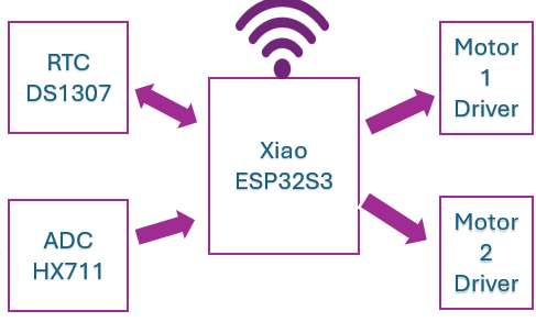
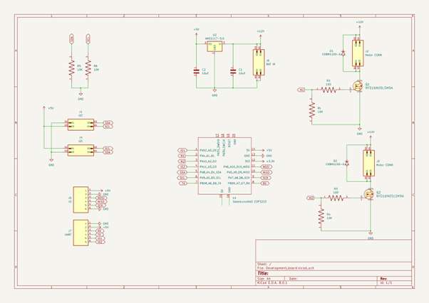
For this week's assignment, I intend to work on my final project board. The board will serve as a development board for use in the subsequent class and will also serve as a control board for my final project. It consists of xiao esp32 module couple with two mosfets that serves as motors driver and connectors for I2C, UART and IO pins.
I am used to Altium designer and Eagle CAD but for this course I want to try KiCAD because of it being open.
To Add seed xiao library I followed this tutorial OPL Kicad Library. For other components like the mosfet and connectors i used SnapEDA
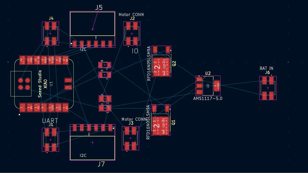
Component placement
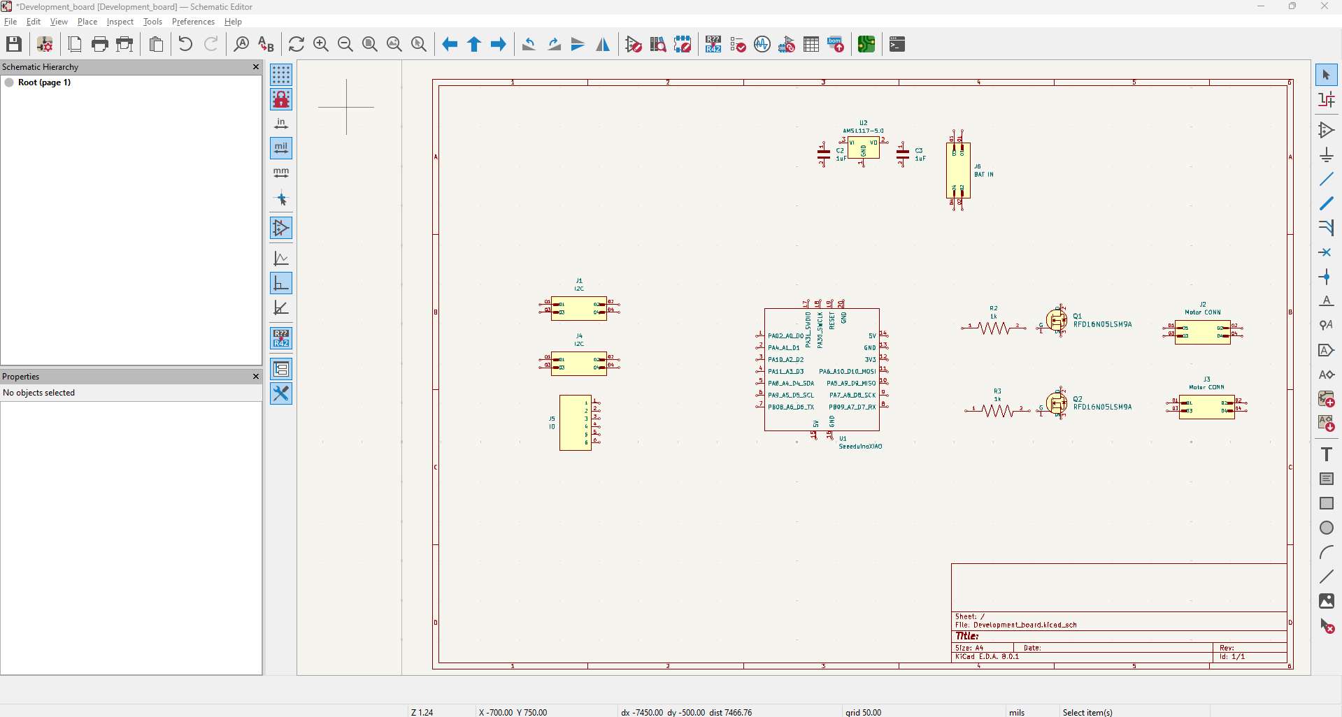
Wiring
Layout
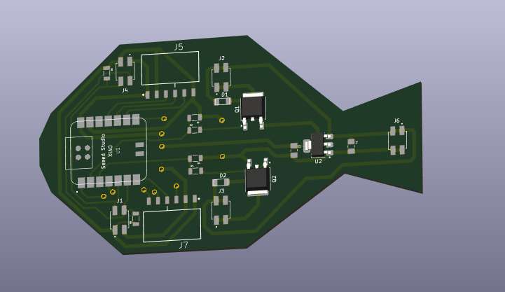
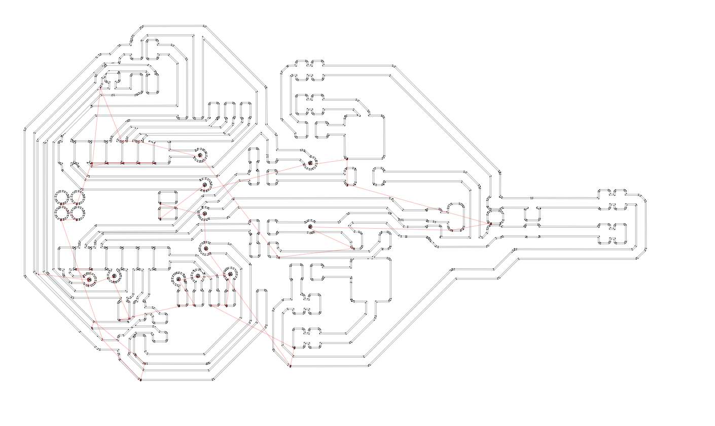
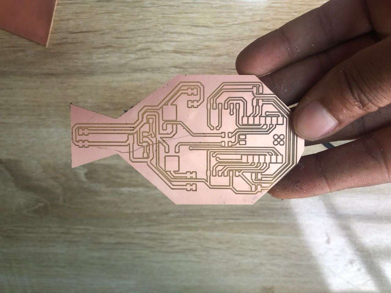
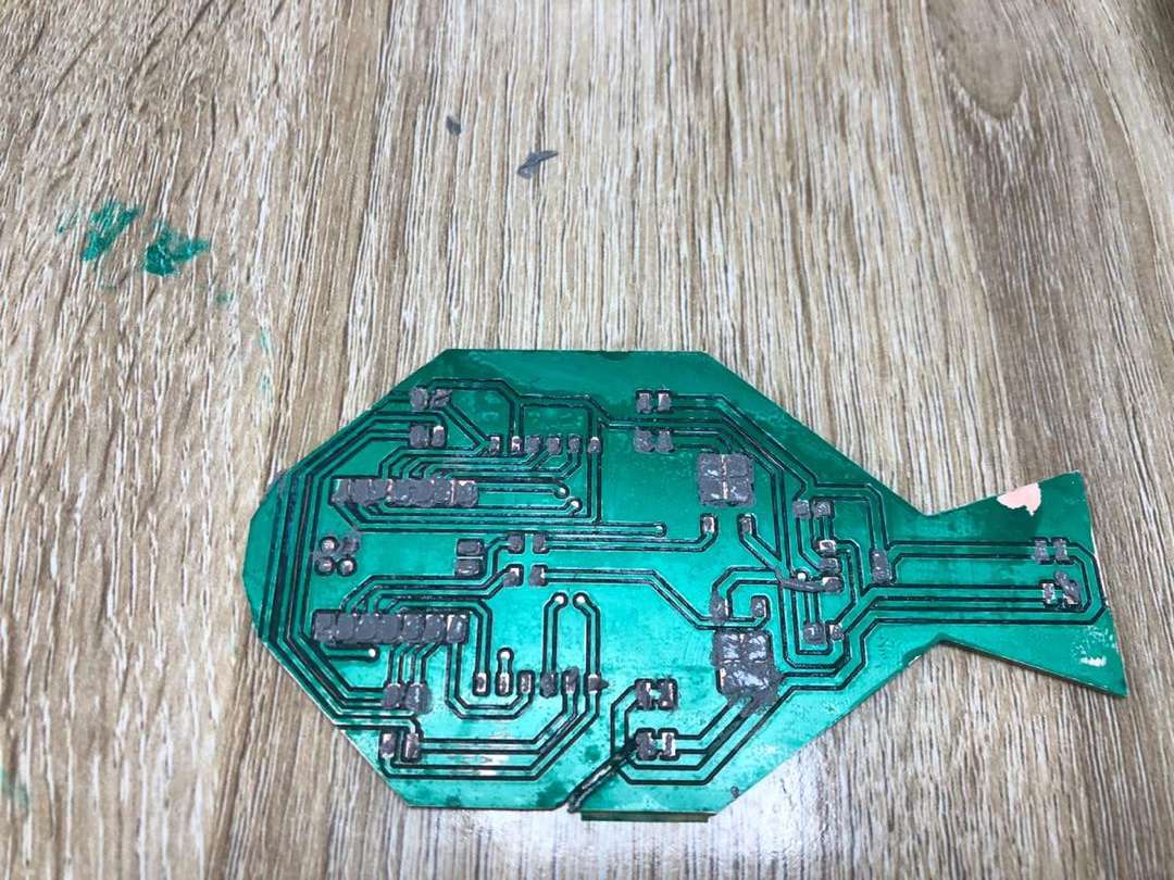
Since my project is about feeding fish, i placed the component and the board edge to form a fish shape
Routing
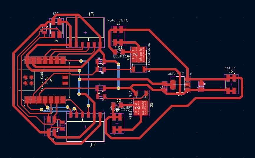
Board edge
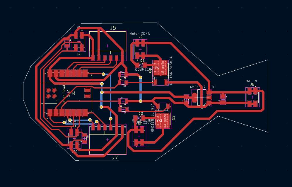
Final design
I used modsproject to generate toolpath for milling and board edge cutting
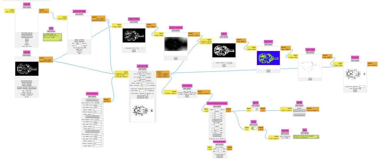
Output

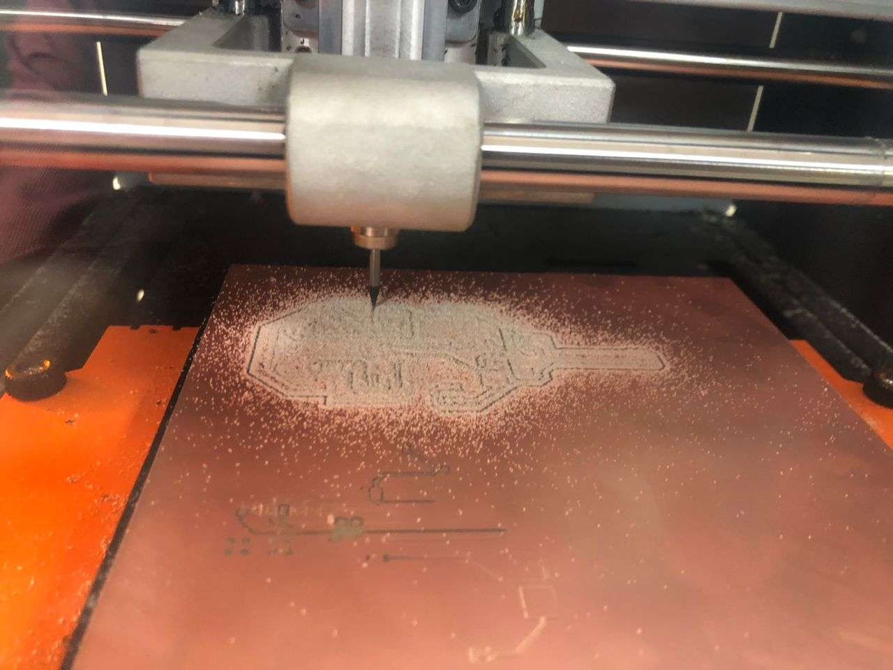
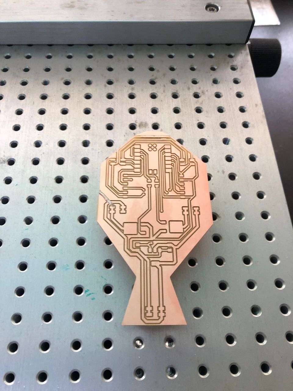
Milling traces
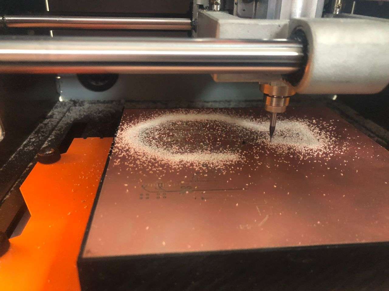
Cutting board edge
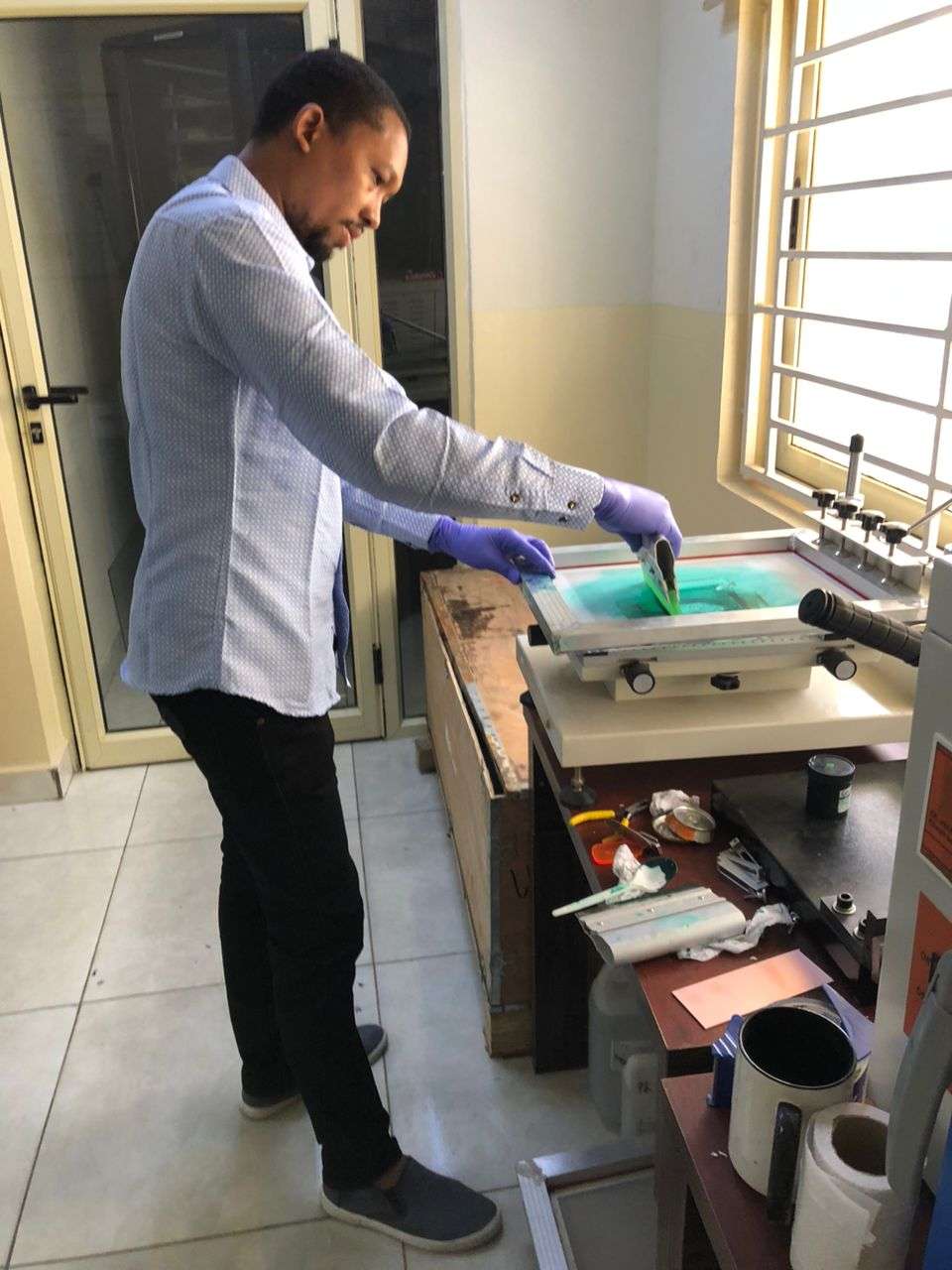
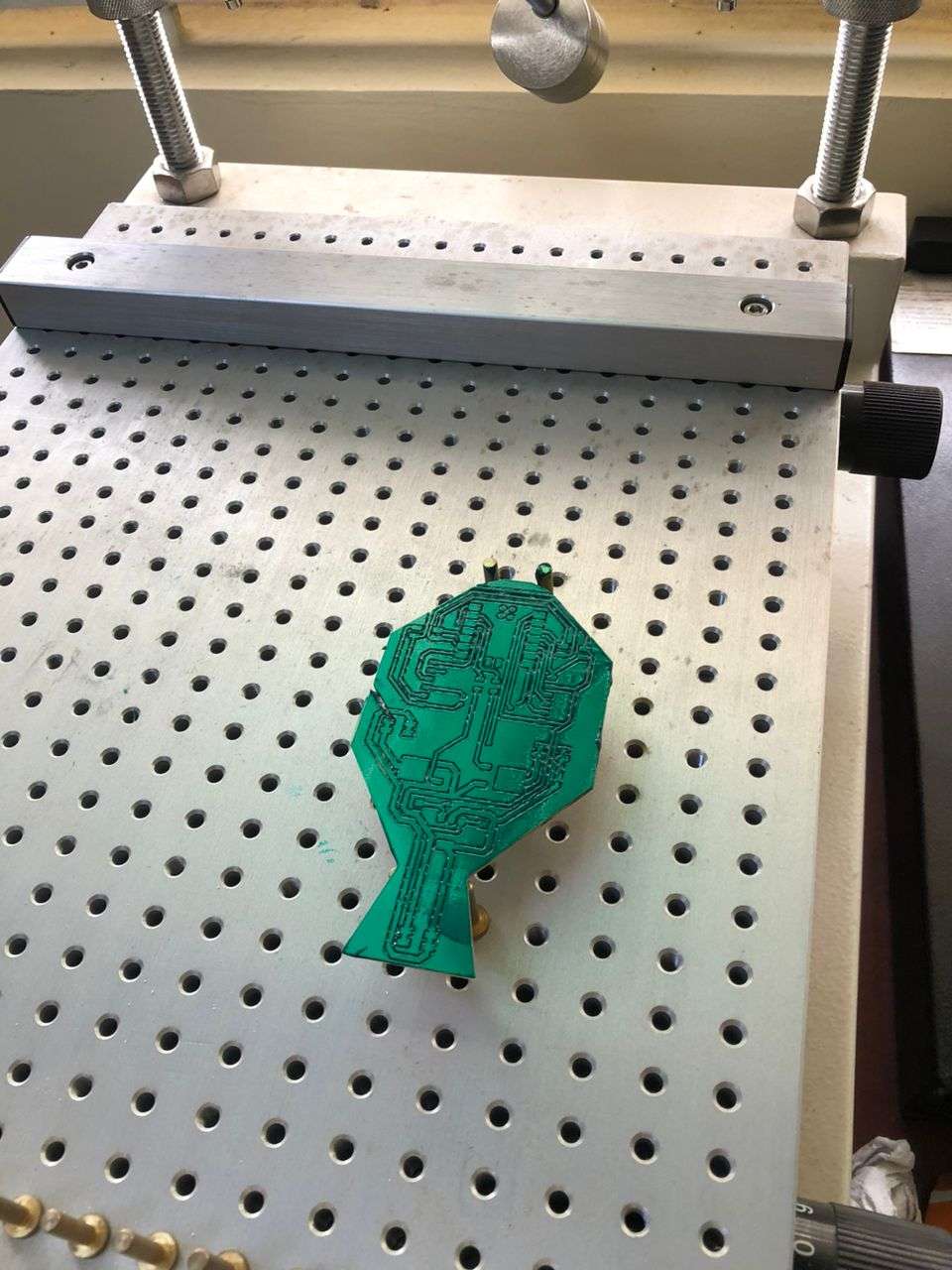
UV exposture

Result

I used soda can to produce stencil

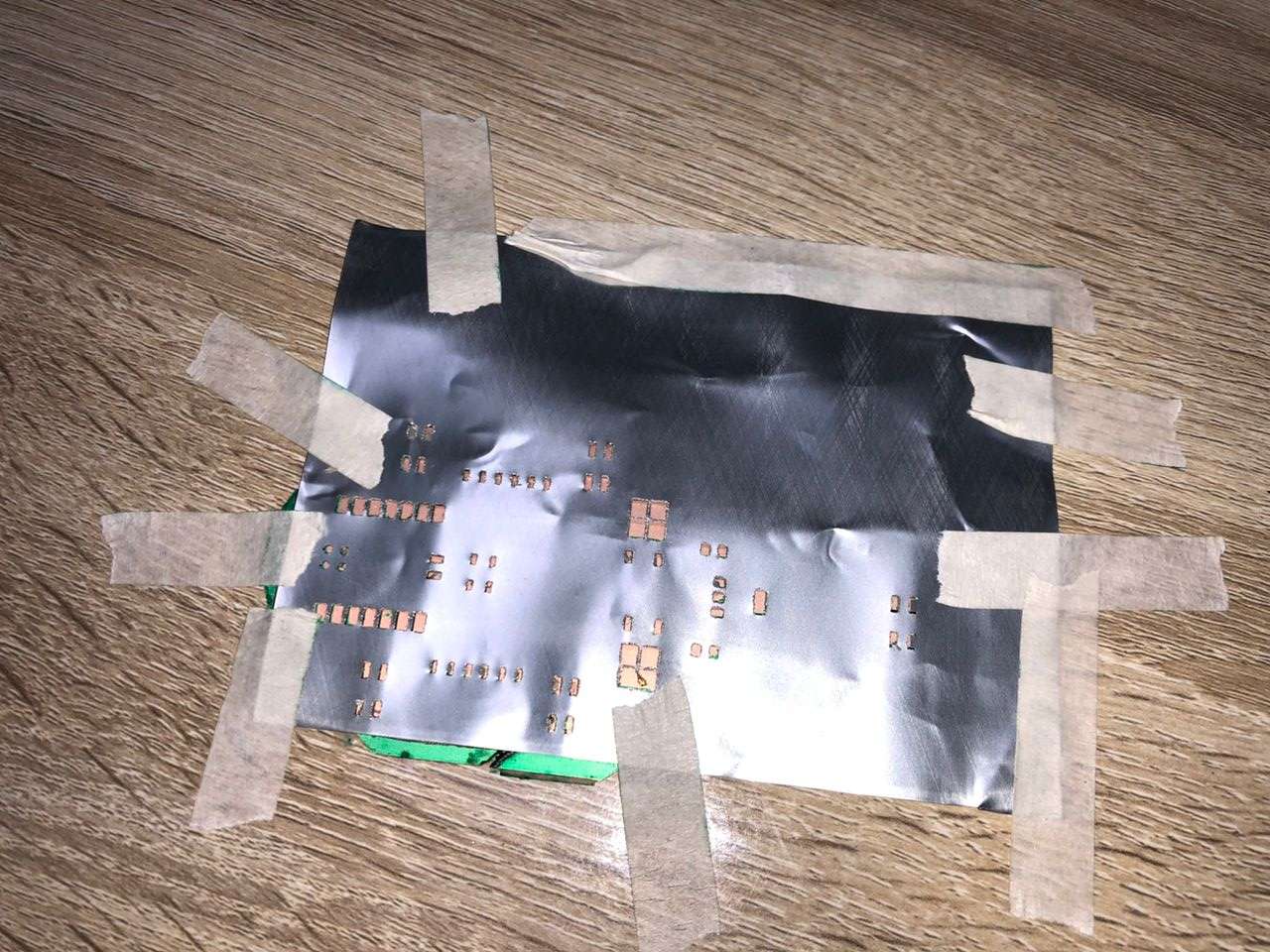
component placement

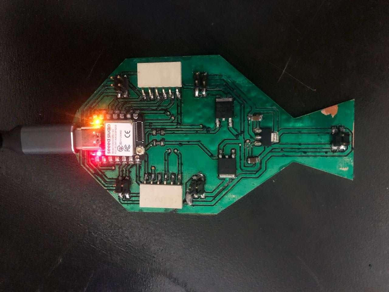
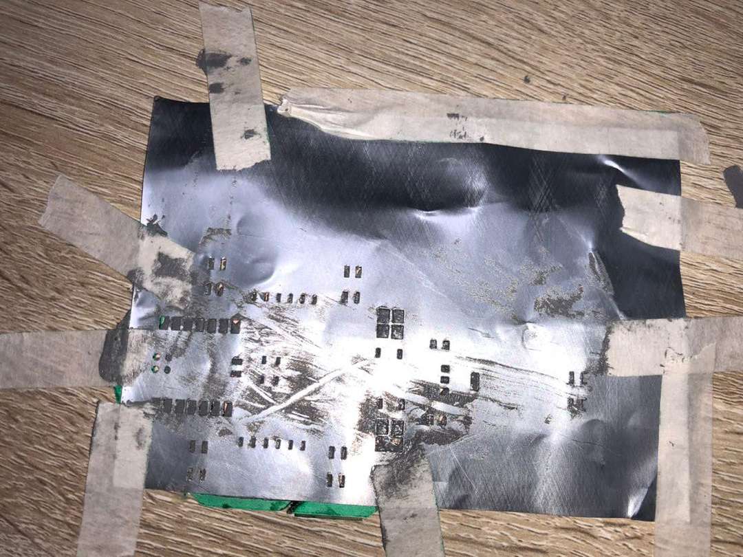
After placing the component I put the board in a reflow oven. But the outcome is not good. The oven blew away some of the components.
So I had to solder the remaining component manually

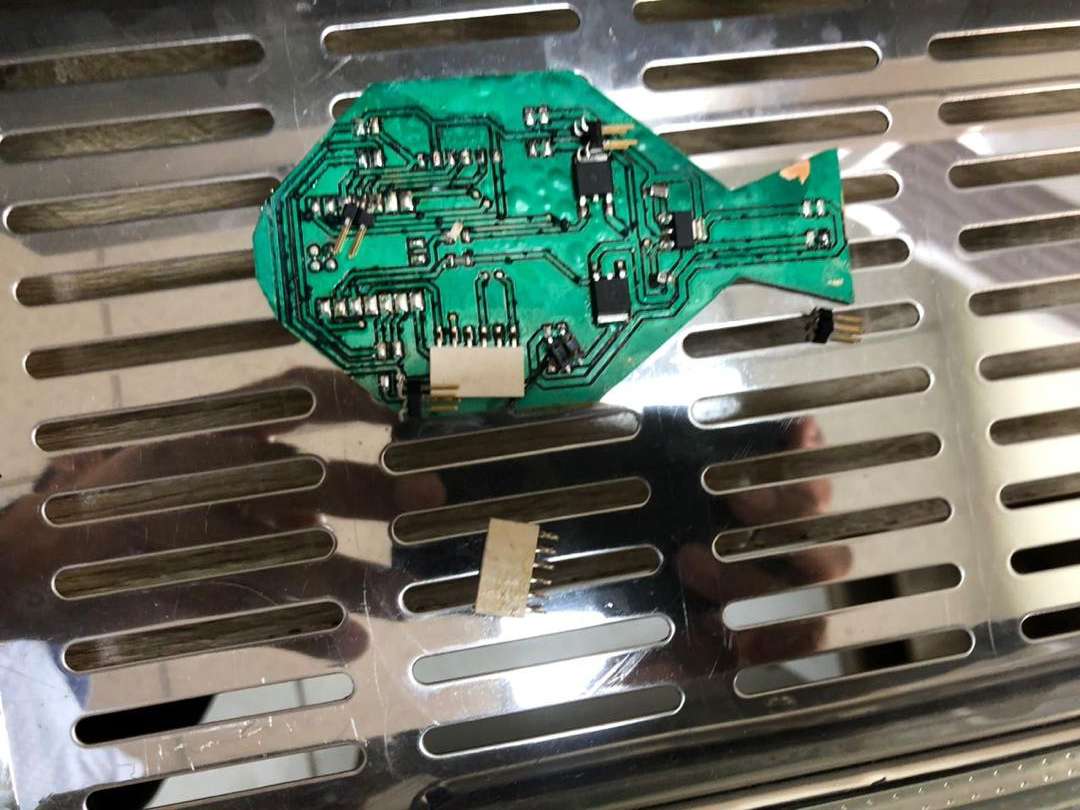
Result after soldering all the jumper wires
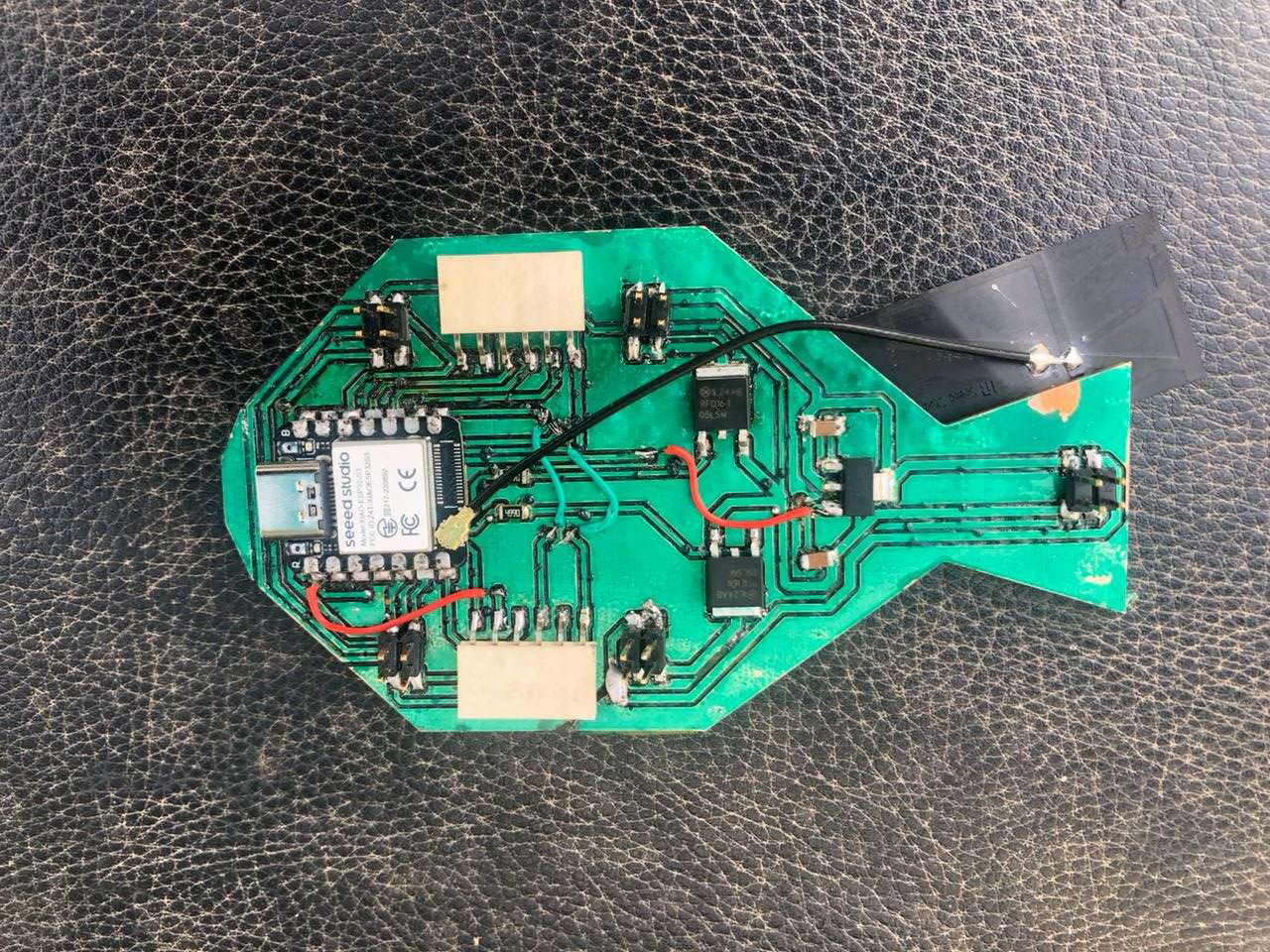
I did a continuity test of the power and signal lines. I also performed a power test by powering the xiao and testing for the voltage levels at the connectors.