This week's activities revolved around machines, materials, vendors, tooling, fixturing, and safety protocols pertinent to fabrication processes. We explored a variety of machines such as Shaper, Maslow, ShopBot, and Tormach, along with stock materials like cardboard, plywood, HDPE, and aluminum sourced from vendors like McMaster-Carr and US Plastics. Job shops such as Proto Labs and Star Rapid were examined for outsourcing needs, while tooling considerations encompassed drills, mills, router bits, coatings, and lubricants.
Understanding speeds and feeds, lubrication techniques, and abrasive machining methods was essential for efficient material removal. Fixturing strategies involving vises, clamps, vacuum systems, and adhesives were explored to secure workpieces during machining operations. We delved into jointing techniques, fasteners, glues, and sacrificial layers to facilitate fabrication processes effectively.
Additionally, comprehensive discussions on toolpaths, CAM software like VCarvePro and Fusion 360, and safety measures including personal protective equipment (PPE), training, and emergency protocols were covered to ensure a safe and productive working environment. Welding techniques including arc, MIG, TIG, and spot welding were also examined, enhancing our understanding of fabrication processes and capabilities.
This week's assignment is about understanding how to use big CNC machines in the lab
For details on this assignment head to our Group assignment page
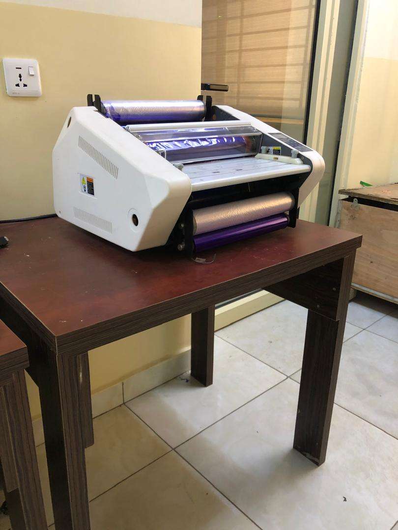
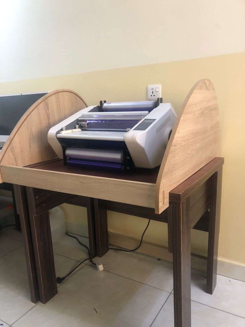
In our lab (Abuja Fablab 1.0) we have a PCB production facility that is used for making small and medium quantities of boards using chemical processes. One of these processes involved film lamination using this machine bellow:
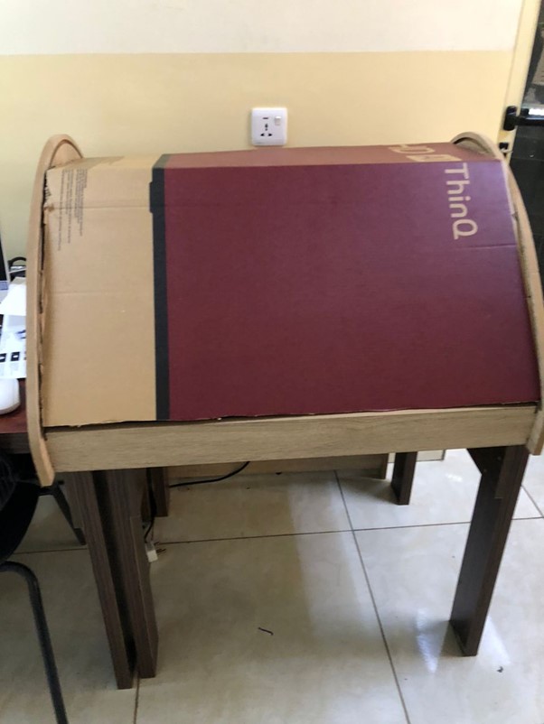
We are having problems with films being exposed to direct sunlight through the window and the room lighting. Eventually it expires before it could be fully utilized.
I want to use this week's assignment to create a cover for the machine when it is not being used. I intend to make the cover fit with the existing table where the machine is sitting on.
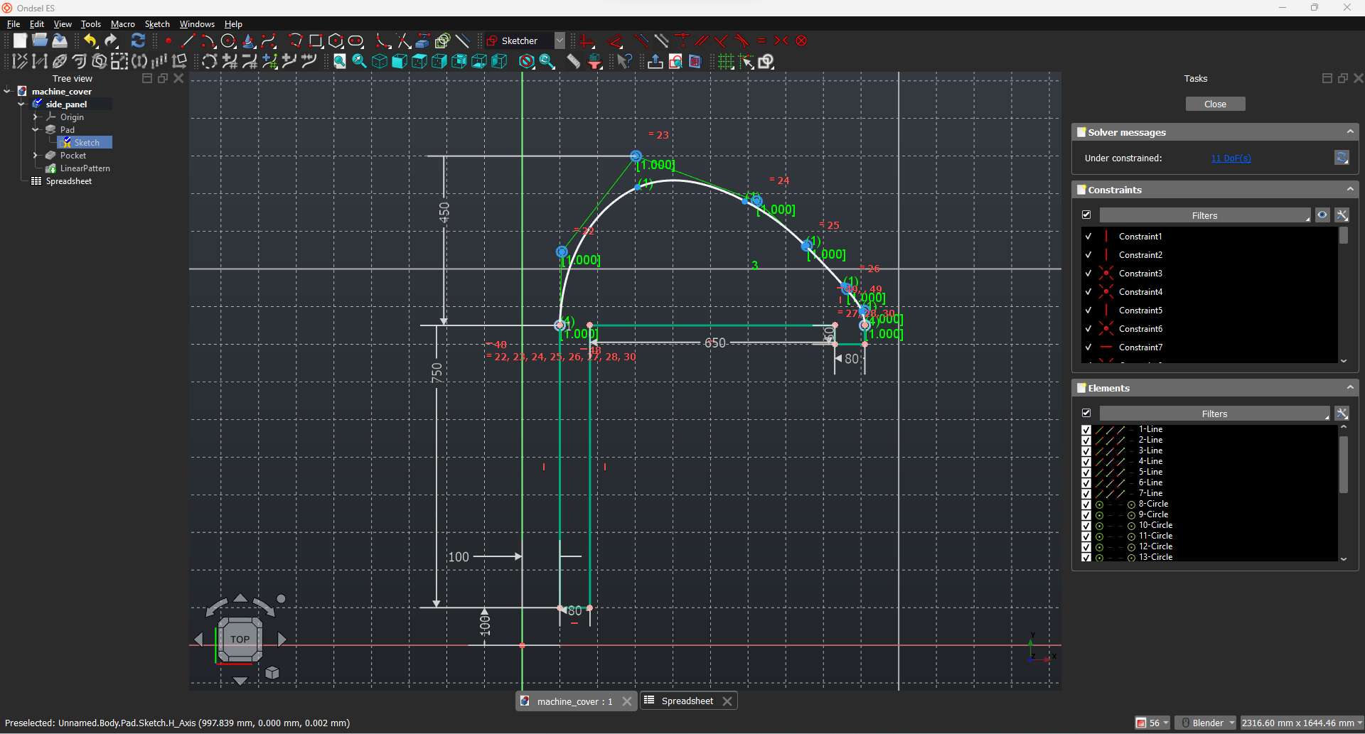
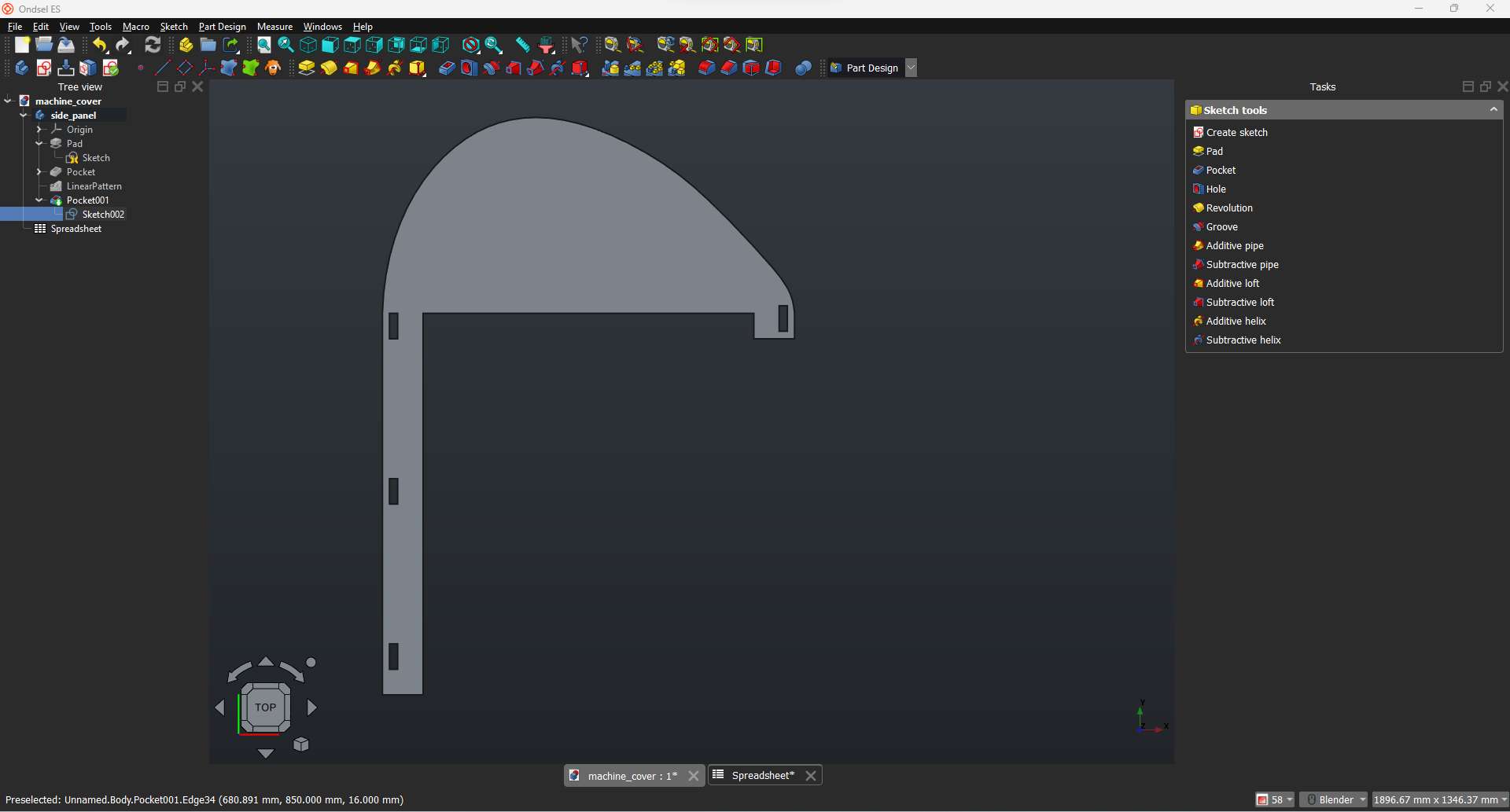
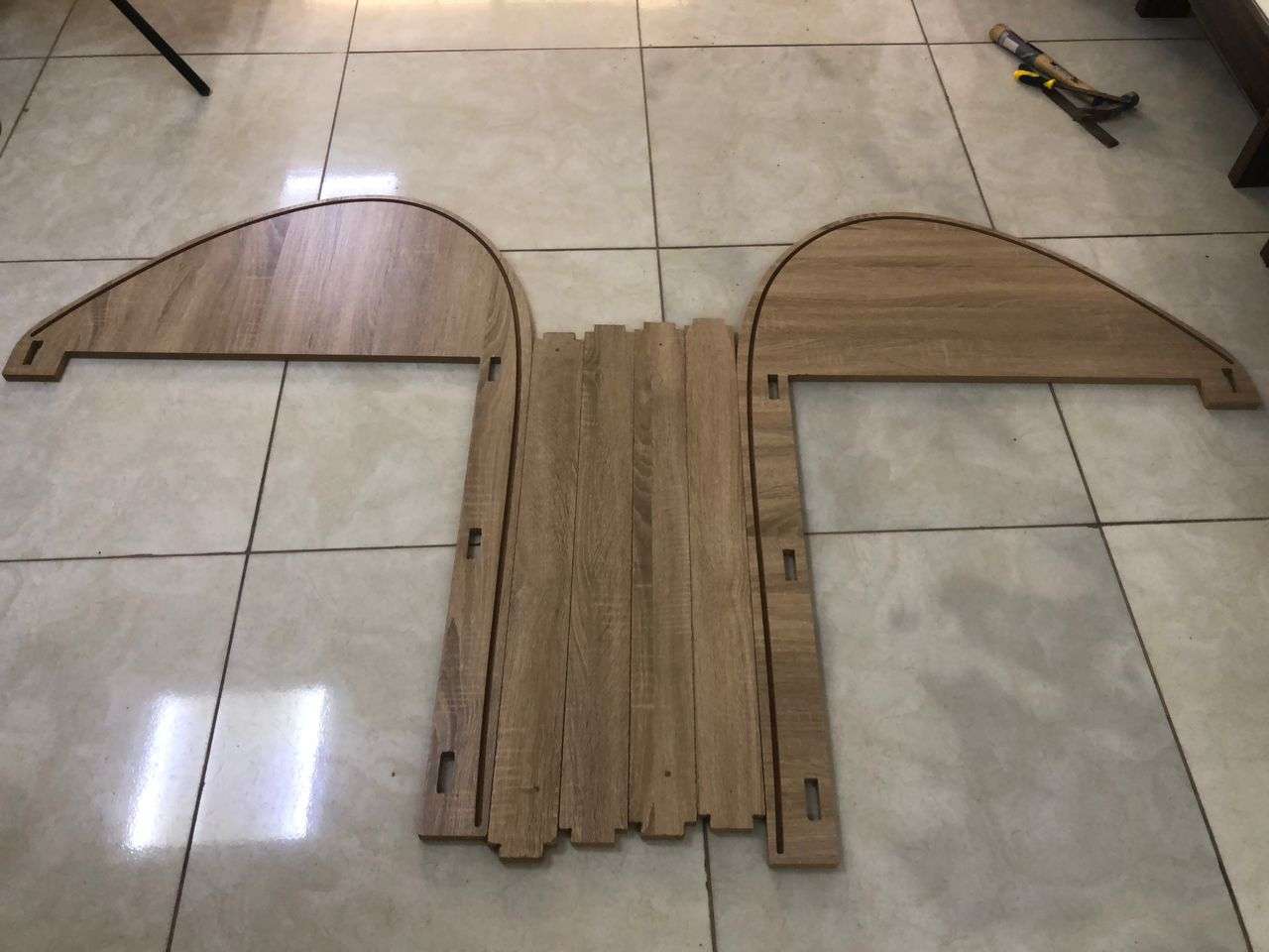
After getting the measurement of the existing based table of the machine, I used ondSel ES (FreeCAD) CAD tool to design two panels (side panel and connection panels).
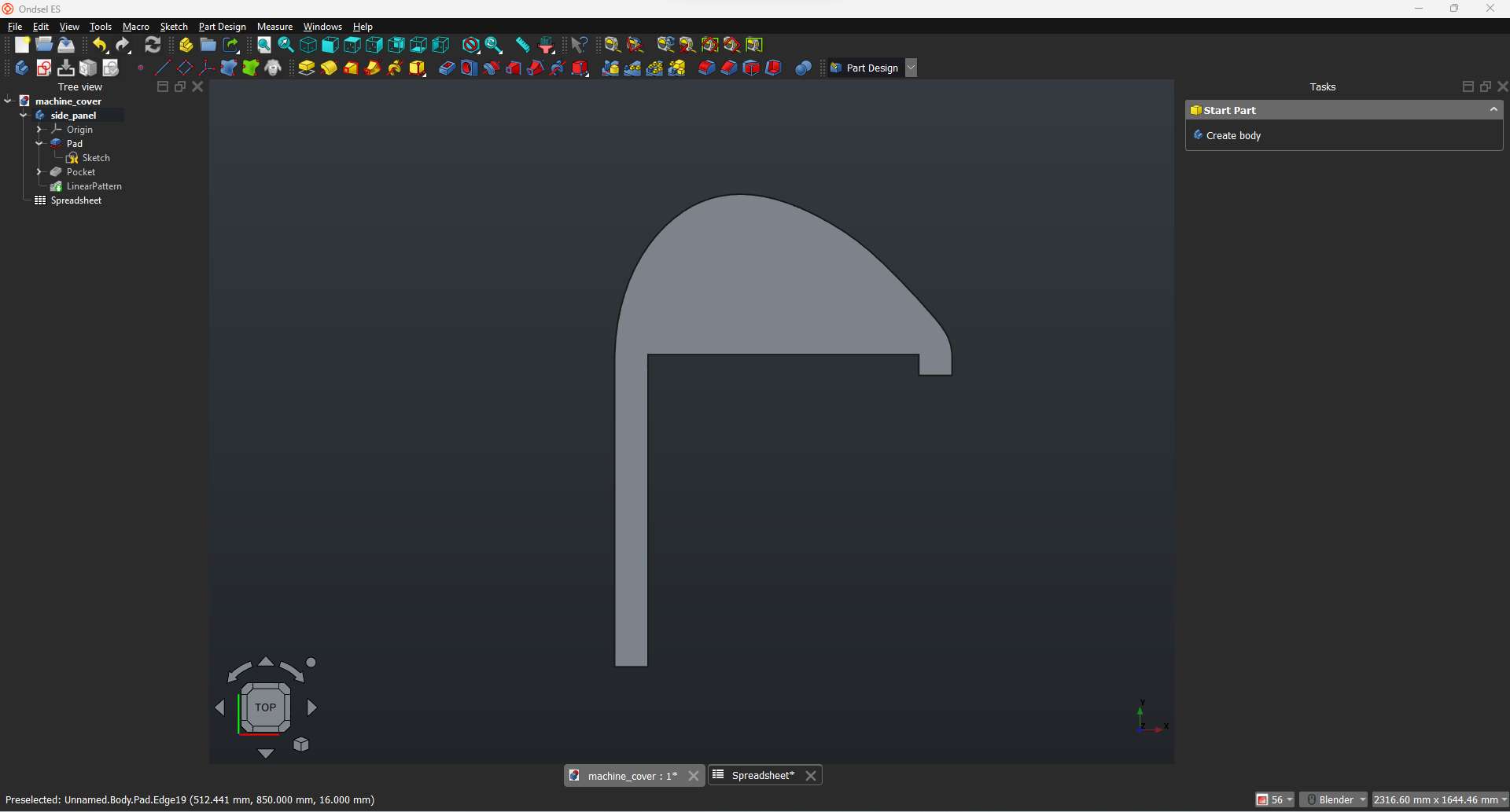
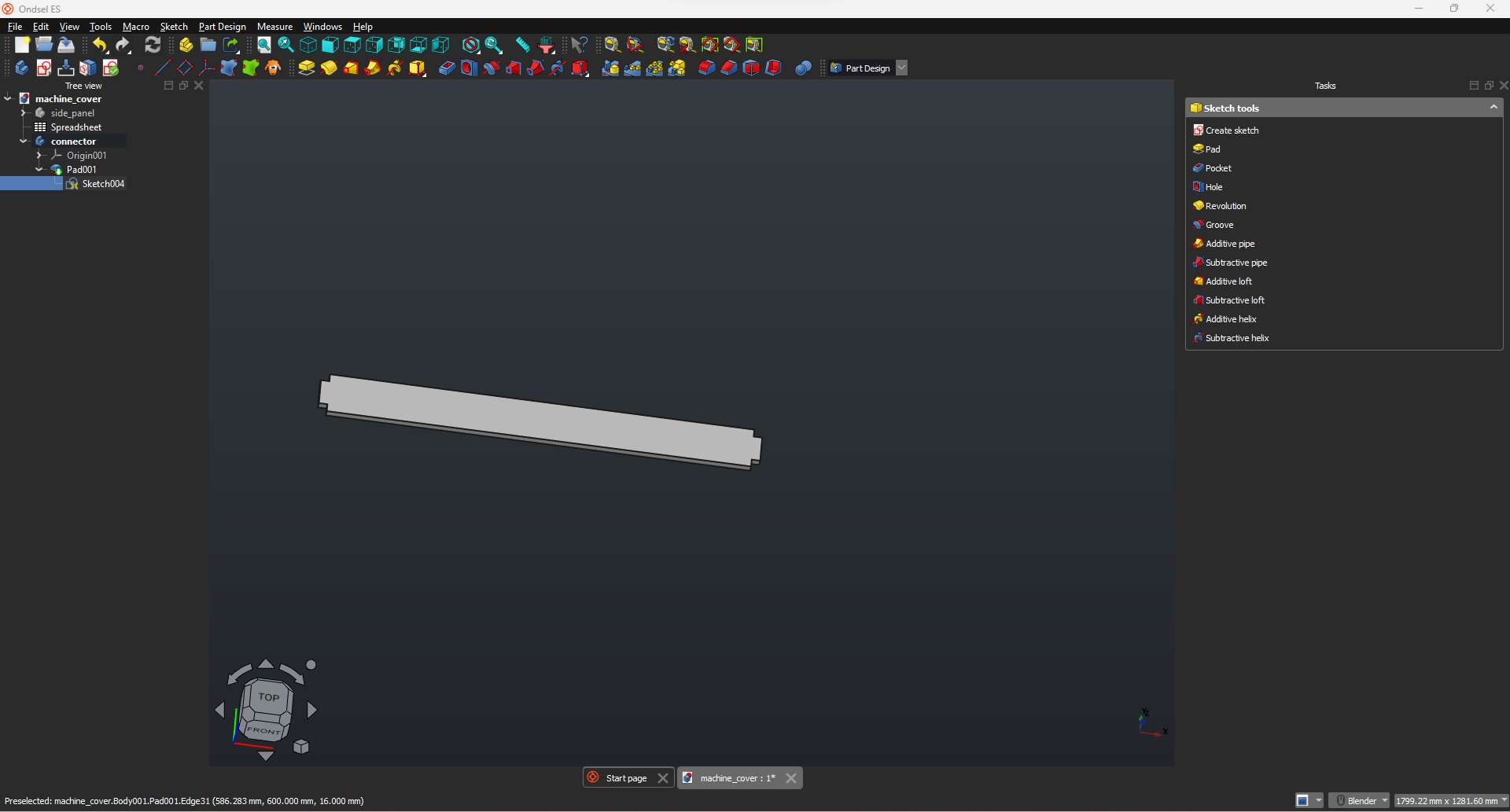
I sketched this panel using plyline and B-spline tools then I padded it to the thickness of my stock (16mm). I needed two of this panel to serve as the side cover as well as the main structure to hold the top sliding cover. I also created grooves that acts as a joining point for the connecting panels.
Sketch
Pad
Groove for joining the connecting panels
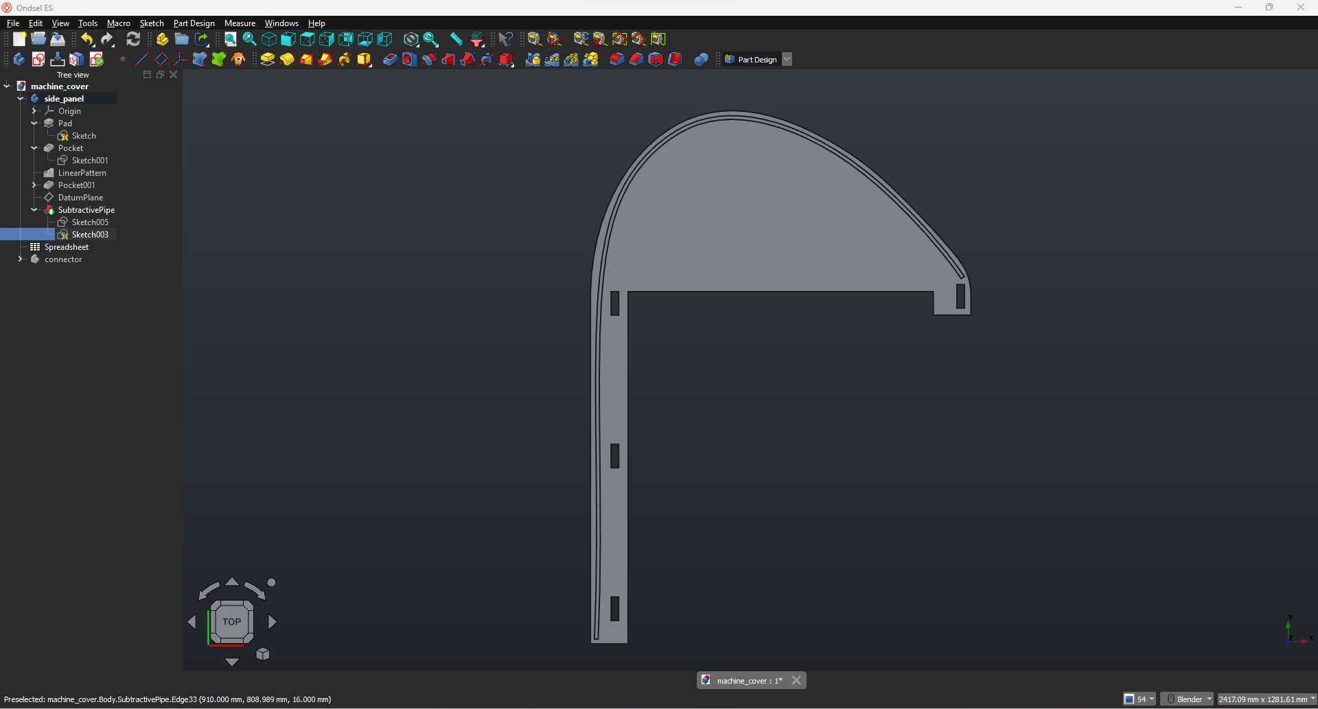
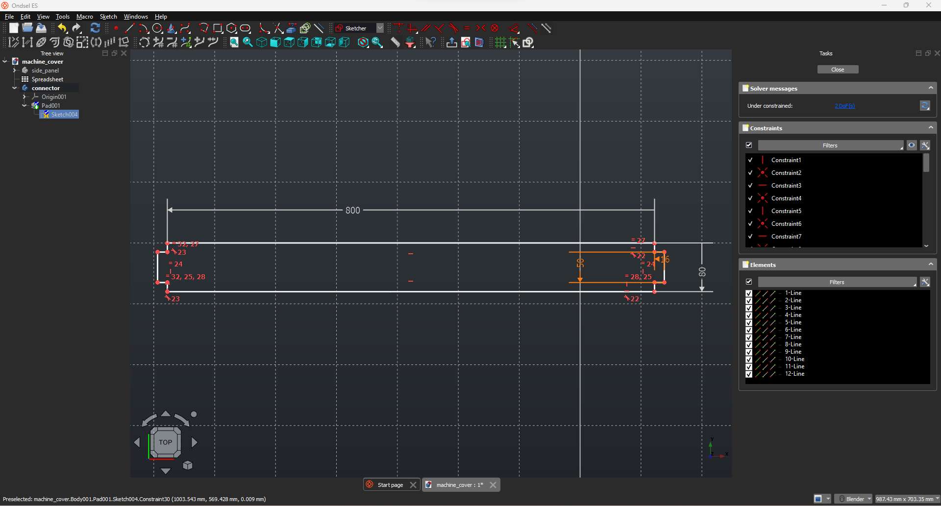
The top sliding cover needs to be sliding in a curvature groove so I added a B-spline on the side panel.
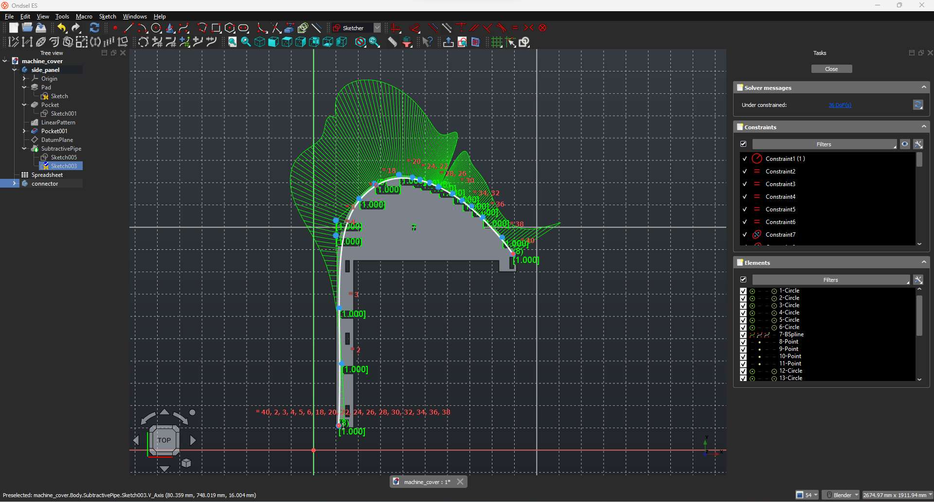
To get the groove etched on the panel, I sketched a rectangle at the tip of the B-spline and performed subtractive pipe action on the panel along the B-spline using the rectangle.
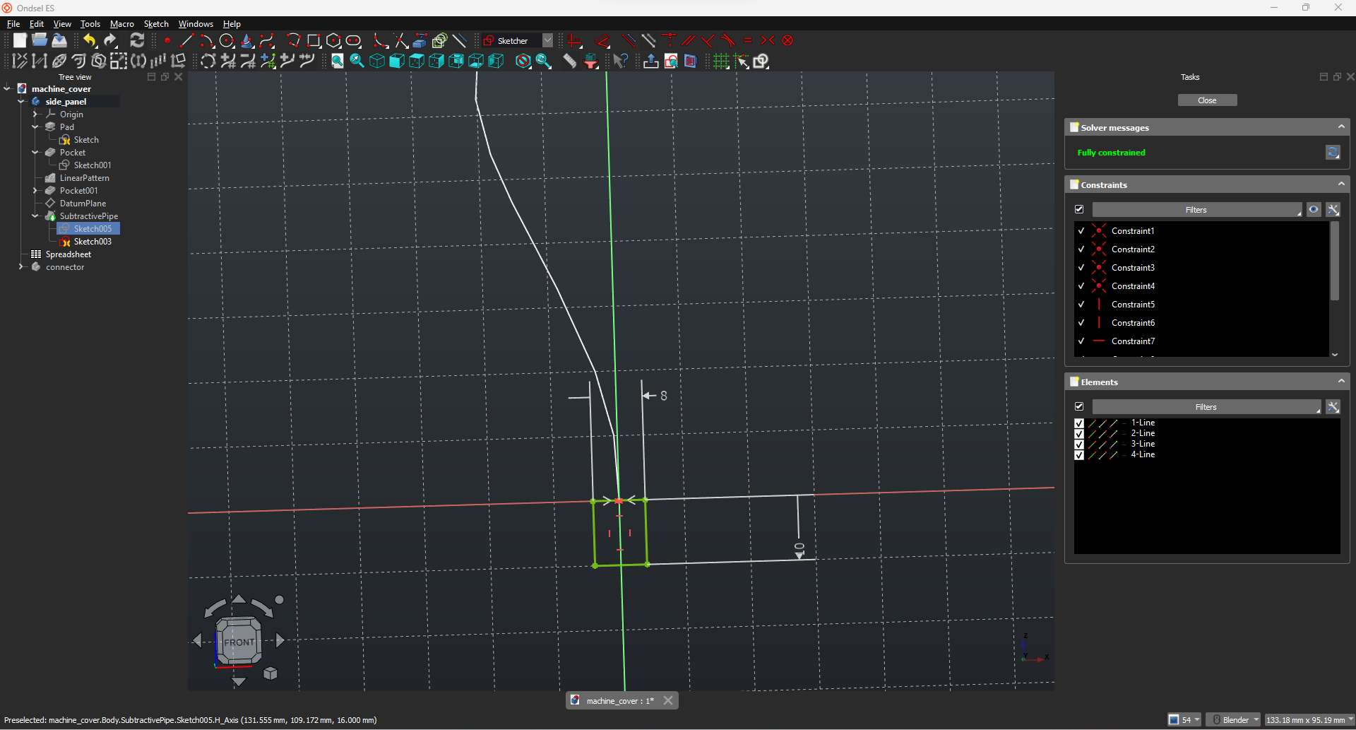
Subtractive pipe
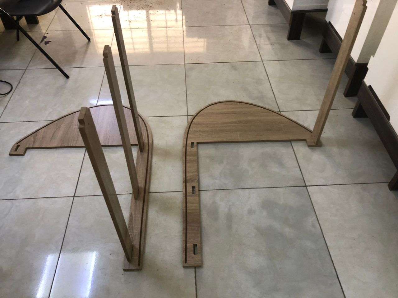
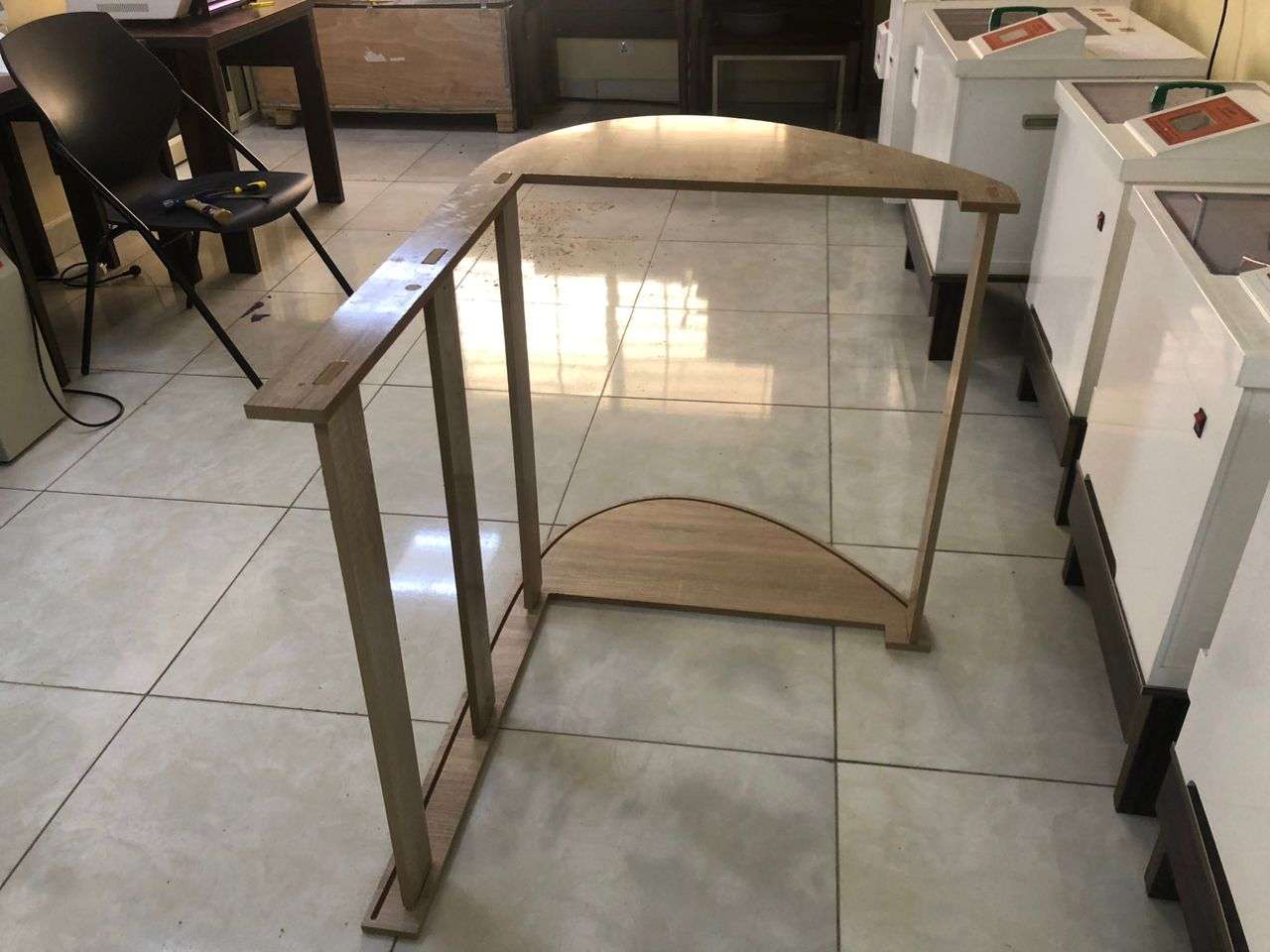
The connecting planes runs across the length of the existing table to connect the side panels
Sketch
Pad
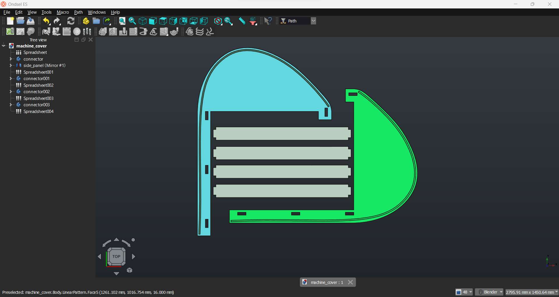
I have mirrored the side panel to get the other side panel and duplicated the connecting panels to get the required number (4) for supporting the structure.
OndSel ES has a toolpath workbench so I intend to use it and create the tool path for machining. Though I have never used it before and in our lab we only used Aspire to do the 2D design and create tool paths.
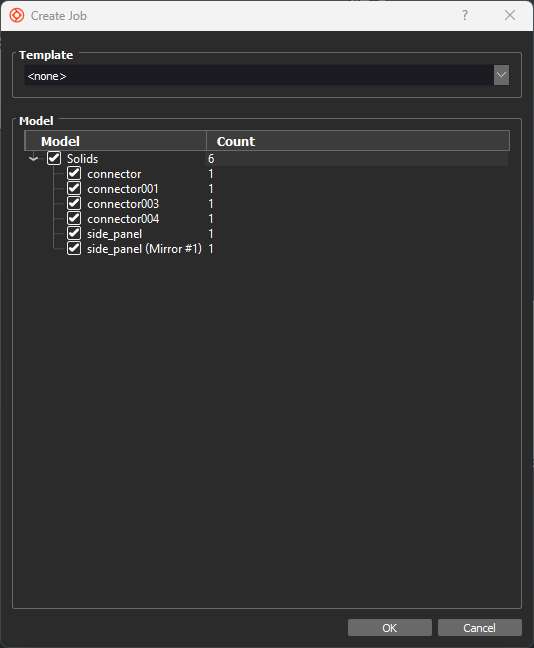
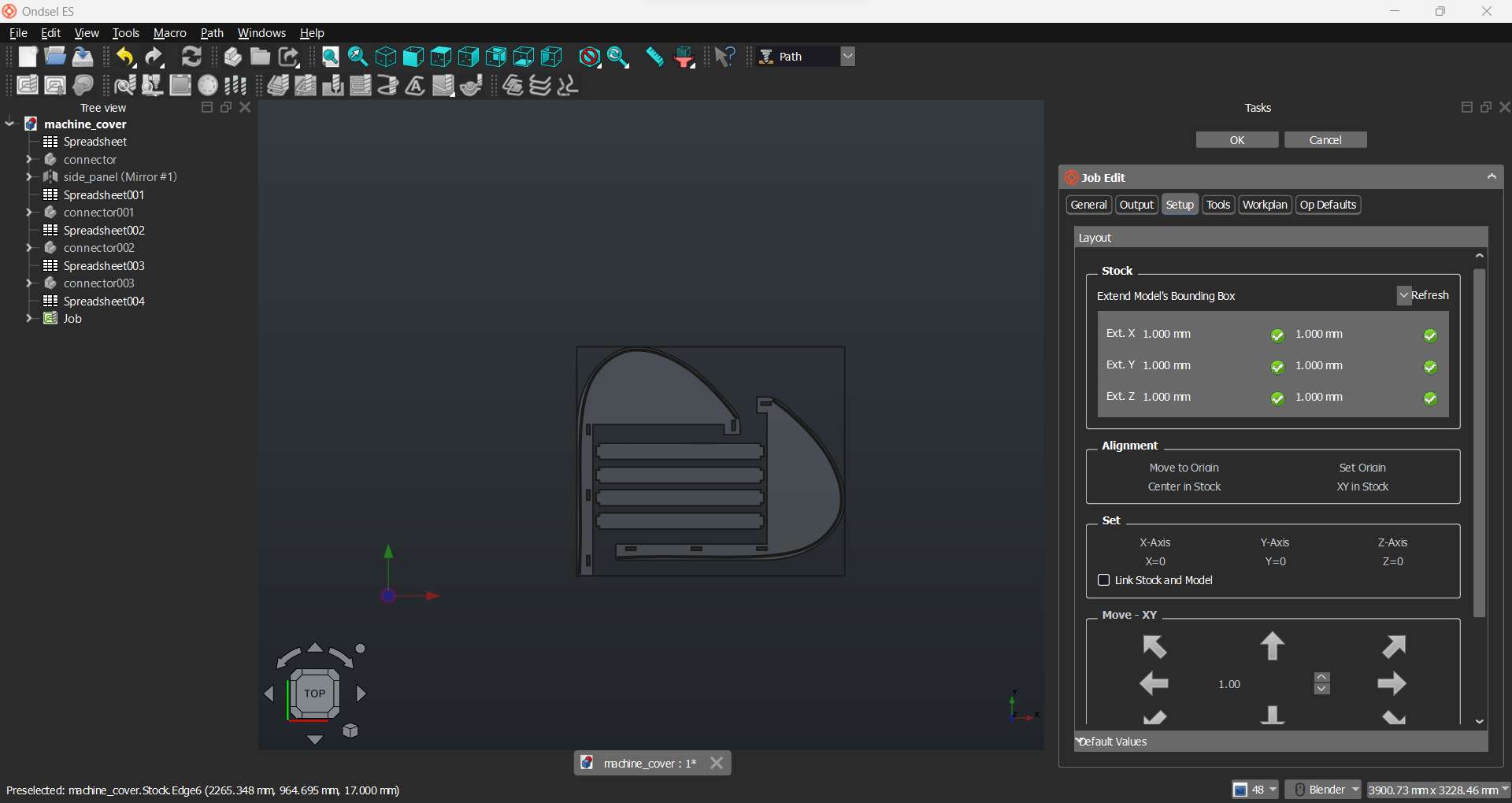
Switching to Path workbench I created a job and imported all my models
Here I set the stock properties from the job setting panel
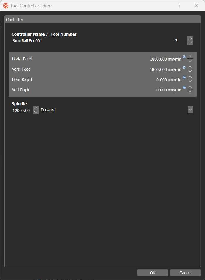
Then I selected the bit (size and type) and added the feed rate and spindle speed.
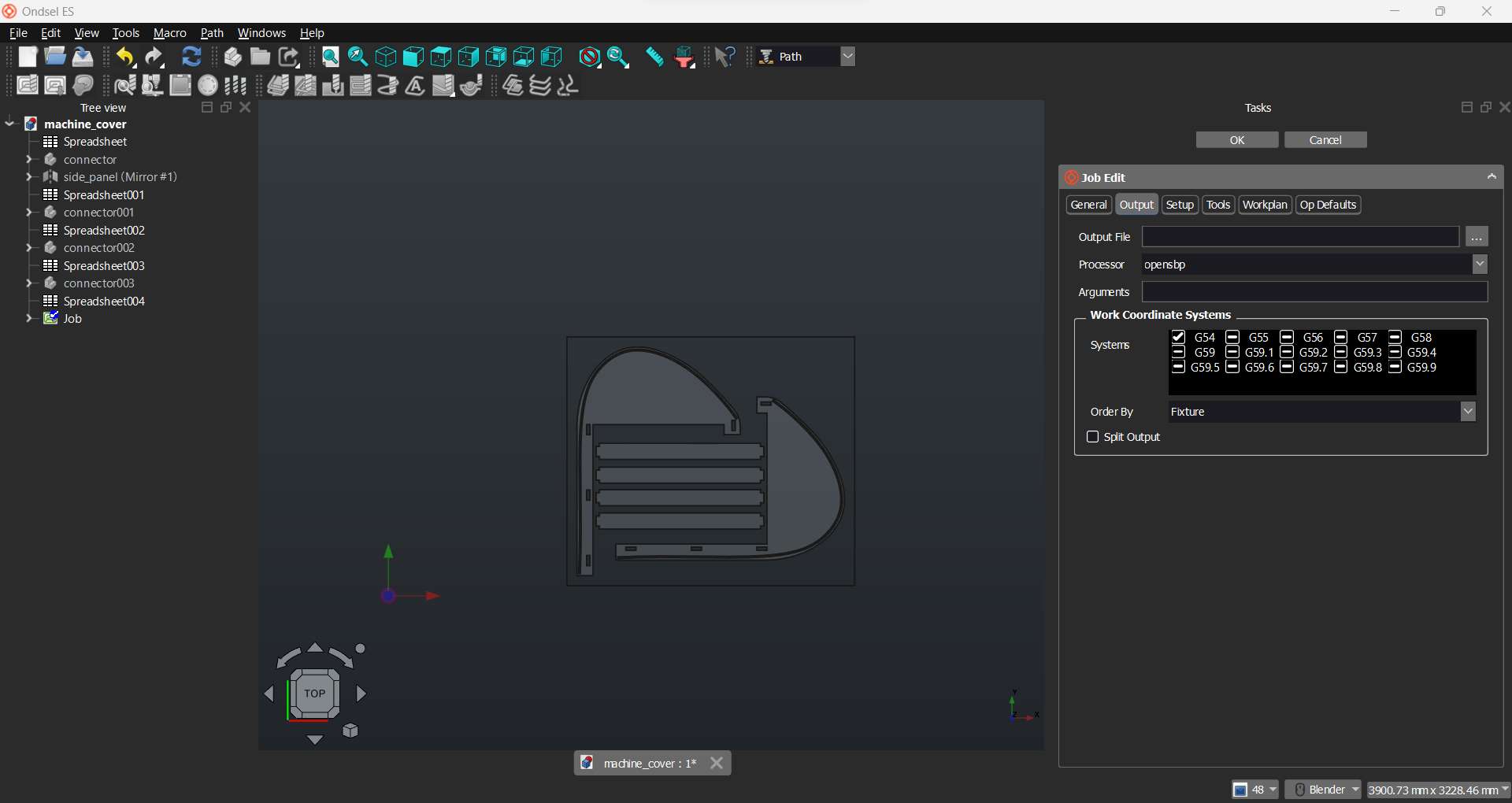
Now, I set the type of out file and properties of the file. I chose opensbp (open shopbot part extension) and G54 coordinate system.
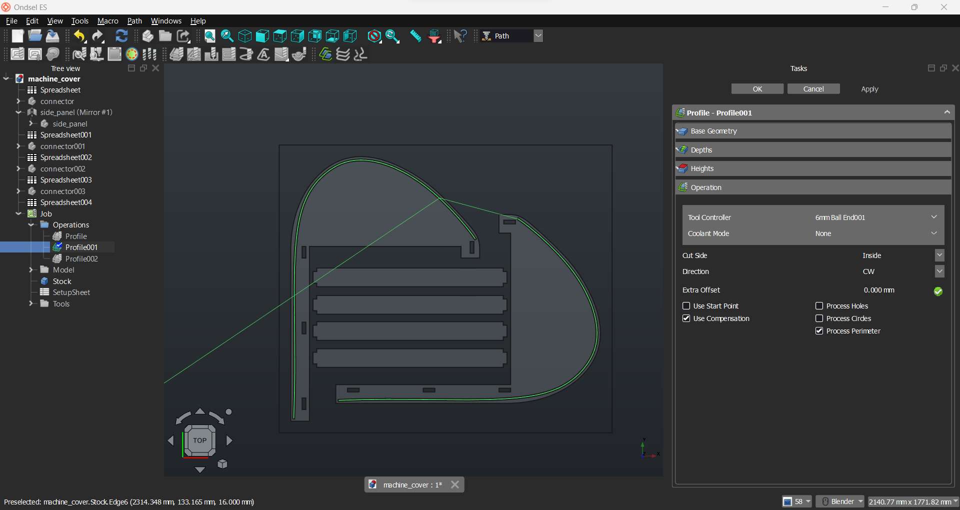
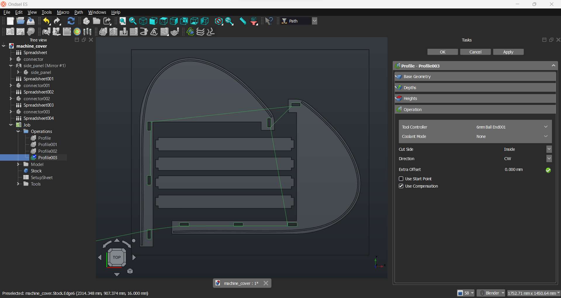
Here I created an operation to be performed on the stock using my imported models' edges.
Profile of side panels
Profile of connectors
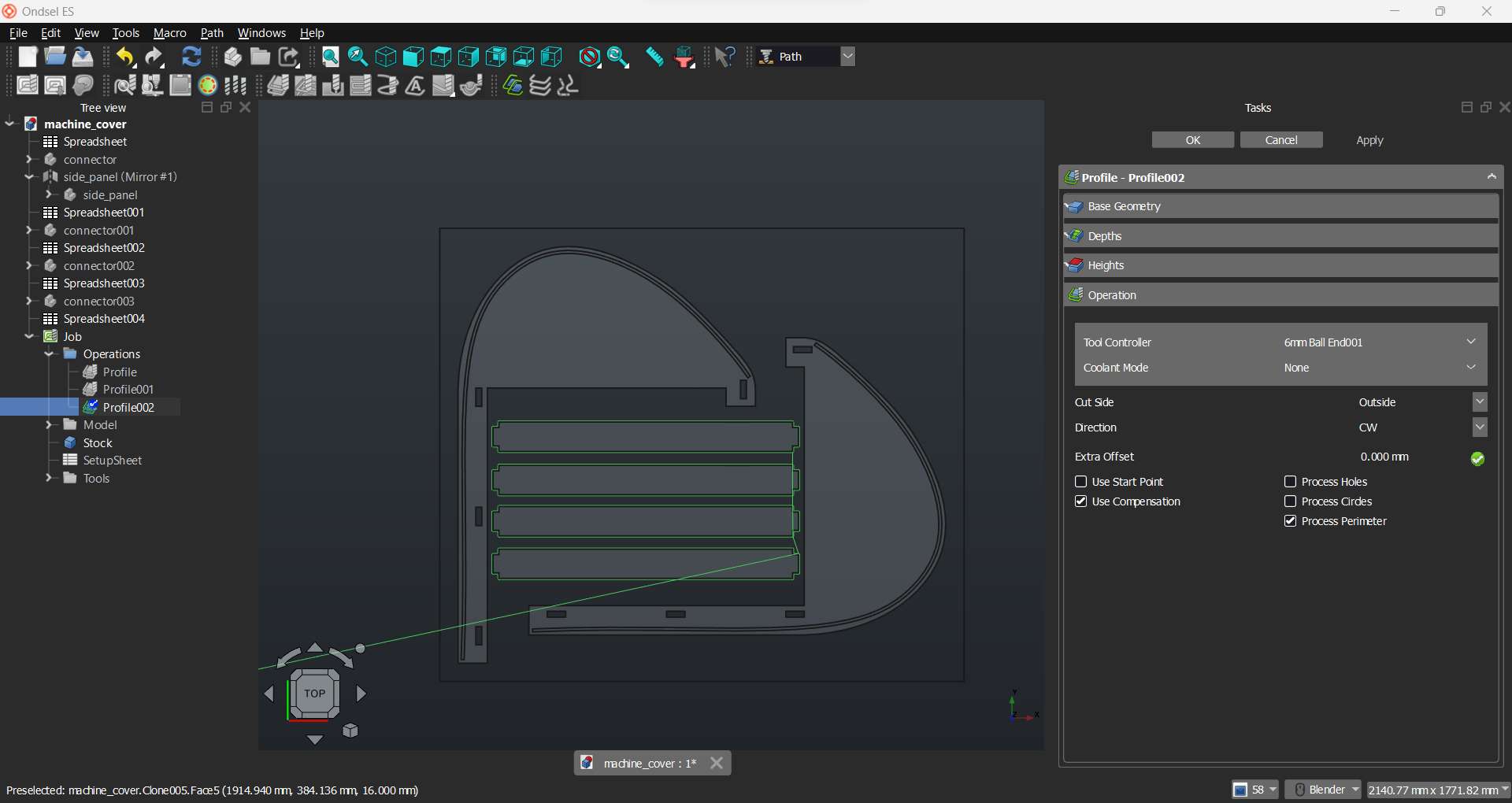
Profile of slider groove
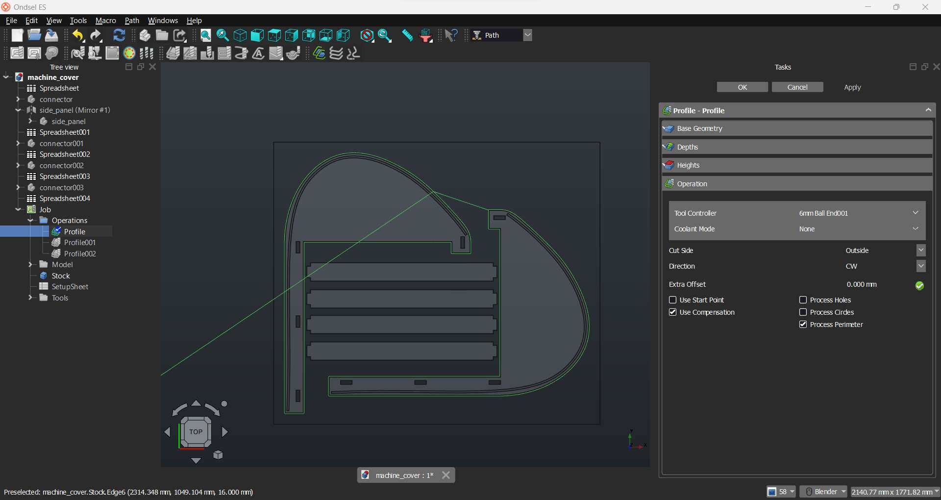
Profile of connector groove
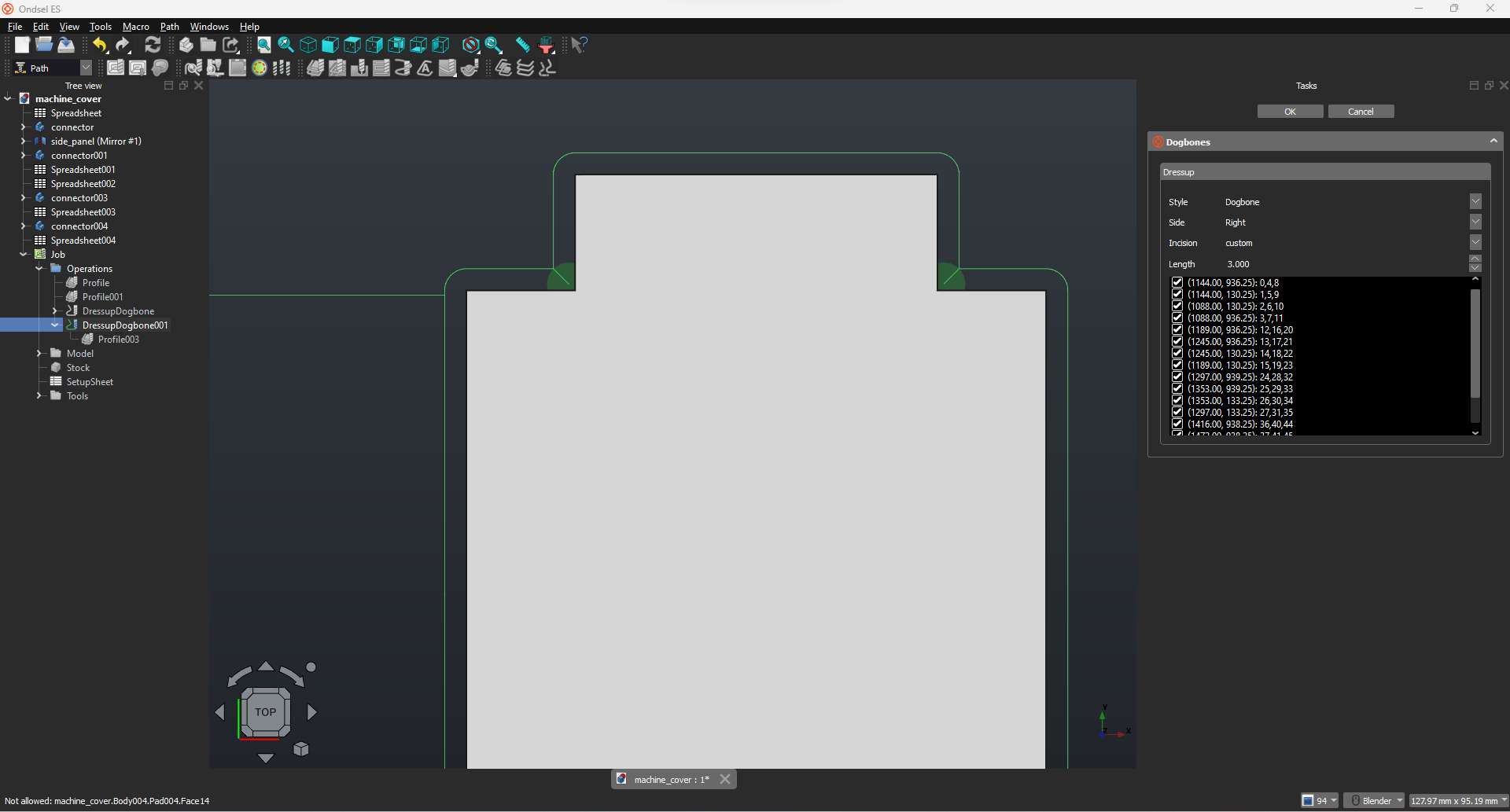
I have added dogbone dress up on the grooves profiles
Dogbone for grooves
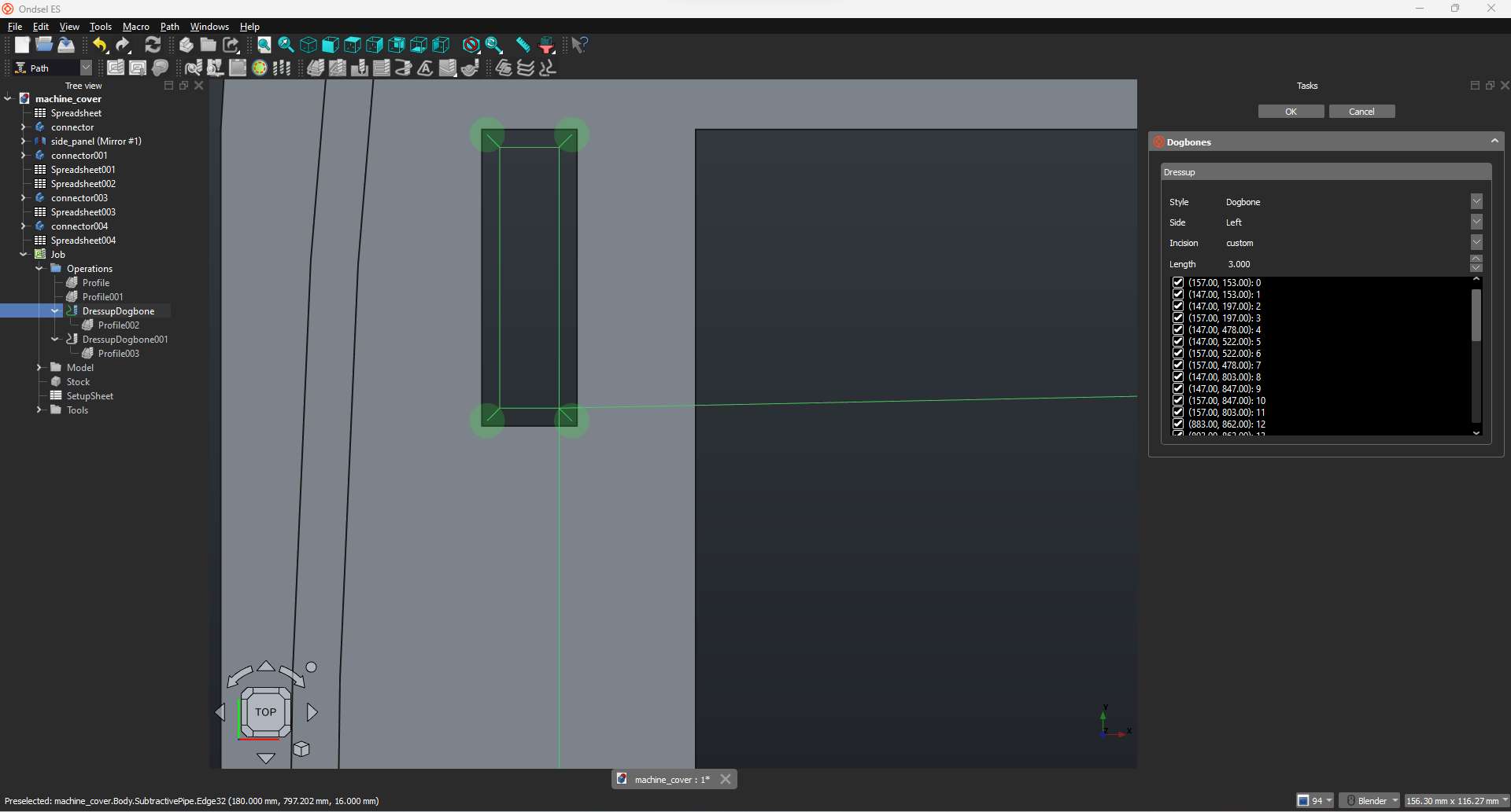
Dogbone for connectors
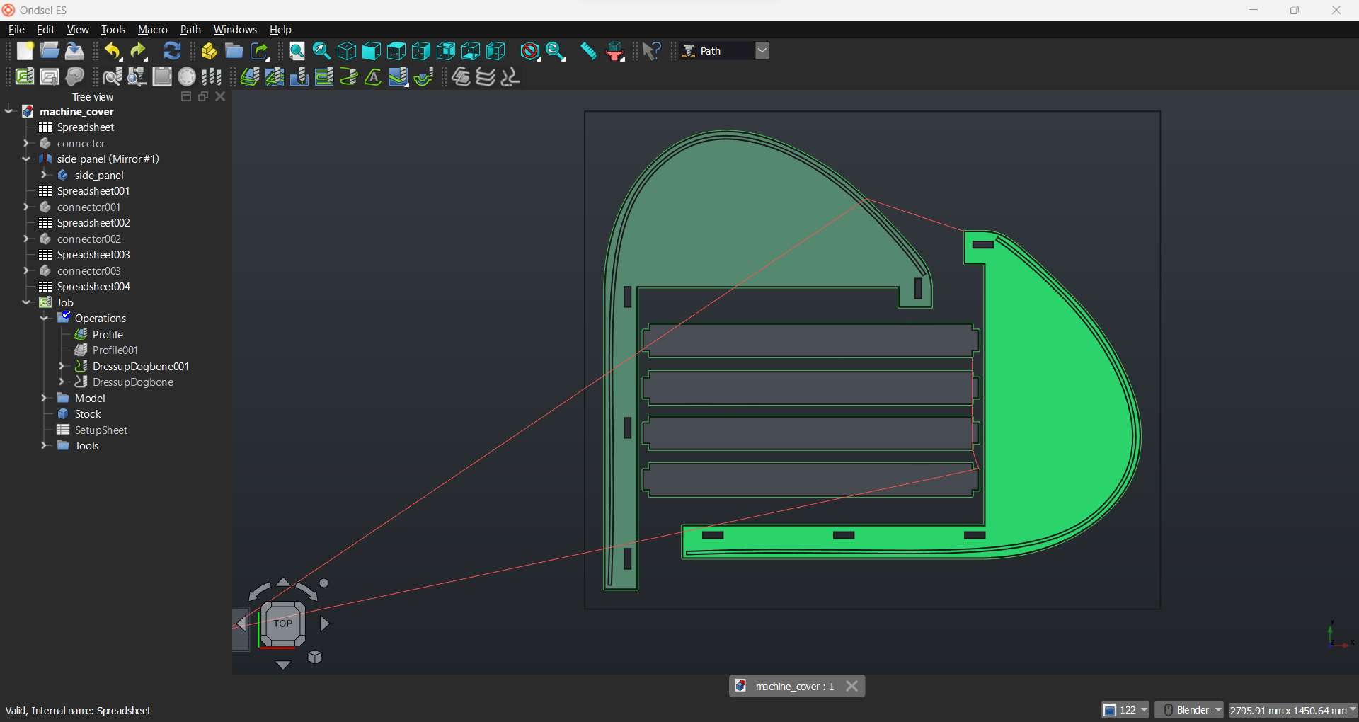
Complete paths
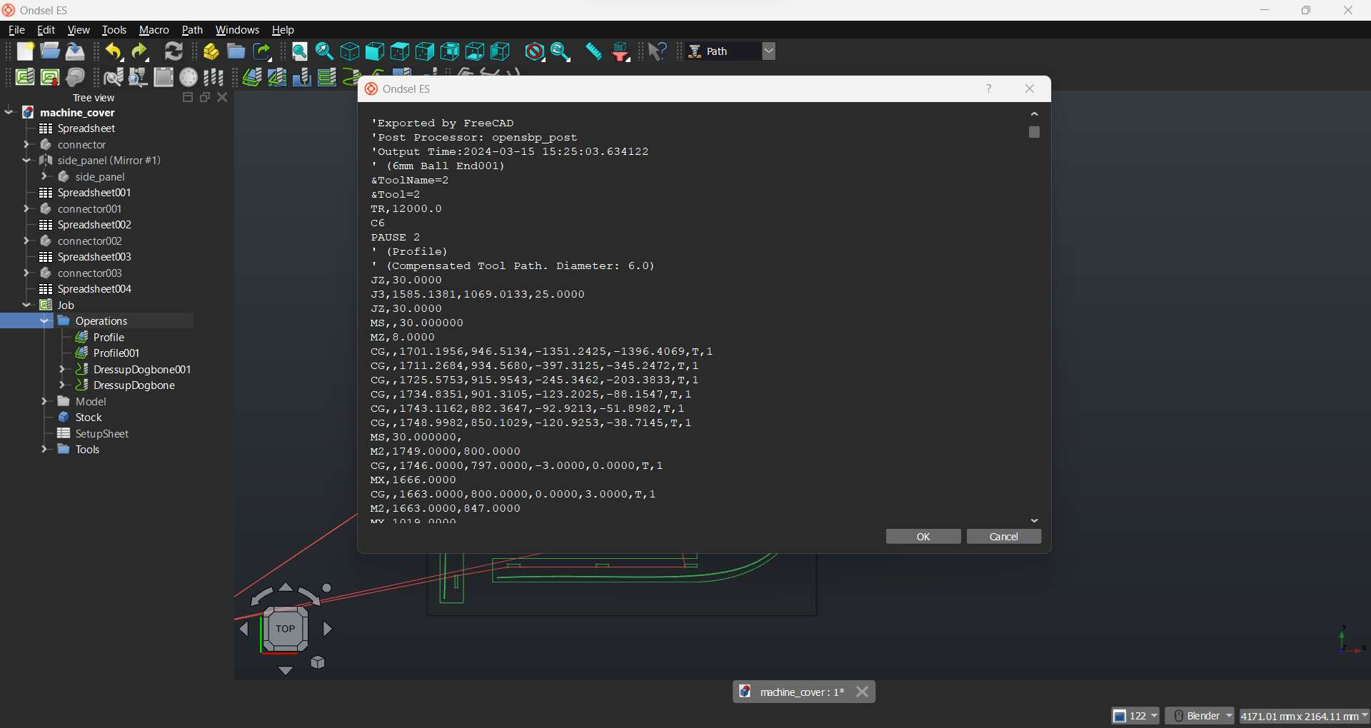
After completing the profiles I clicked on the Post Process button near the job creation button to export the G-code
The video bellow shows the simulated milling process
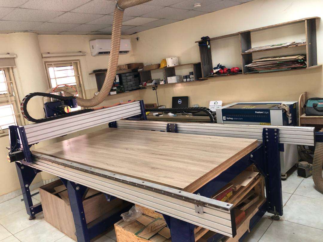
Our lab is equipped with a shopbot standard with a working area of 96x48 inches.
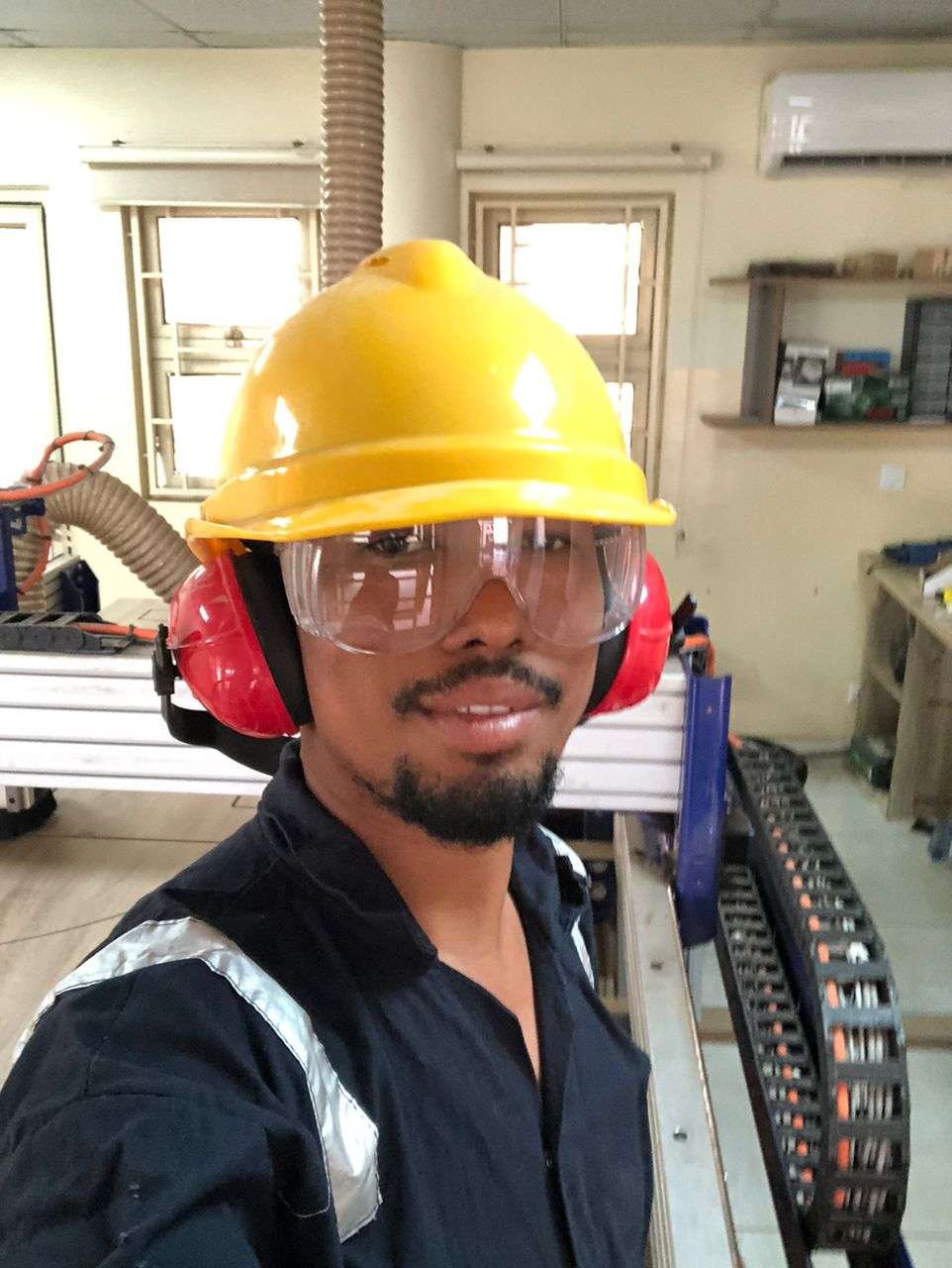
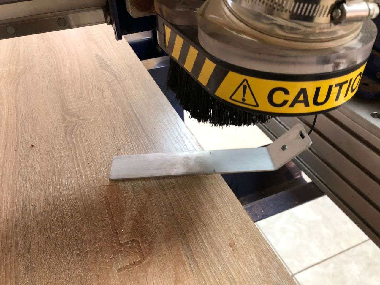
First thing first, before using the shopbot it is required that safety precautions be followed such as the use of goggles and ear cover
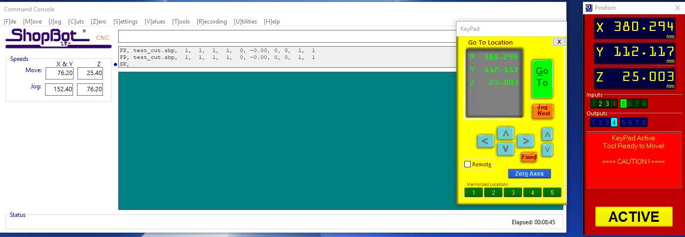
I used the Shopbot Control software to set the zero position in preparation for cutting
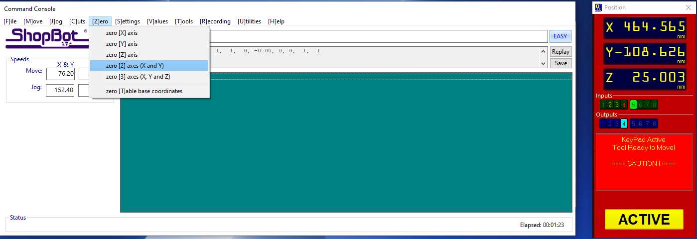
So, I moved the machine head to the point where I intend to set x,y zero position and selected “zero[Z] axes (X and Y)” from [Z]ero menu.
To set the zero position for the z axis I used the Zero plate provided and placed it on the surface of my stock.
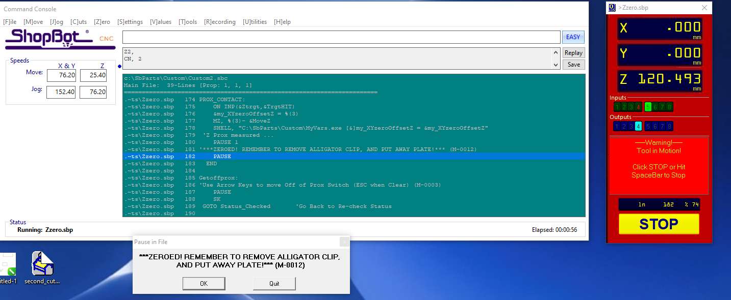
I then started the zero process. The machine moved the head until the bit torches the plate. That set the zero automatically.
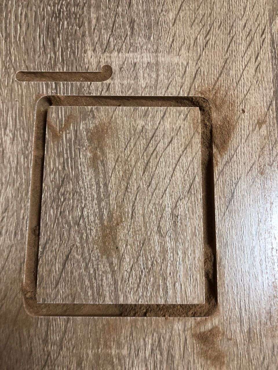
This is our first time to directly generate the path file from CAD (ondsel). Before now we used Aspire to design and create toolpaths. So to test this workflow, I designed a simple rectangle to serve as a test file.
After having success with the test cut, I loaded the my part file for cutting:
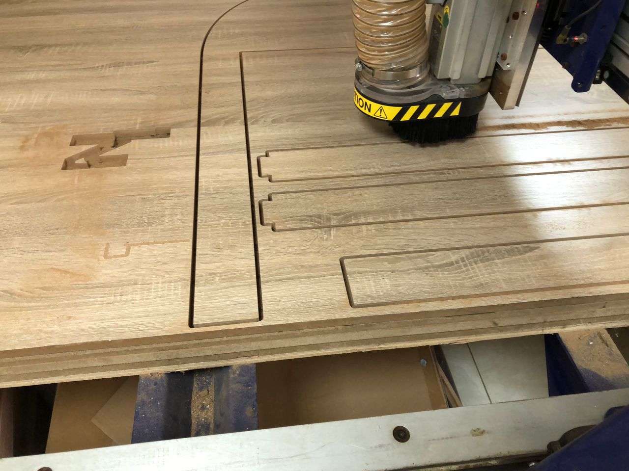
I used 30mm/s feed rate and a depth of 6mm per step when generating the paths.
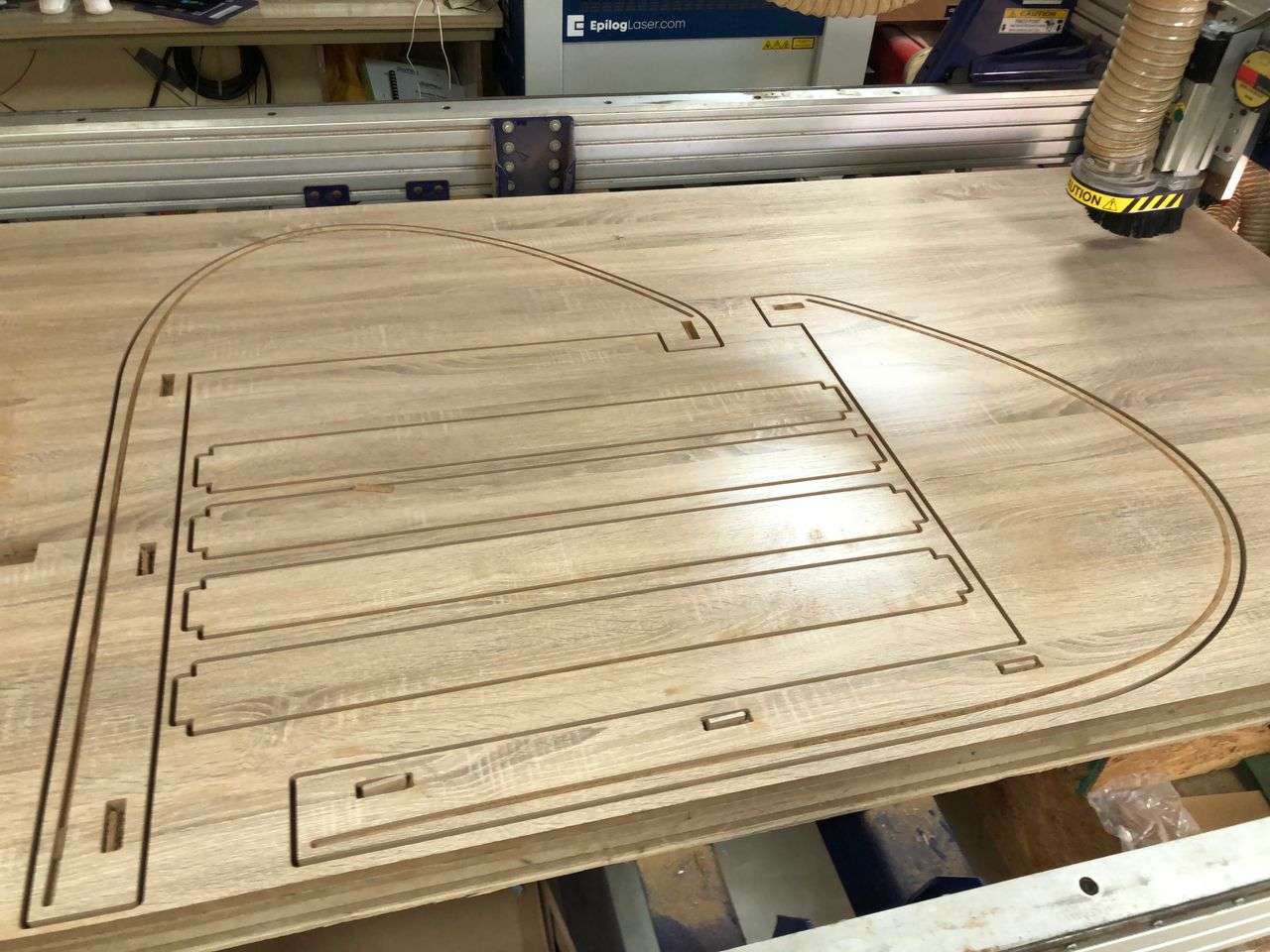
Assembly the part is easy because of the dogbone added to the joining parts
The our shopbot started acting weird after i tried using gcode generated from Ondsel toolpath. We later find out that the coordinate system was adjusted by the gcode. It took us about a week to fix this issue. We have attempted a lot of fixes such as updating the windows, updating the control software drivers etc. but the fix that worked is restoring the setting of the control software to factory settings. I later found out that Ondsel can export toolpaths to shopbot part file format. They call it opensbp
I cannot get a flexible cover that can easily slide into the groove of the machine cover. I tried with this 3mm wood sheet and it cannot easily enter the grooves. I also tried with 6mm corrugated cardboard but it failed. Therefore I am still looking for a flex cover that can slide easily to cover the machine.