11. Input devices
This week I worked on my final project’s input device’s part.
Group assignment
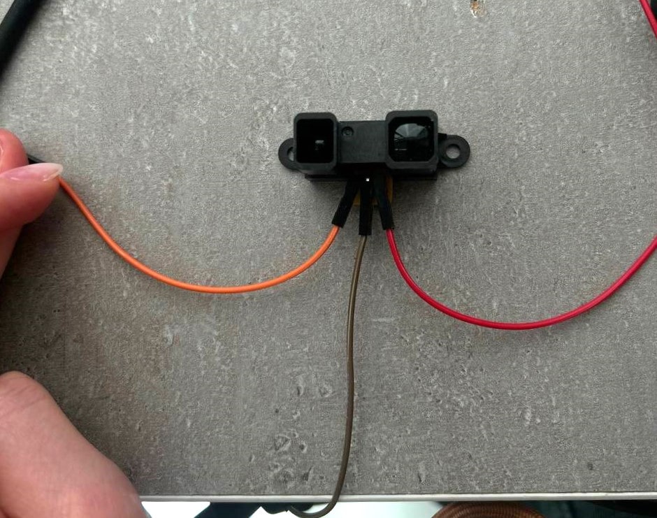
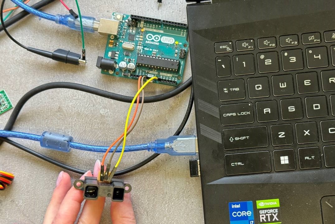
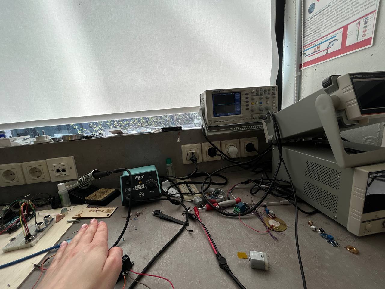
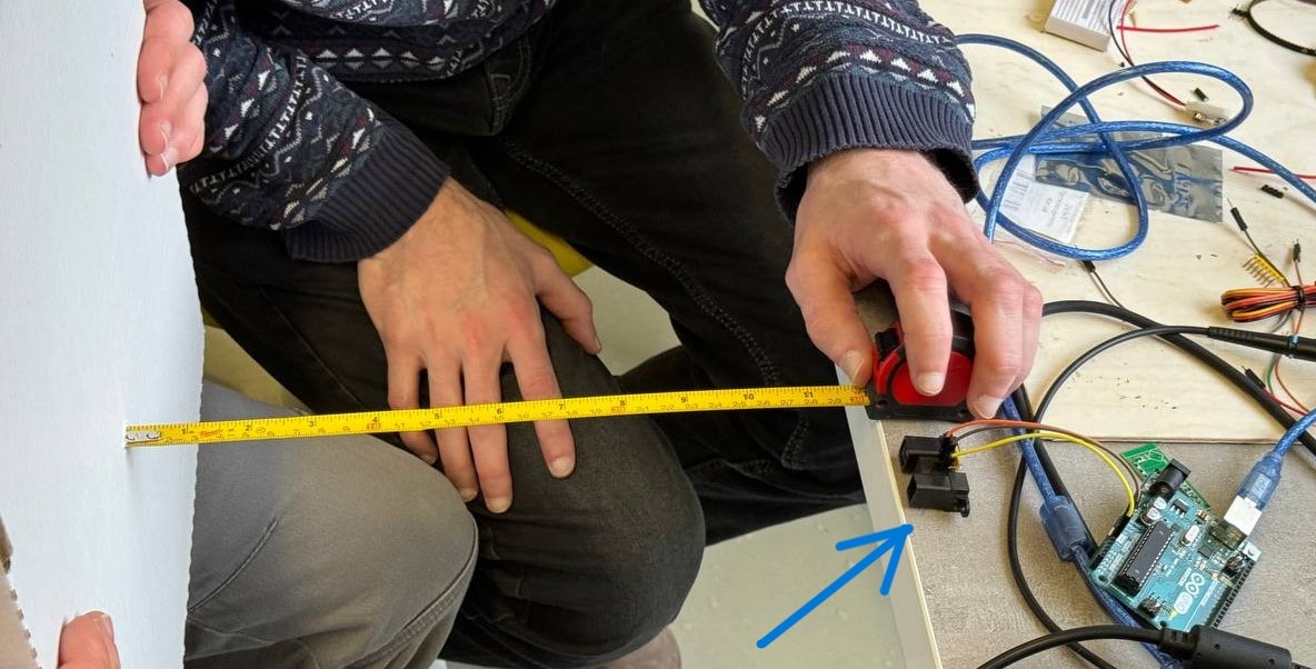
For this week’s group assignment we tried analog and digital sensors, especially Sharp GP2Y0A21YK0F and HC-SR04 Ultrasonic Sensor . First one is an analog Distance Measuring Sensor and the second one operates using digital signals.
We programmed this sensors by Arduino IDE.
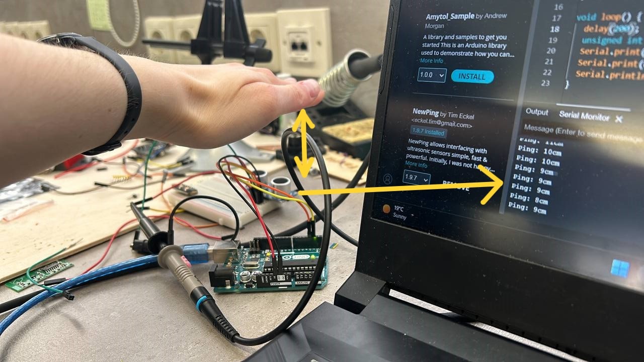
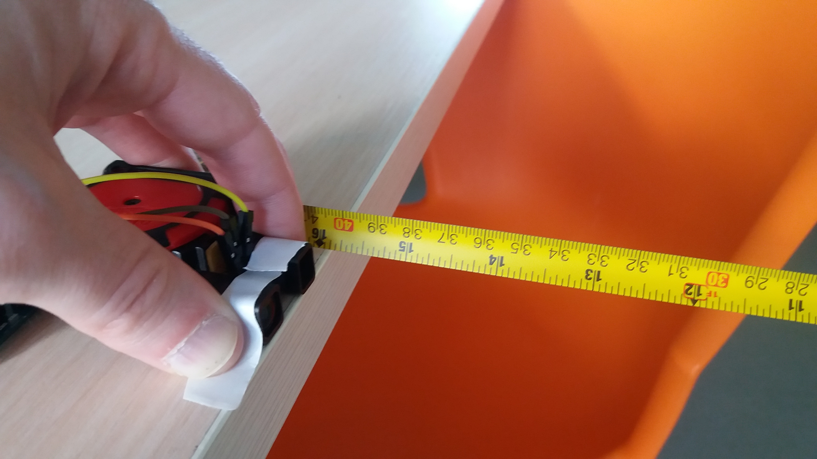
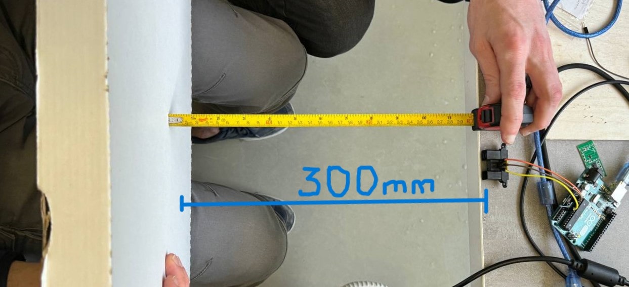
By turning on serial monitor we put the object in front of our sensors and saw the measurement numbers. After we compared this numbers with the original measures (we measured with meter).
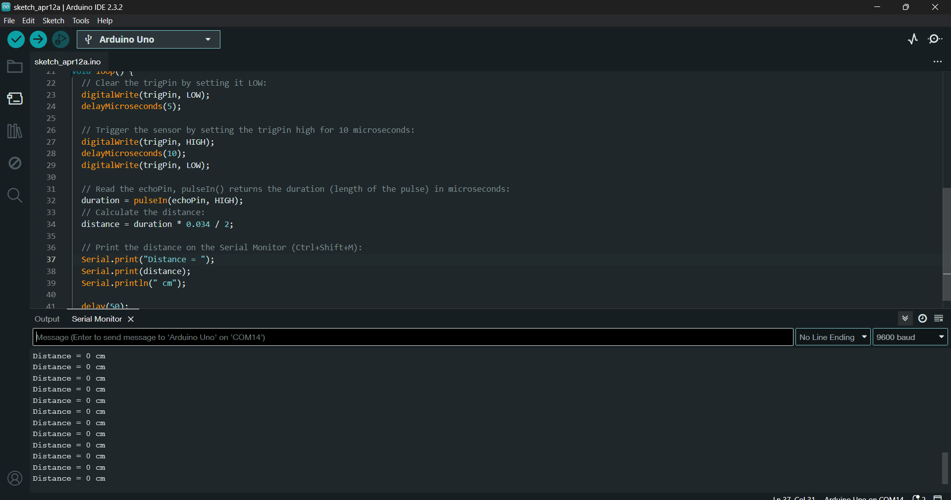
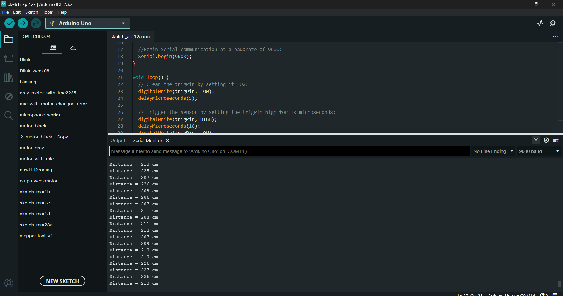
First code that we tried was much more accurate, it was near to original distance. It was written from the Example code for HC-SR04 with Arduino.
But after we tried the code with NewPing library, the readings were more accurate.
Example code for HC-SR04 ultrasonic distance sensor with Arduino
This is the very first code that we used to try 2 of our sensors:
- we need to know - do they work, do they measure and how accurately do they measure?
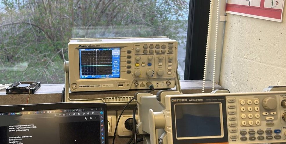
First code worked and showed distances with Sharp and with Ultrasonic.
We tried to see that with oscilloscope. And it showed clearly the distance on diagram.
/* Example code for HC-SR04 ultrasonic distance sensor with Arduino.
   No library required. More info: https://www.makerguides.com */

// Define Trig and Echo pin:
#define trigPin 2
#define echoPin 3

// Define variables:
long duration;
int distance;

void setup() {
  // Define inputs and outputs:
  pinMode(trigPin, OUTPUT);
  pinMode(echoPin, INPUT);

  //Begin Serial communication at a baudrate of 9600:
  Serial.begin(9600);
}

void loop() {
  // Clear the trigPin by setting it LOW:
  digitalWrite(trigPin, LOW);
  delayMicroseconds(5);

  // Trigger the sensor by setting the trigPin high for 10 microseconds:
  digitalWrite(trigPin, HIGH);
  delayMicroseconds(10);
  digitalWrite(trigPin, LOW);

  // Read the echoPin, pulseIn() returns the duration (length of the pulse) in microseconds:
  duration = pulseIn(echoPin, HIGH);
  // Calculate the distance:
  distance = duration * 0.034 / 2;

  // Print the distance on the Serial Monitor (Ctrl+Shift+M):
  Serial.print("Distance = ");
  Serial.print(distance);
  Serial.println(" cm");

  delay(50);
}
Maxime’s Code without library
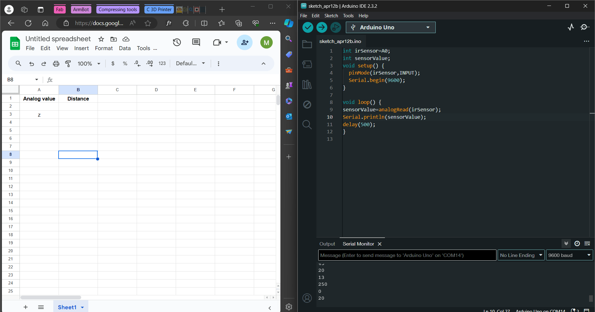
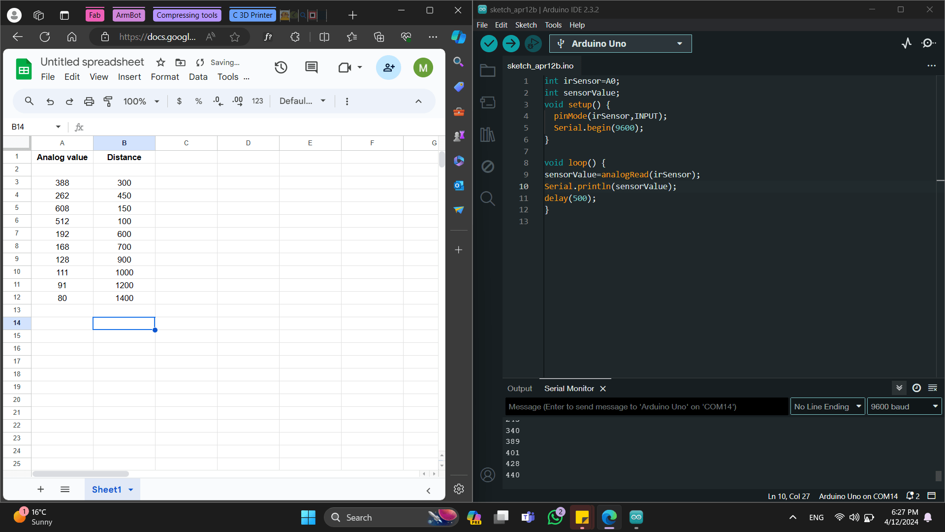
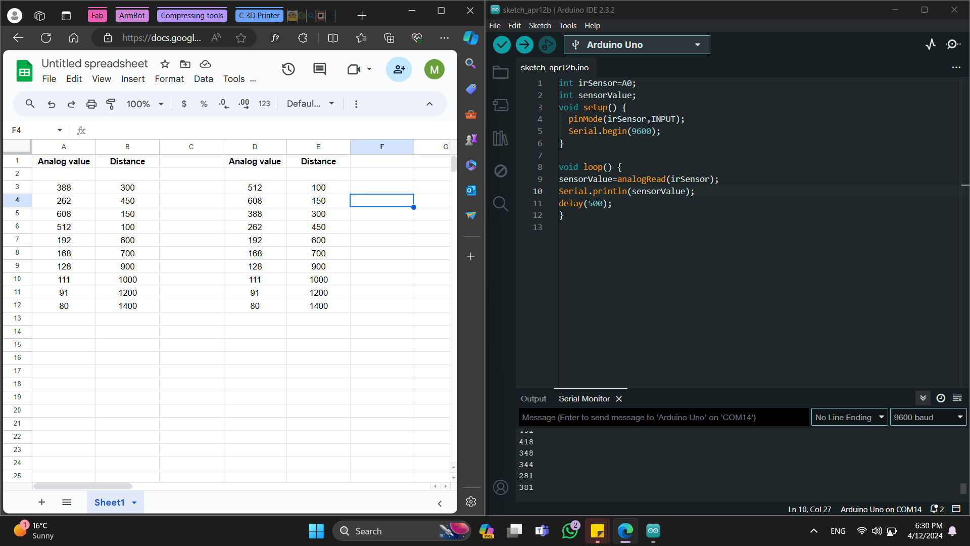
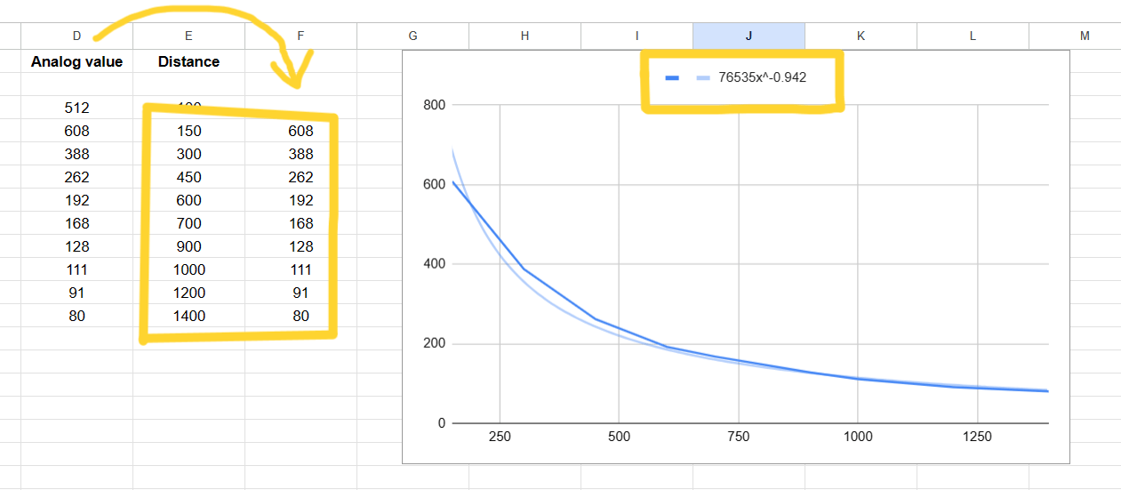
We recorded our data in an Excel spreadsheet, organizing it into two columns: one for analog values and the other for the corresponding distances we measured.
Using Excel, we created a chart to visualize the relationship between the sensor’s analog output voltage and distance.
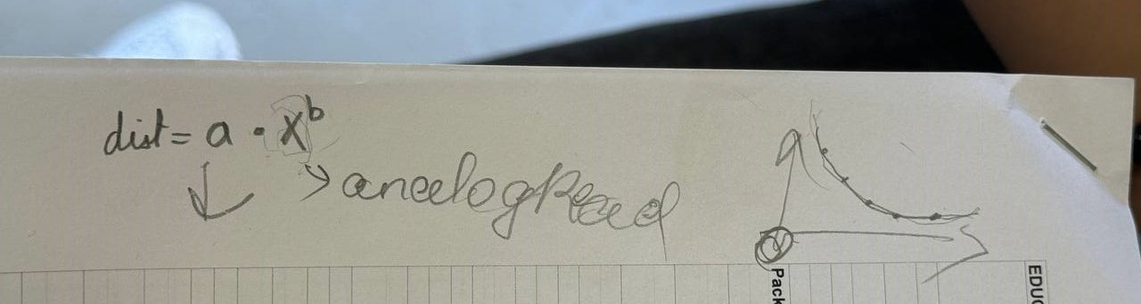
In our example, this relationship turned out to be nonlinear. Specifically, for the Sharp GP2Y0A21YK0F sensor, we approximated it with an exponential function. The function we derived was - [ f(x) = 145712x^{-1.05} ]
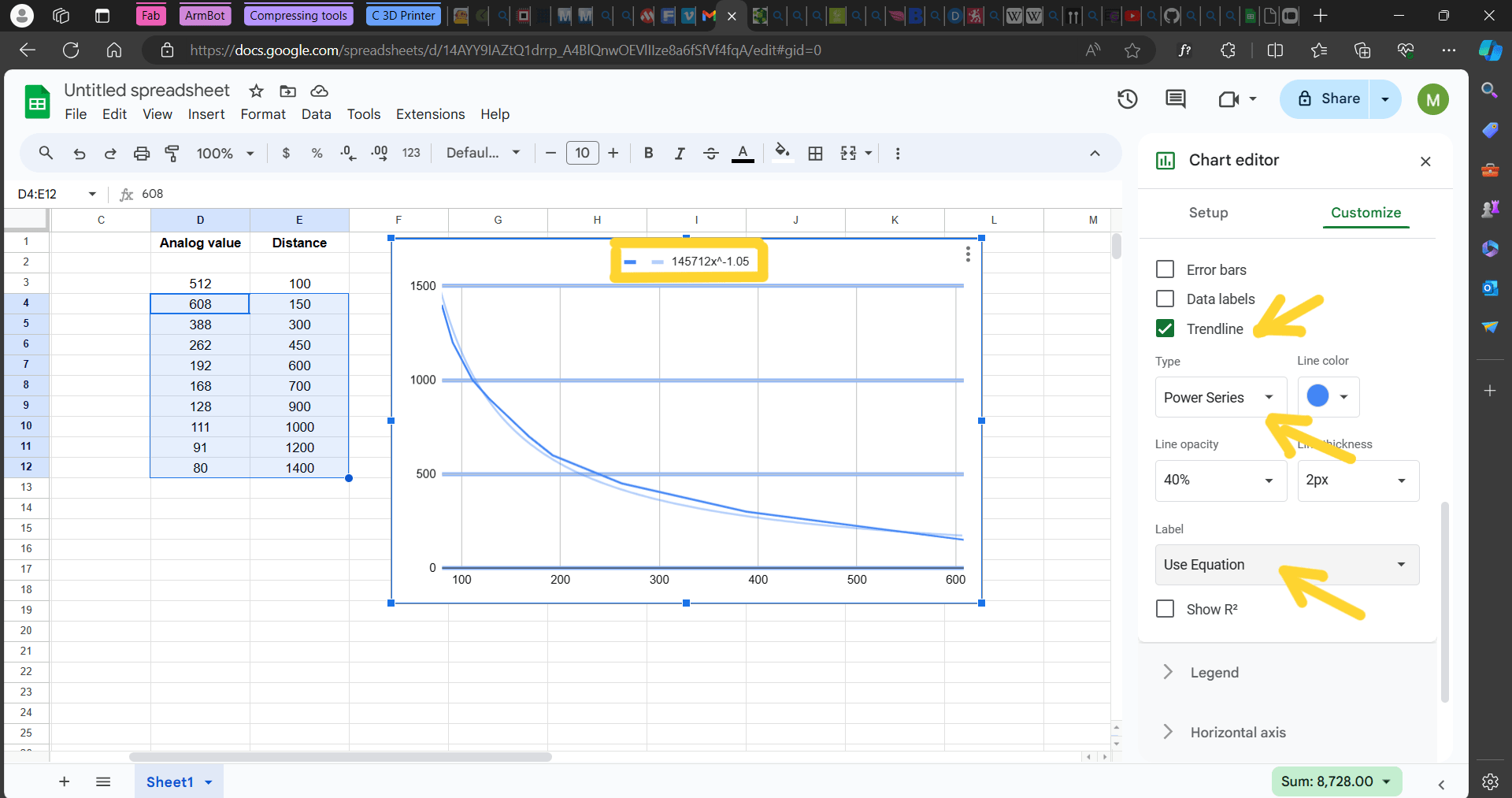
We then implemented this function in our code. However, during testing, we encountered issues—the code didn’t work as expected. To troubleshoot, we decided to switch the order of columns in Excel. But the only problem was that we forgot the minus in front of the 1.05.
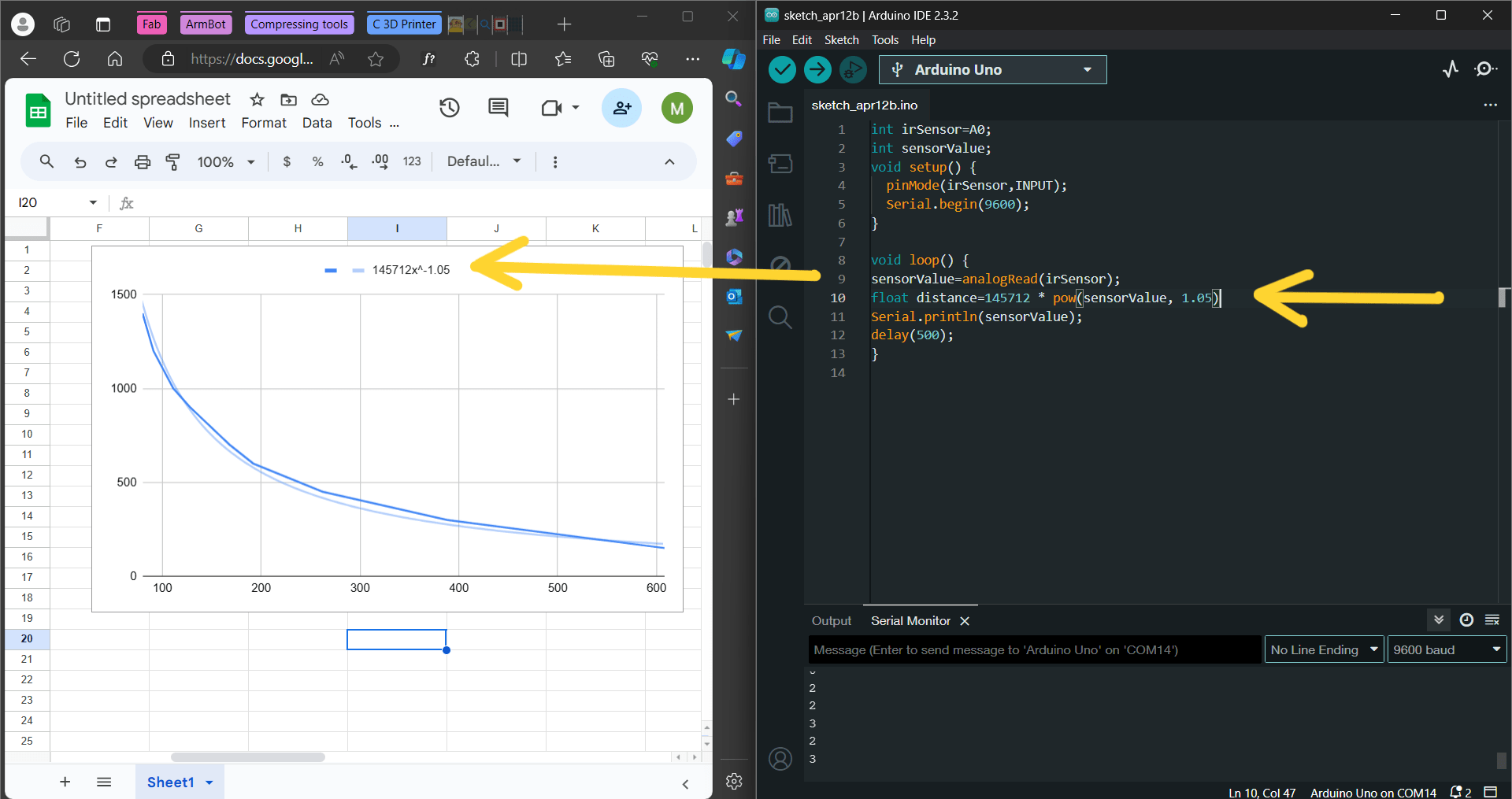
But the only problem was that we forgot the minus in front of the 1.05.
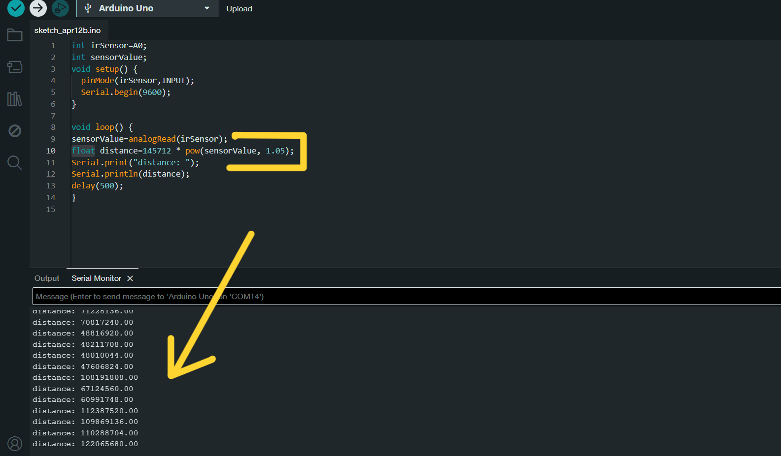
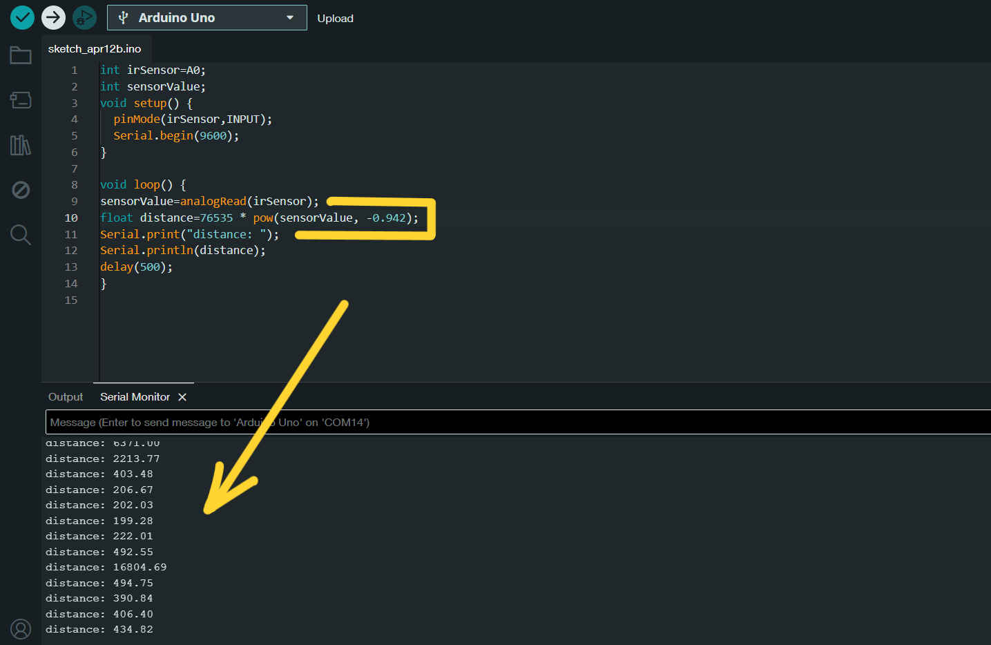
For that we improved the function in our code and get this numbers.
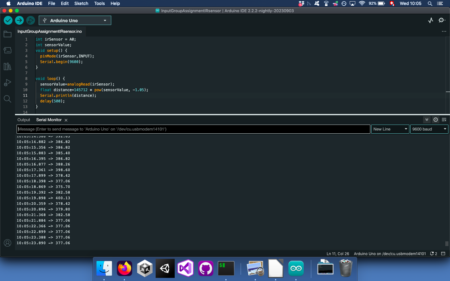
Aftet, we placed the distance values before the analog readings. The new function became: - [ f(x) = 76535x^{-0.942} ]
As I searched for this function and what it means, I learned that:
[ f(x) = 76535x^{-0.942} ]
- (f(x)): This represents the output value (in this case, the analog voltage) corresponding to a given input value (x) (which represents distance).
- (x): The input variable, which represents the distance. It could be the distance measured by your sensor.
- 76535: This is a constant coefficient. It determines the overall scale of the function. In other words, it affects how steep or shallow the curve will be.
- (-0.942): The exponent itself. It’s a negative value, which means that as (x) increases, the function value decreases. The magnitude of the exponent (0.942) determines how quickly the function changes with respect to (x).
Although the modified code worked, it still lacked precision. Possible factors contributing to this discrepancy include ambient light, noise interference, or the need for additional measurements.
We tried to change this number 76535x^ to 8500. It made a little bit change to better measurment. Numbers were similar to the right distance.
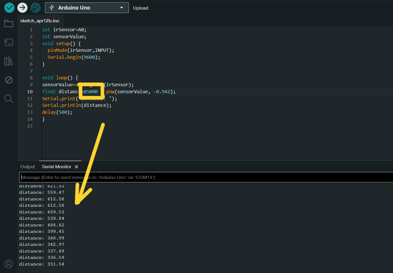
And here is the code that we used.
int irSensor=A0;
int sensorValue;
void setup() {
  pinMode(irSensor,INPUT);
  Serial.begin(9600);
}

void loop() {
sensorValue=analogRead(irSensor);
float distance=85000 * pow(sensorValue, -0.942);
Serial.print("distance: ");
Serial.println(distance);
delay(500);
}
Code with NewPing library
New Ping library made a difference. It was much more accurate.
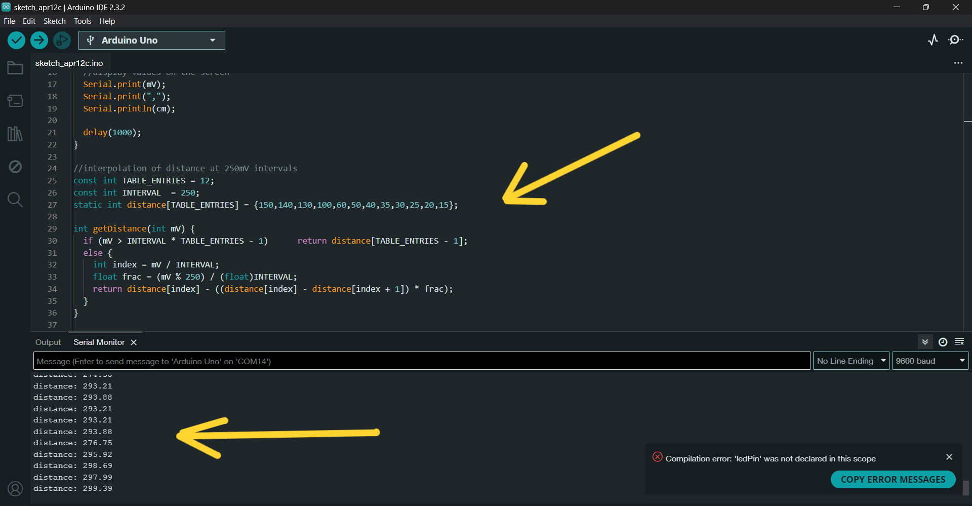
With this library, the code has shown much more accurate information.
const int sensorPin = A0;
const long referenceMv = 5000;

void setup() {
  Serial.begin(9600);
  pinMode(ledPin, OUTPUT);
}

void loop() {
  //reading the voltage
  int val = analogRead(sensorPin);
  int mV = (val * referenceMv) / 1023;
  int cm = getDistance(mV);


  //display values on the screen
  Serial.print(mV);
  Serial.print(",");
  Serial.println(cm);

  delay(1000);
}

//interpolation of distance at 250mV intervals
const int TABLE_ENTRIES = 12;
const int INTERVAL  = 250;
static int distance[TABLE_ENTRIES] = {150,140,130,100,60,50,40,35,30,25,20,15};

int getDistance(int mV) {
  if (mV > INTERVAL * TABLE_ENTRIES - 1)      return distance[TABLE_ENTRIES - 1];
  else {
    int index = mV / INTERVAL;
    float frac = (mV % 250) / (float)INTERVAL;
    return distance[index] - ((distance[index] - distance[index + 1]) * frac);
  }
}
Individual assignment
TCS3472 color sensor
For one of my individual assignments I tried to work with the TCS3472 color sensor. This is a color light-to-digital converter equipped with an IR blocking filter.
IR (Infrared) blocking filter is a component which helps to block or minimize infrared wavelengths and allow visible light to pass through. As a result, it brings to color accuracy.
So TCS3472 has Red, Green, Blue (RGB), and Clear Light Sensing: The TCS3472 provides digital values for these color channels.
I asked COPILOT to provide me with some information about this device:
RGB LED Backlight Control: Ideal for adjusting backlight colors.
Light Color Temperature Measurement: Useful for determine lighting conditions.

Ambient Light Sensing (ALS): Enables automatic display brightness adjustments in devices like cell phones, TVs, notebooks.

Product Color Verification and Sorting: Useful in industrial processes.

Solid State Lighting (SSL) and Digital Signage.

Health/Fitness Products, Medical Diagnostic Equipment, and more.
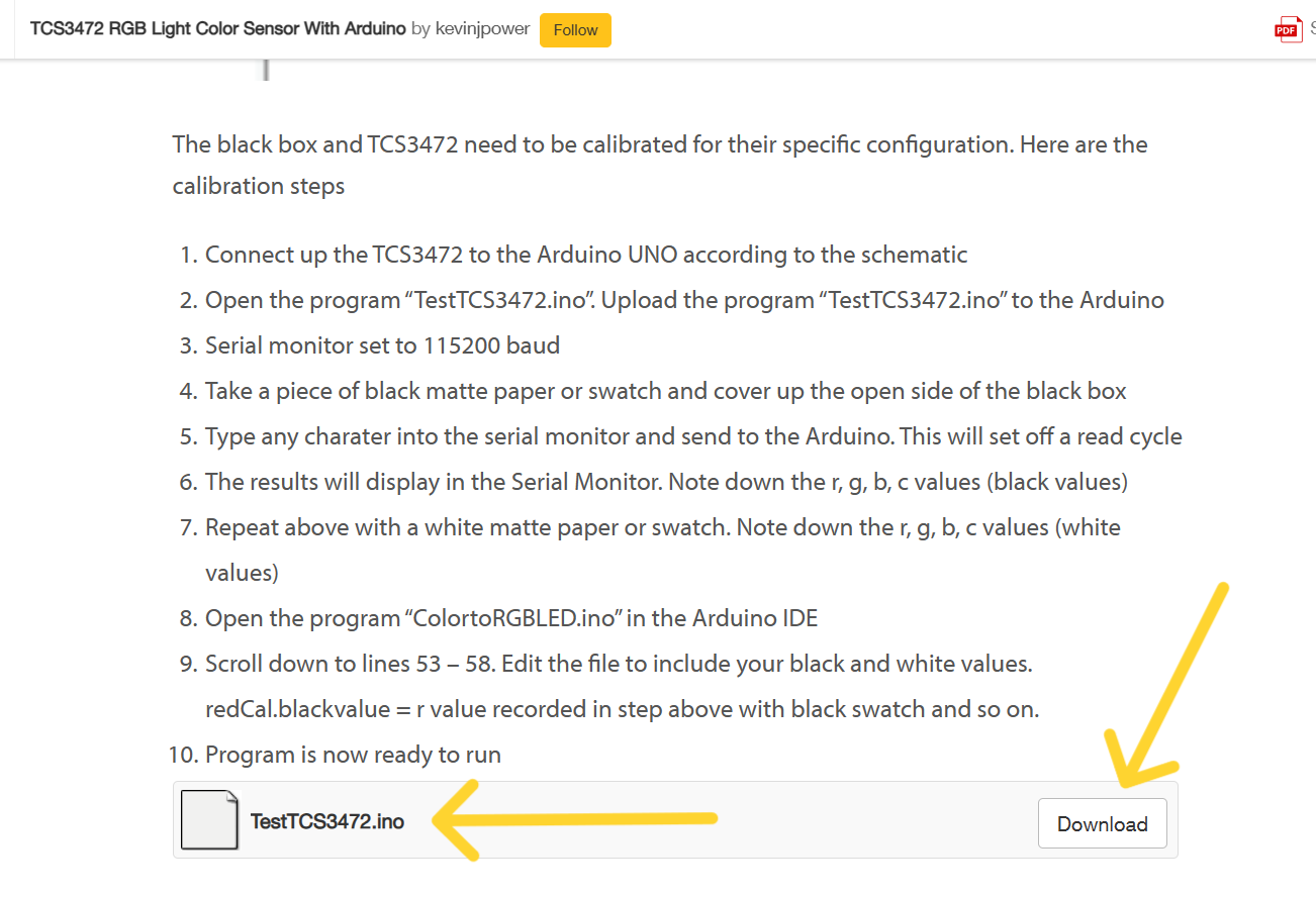
The guideline of TCS3472 RGB Light Color Sensor With Arduino helped me a lot in this experience.
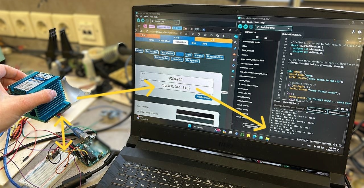
After connecting all, I found the code, that could be helpful, for experimenting with this sensor. - RGB Light Color Sensor With Arduino
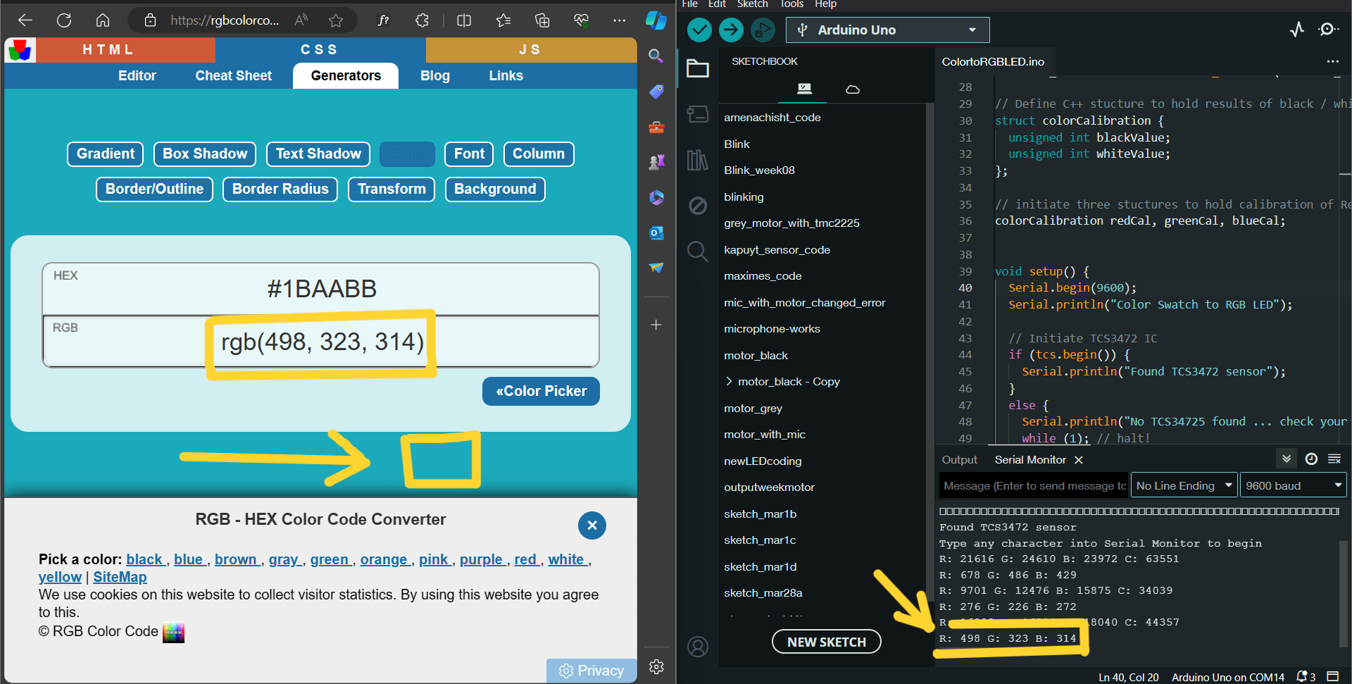
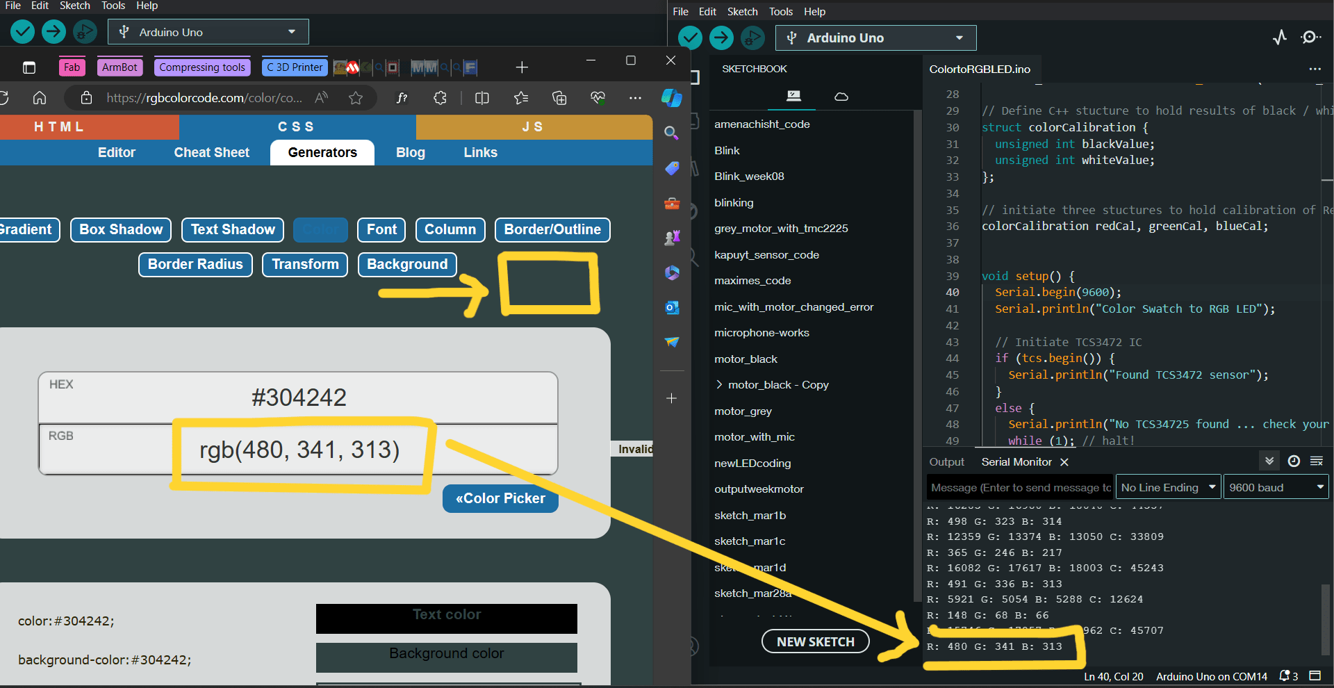
By downloading and opening it in Arduino IDE I made my first try and hold a blue object in front of the sensor. In serial monitor it started to write RGB code numbers,
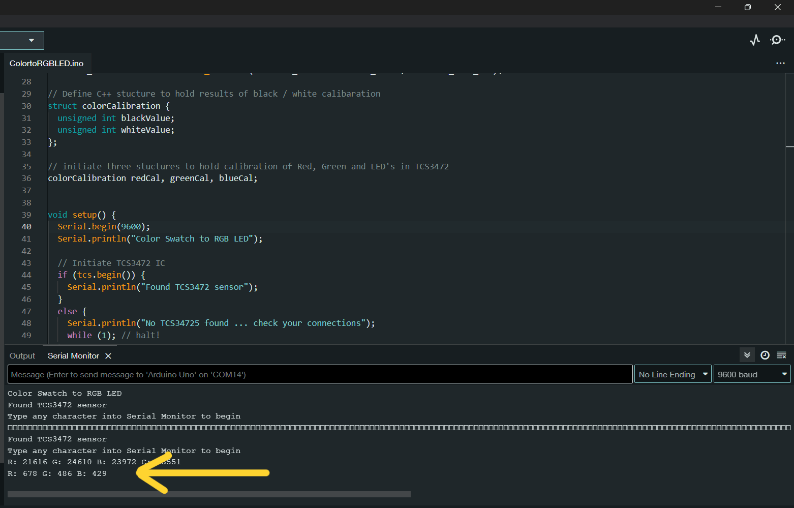
Which I was able to decode in this website, where you can type RGB numbers and it will give the color shade.
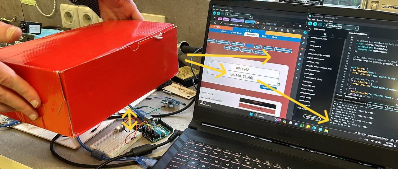
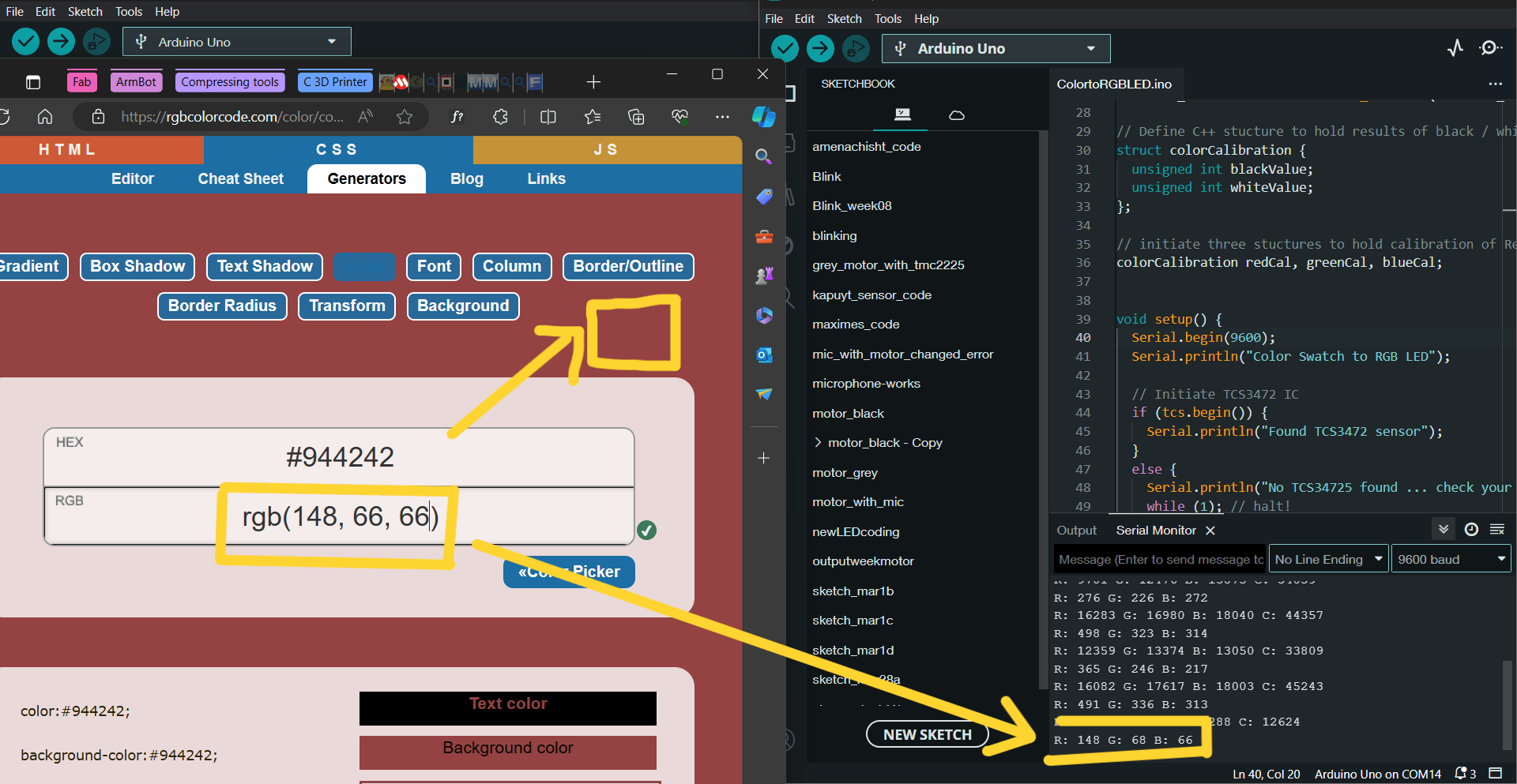
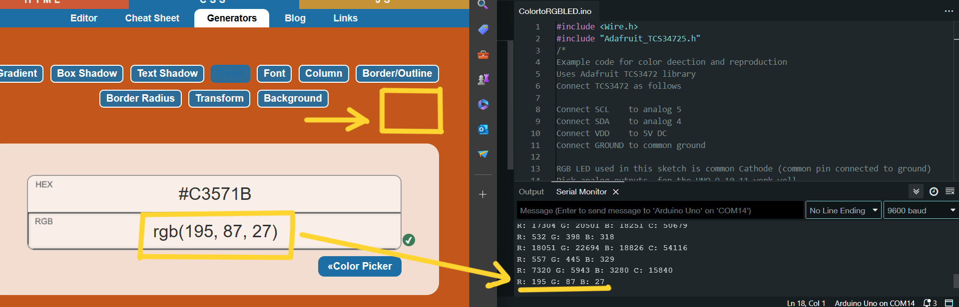
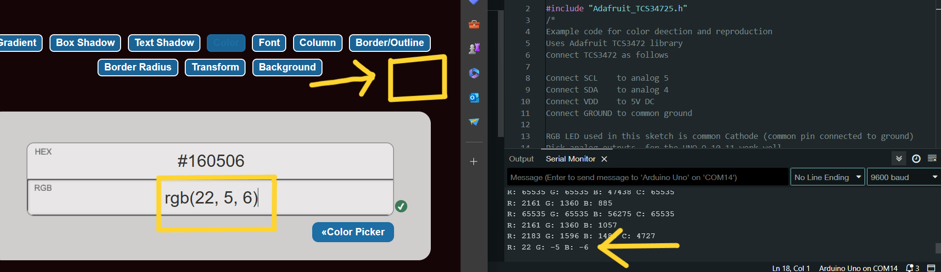
After I tried this with red, blue, black and yellow objects.
#include <Wire.h>
#include "Adafruit_TCS34725.h"
/*
Example code for color direction and reproduction
Uses Adafruit TCS3472 library
Connect TCS3472 as follows

Connect SCL    to analog 5
Connect SDA    to analog 4
Connect VDD    to 5V DC
Connect GROUND to common ground

RGB LED used in this sketch is common Cathode (common pin connected to ground)
Pick analog outputs, for the UNO 9,10,11 work well
Use 220 Ohm / 1kOhm resistors between supply and RGB LED
See schematic for connections
*/

const int redpin = 9;
const int greenpin = 10;
const int bluepin = 11;

// array to represent the gamma function
int gammatable[256];

// Initalize an object 'tcs" with integration time 600 ms and gain 16X
Adafruit_TCS34725 tcs = Adafruit_TCS34725(TCS34725_INTEGRATIONTIME_600MS, TCS34725_GAIN_16X);

// Define C++ structure to hold results of black / white calibaration
struct colorCalibration {
  unsigned int blackValue;
  unsigned int whiteValue;
};

// initiate three structures to hold calibration of Red, Green and LED's in TCS3472
colorCalibration redCal, greenCal, blueCal;


void setup() {
  Serial.begin(9600);
  Serial.println("Color Swatch to RGB LED");

  // Initiate TCS3472 IC
  if (tcs.begin()) {
    Serial.println("Found TCS3472 sensor");
  }
  else {
    Serial.println("No TCS34725 found ... check your connections");
    while (1); // halt!
  }

  // These values result from calibration of the TCS3472 looking at a black sample and a white sample
  // Must be edited here once calibration values have been determined
  redCal.blackValue = 1525;
  redCal.whiteValue = 9078;
  greenCal.blackValue = 1851;
  greenCal.whiteValue = 13787;
  blueCal.blackValue = 1847;
  blueCal.whiteValue = 14972;

  // use these three pins to drive an RGB LED
  pinMode(redpin, OUTPUT);
  pinMode(greenpin, OUTPUT);
  pinMode(bluepin, OUTPUT);

  // Gamma function is Out = In^2.5
  // Required to correct for human vision
  // Store values in an array
  // normalized for 0 to 255
  for (int i=0; i<256; i++) {
    float x = i;
    x /= 255;
    x = pow(x, 2.5);
    x *= 255;

    gammatable[i] = int(x);
    }

  Serial.println("Type any character into Serial Monitor to begin");
}


void loop() {
  unsigned int r, g, b, c; // raw values of r,g,b,c as read by TCS3472
  // Variables used to hold RGB values between 0 and 255
  int redValue;
  int greenValue;
  int blueValue;
  int clearValue;
  // Dummy string used to read in input from serial monitor
  String incomingString;

  delay(500);

  // Typing any character into Serial Monitor will kick off a read / output cycle
  if (Serial.available() > 0){
    incomingString = Serial.readString();
    // Get raw data from the TCS3472
    tcs.getRawData(&r, &g, &b, &c);

    // Print out raw data resulting from read cycle
    Serial.print("R: "); Serial.print(r); Serial.print(" ");
    Serial.print("G: "); Serial.print(g); Serial.print(" ");
    Serial.print("B: "); Serial.print(b); Serial.print(" ");
    Serial.print("C: "); Serial.print(c); Serial.print(" ");
    Serial.println(" ");

    delay(50);

    // Convert TCS3472 raw reading into value between 0 and 255 for analogwrite function
    redValue = RGBmap(r, redCal.blackValue, redCal.whiteValue, 0, 255);
    greenValue = RGBmap(g, greenCal.blackValue, greenCal.whiteValue, 0, 255);
    blueValue = RGBmap(b, blueCal.blackValue, blueCal.whiteValue, 0, 255);

    // Print out values
    Serial.print("R: "); Serial.print(redValue); Serial.print(" ");
    Serial.print("G: "); Serial.print(greenValue); Serial.print(" ");
    Serial.print("B: "); Serial.print(blueValue); Serial.print(" ");
    Serial.println(" ");

    // Write out values to RGB LED
    // Gamma function applied to raw values
    analogWrite(redpin, gammatable[redValue]);
    analogWrite(greenpin, gammatable[greenValue]);
    analogWrite(bluepin, gammatable[blueValue]);

  }

}

// Function to map TCS3472 values to 0 to 255
// Same as Arduino map() function - rewritten to make variables compatible with inputs and outputs
int RGBmap(unsigned int x, unsigned int inlow, unsigned int inhigh, int outlow, int outhigh){
  float flx = float(x);
  float fla = float(outlow);
  float flb = float(outhigh);
  float flc = float(inlow);
  float fld = float(inhigh);

  float res = ((flx-flc)/(fld-flc))*(flb-fla) + fla;

  return int(res);
}
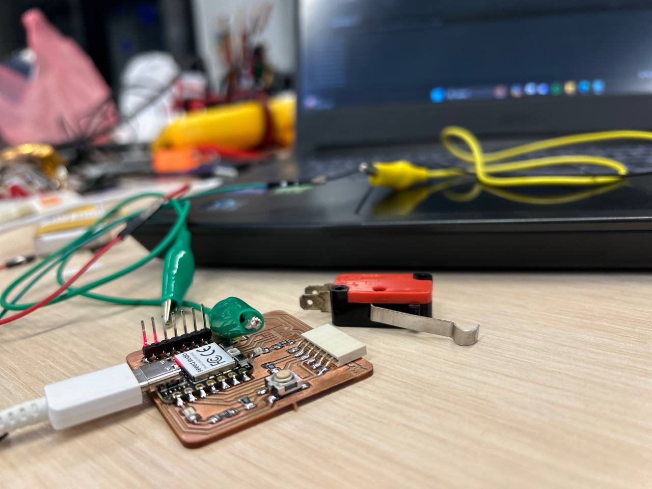
V-154-1C25 end switch
As an input device I used an end switch, and programmed it. It is commonly used as a limit switch or a position sensor.
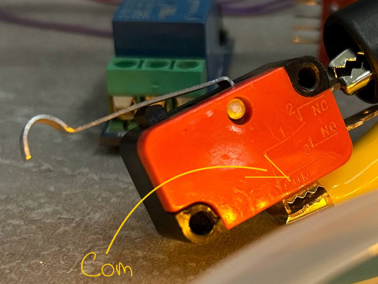
| V-154-1C25 has three pins |
|---|
| 1. VCC: It provides the necessary voltage for the switch to operate. - 5V power |
| 2. GND: This pin is connected to the ground. |
| 3. Signal: This pin is used to read the switch state. You can connect it to any digital pin to detect the switch status. |
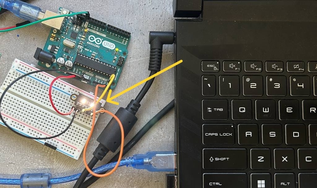
In photo below you can see the switch and it’s pins, which are connected to the power and turned on the LED.
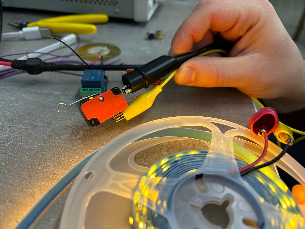
Here you can see how it works. I powered it with 12V.
Also by changing turned on pins locations, we can make it work vice versa. - It will turn on lights when switch is not pressed.
So after trying it in work, I started programming process by my AT Tiny 1614 microcontroller using Atmel-ICE programmer.
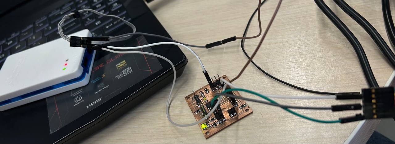
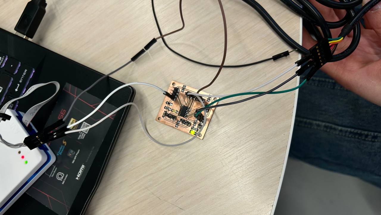
But it was problematic for me, and after some hours when I didn’t find the problem of not programming the AT Tiy, I changed my board and used RP2040 microcontroller.
One of the switch’s pins I connected to my microcontroller’s GND pin, and the other one to a digital pin, which is the 2nd pin in Arduino.
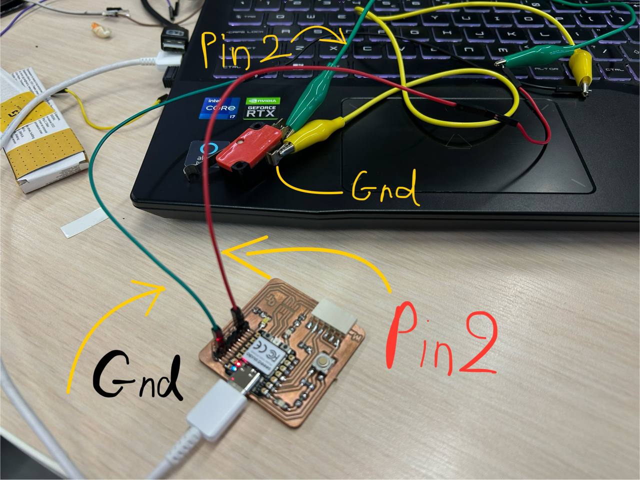
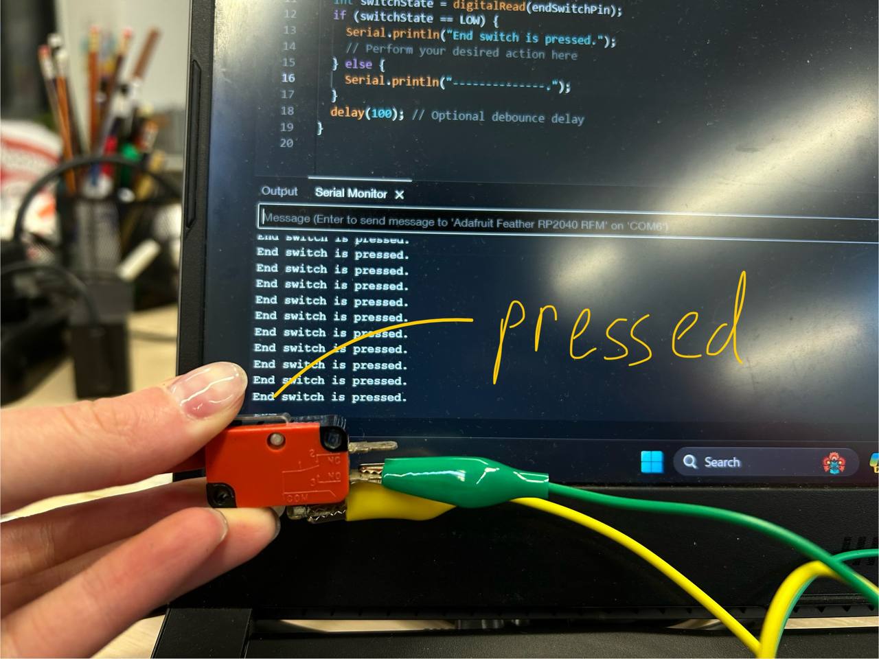
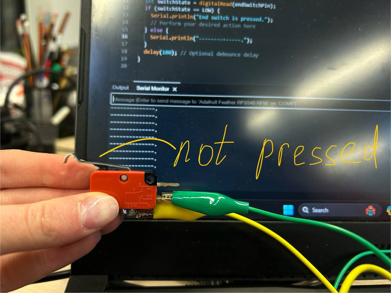
And using this pin, I asked COPILOT to write a code for me, by which I will see the process in serial monitor.
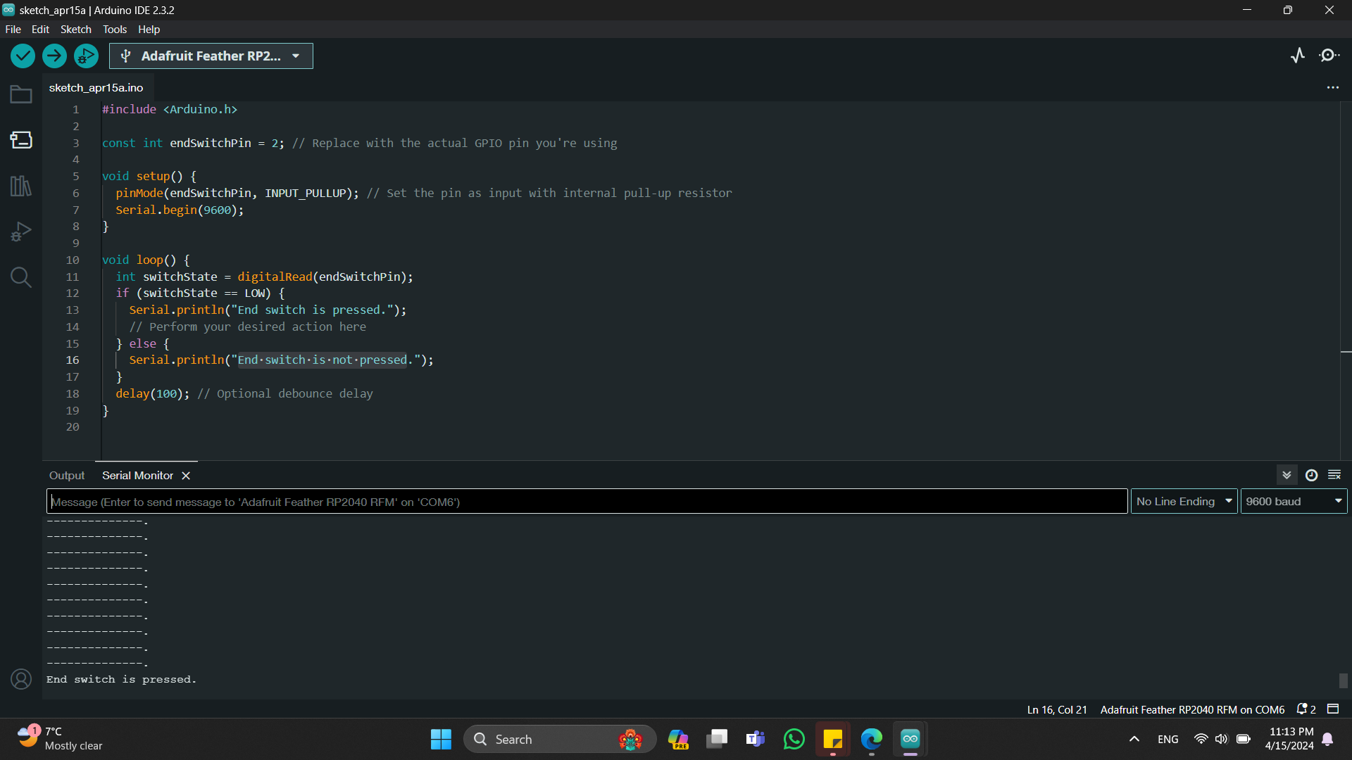
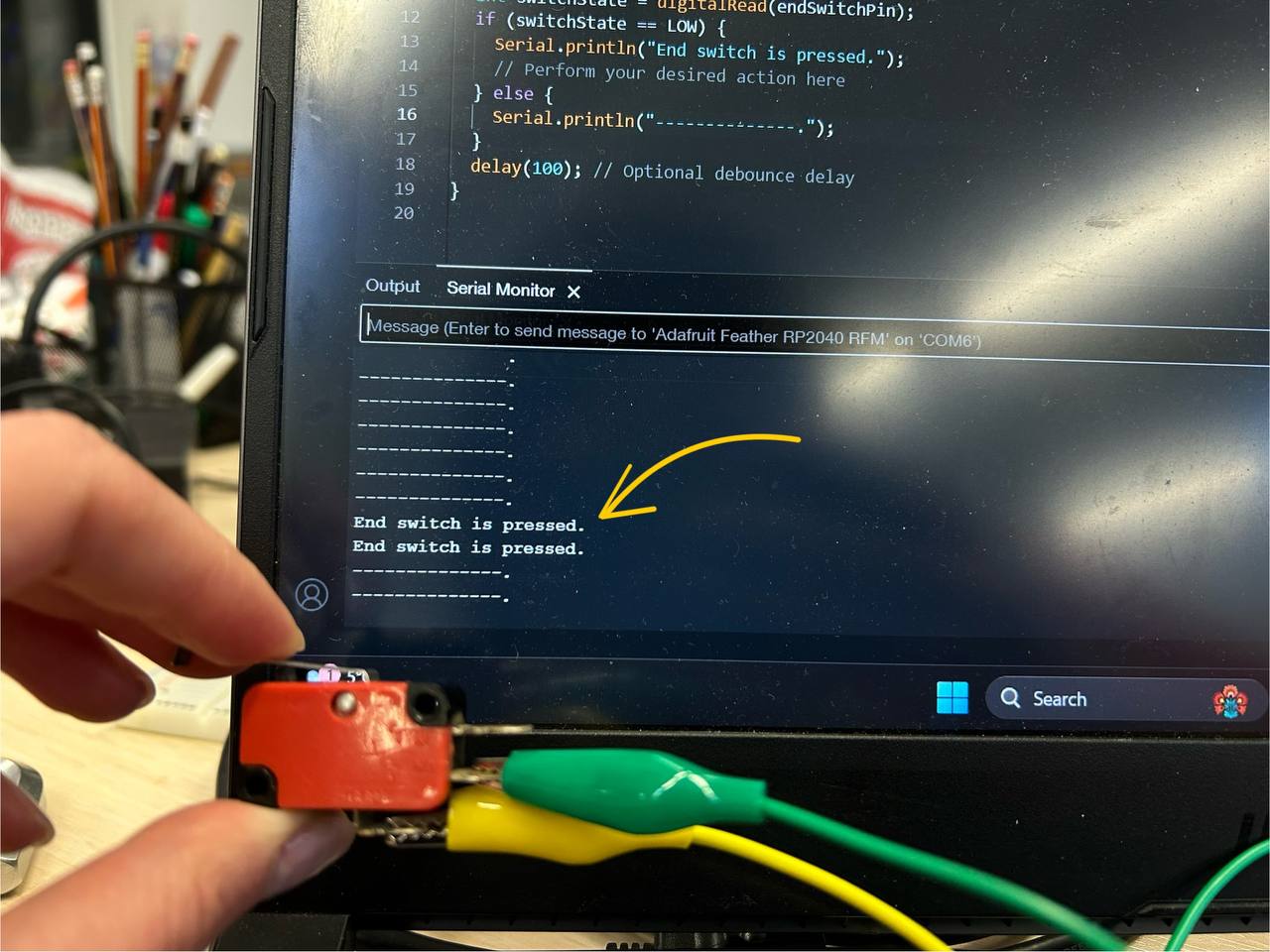
As you can see, in previous pushed code I changed Serial.println("End switch is not pressed."); this sentence to Serial.println("----------------");
Because of that you can see in picture below this sentences.
#include <Arduino.h>

const int endSwitchPin = 2; // Replace with the actual GPIO pin you're using

void setup() {
  pinMode(endSwitchPin, INPUT_PULLUP); // Set the pin as input with internal pull-up resistor
  Serial.begin(9600);
}

void loop() {
  int switchState = digitalRead(endSwitchPin);
  if (switchState == LOW) {
    Serial.println("End switch is pressed.");
    // Perform your desired action here
  } else {
    Serial.println("End switch is not pressed.");
  }
  delay(100); // Optional debounce delay
}
Conclusion
This week was more or less calm for me after MACHINE BUILDING WEEK! We did a great group assignment with Maxime. In my final project I will need this type of sensors, so it was very informative for me. The things that I will need are distance measurement sensor, color detector sensor and end switch will be also needed.
Also by programming this type of devices it was more clear for me to write code. I start to understand C++ better. The only sad part was that I couldn’t program the end switch with my own designed board - with AT Tiny 1614 microcontroller, but that could be from some wires, not from board.
It was less challenging for me, compared to output week, but I liked this week not less than the others.