9. Output devices
This week we learned about output devices and tried to program them. For that I used a stepper motor, as in my project I will use it.
Group Assignment
As part of a group assignment we explored many things with our instructor and master of his work Onik Babajanyan.
We look at motor types and how they work. We studied pulse width modulation. Also, regarding the DC motor that has + and - wires coming out of it. You give power and it spins. You change the places of + and - and the motor starts rotating in the opposite direction.
But if you want Dc motor to rotate at a specific speed, you set the voltage to 12V. It rotates fast at a stable speed. and for more fast rotation you set the voltage to 15V. How fast it will rotate depends on the voltage.
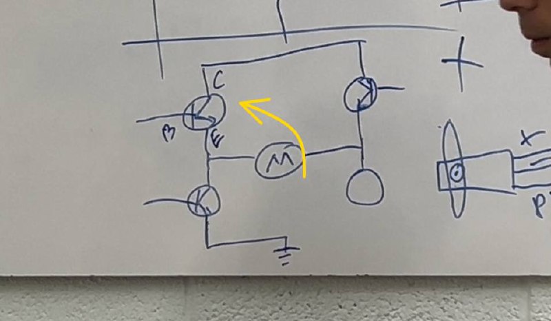
Then we put a transistor. Transistor has 3 pins and it is a semiconductor device that can amplify or switch electrical signals and power. The transistor takes some of the weight off the converter. And also in this case you cannot change the direction of the motor.
There are 2 types of semiconductors in a transistor. By connecting P and N type semiconductors, we get a diode. The transistor has an emitter collector and a base.
Semiconductors are of the positive type, where there are a lot of positive particles, and negative, where there are a lot of electrons. With different combinations, different components are obtained.
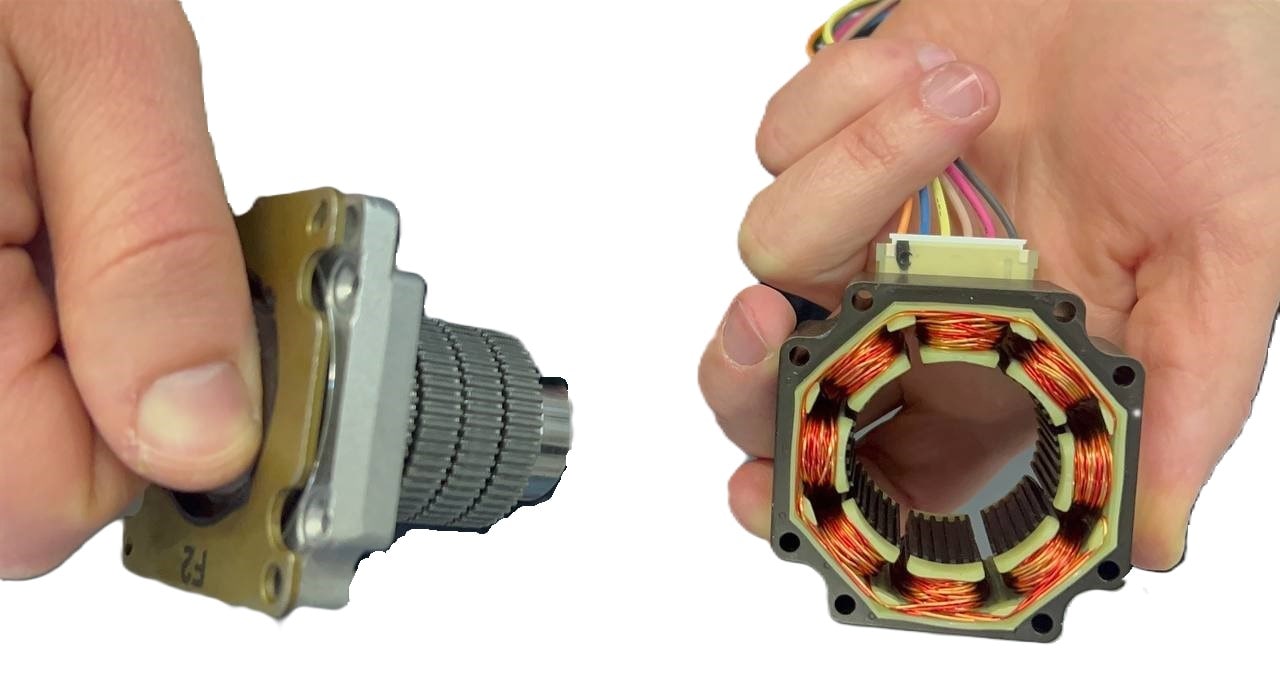
After Onik talked about Power Consumption. We took a stepper motor as an output device.
We needed to measure Power Consumption of DC motor. How much power does it use? In this case we need a bench power supply. It is a source of direct current. We put 12 volts with it, the maximum current that will allow to pass, we put 3.20 amperes.
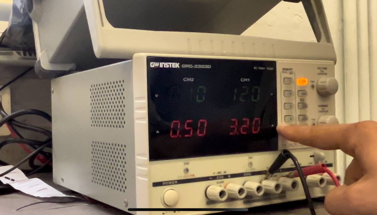 3.20 amperes is the maximum power that it allows. Connect the motor’s pins and press the “OUTPUT” button.
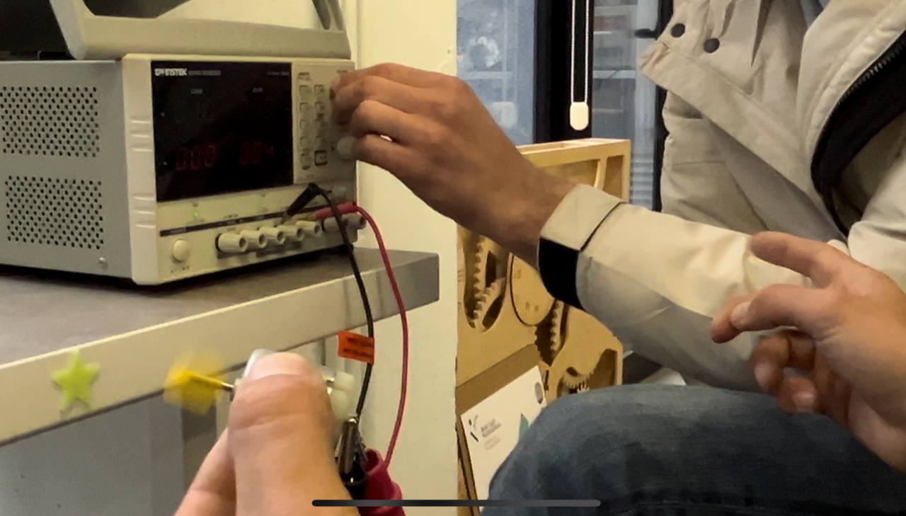
the motor starts to work, to rotate. Areg reduced the voltage from the power supply and the motor started to rotate slowly.
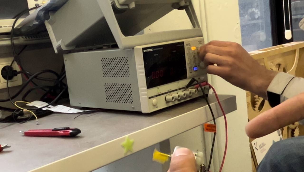
Then, paying attention, we see that the direction is counter-clockwise. Changing the + and - pins places, it starts to rotate in the opposite direction.
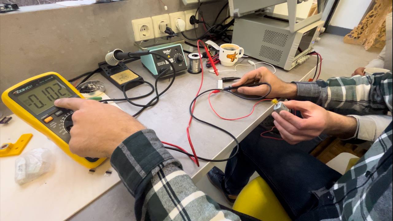
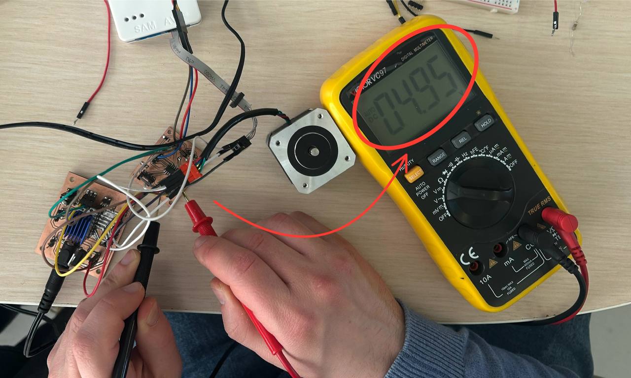
Then, to check with a multimeter, we set it to measure, put it on + and - and compare the numbers obtained from the 2 devices.
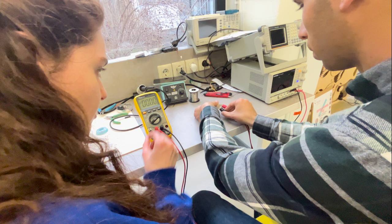
0.046Amp with multimeter, 0.03-0.04Amp with device. A multimeter measures more accurately.
After, by holding the shaft of the motor, we tested, that motor starts warming, because of the load. At first DC motor was rotating at 5V but after pressure voltage was growing up. It needed resistor, so that motor could not spent much current.
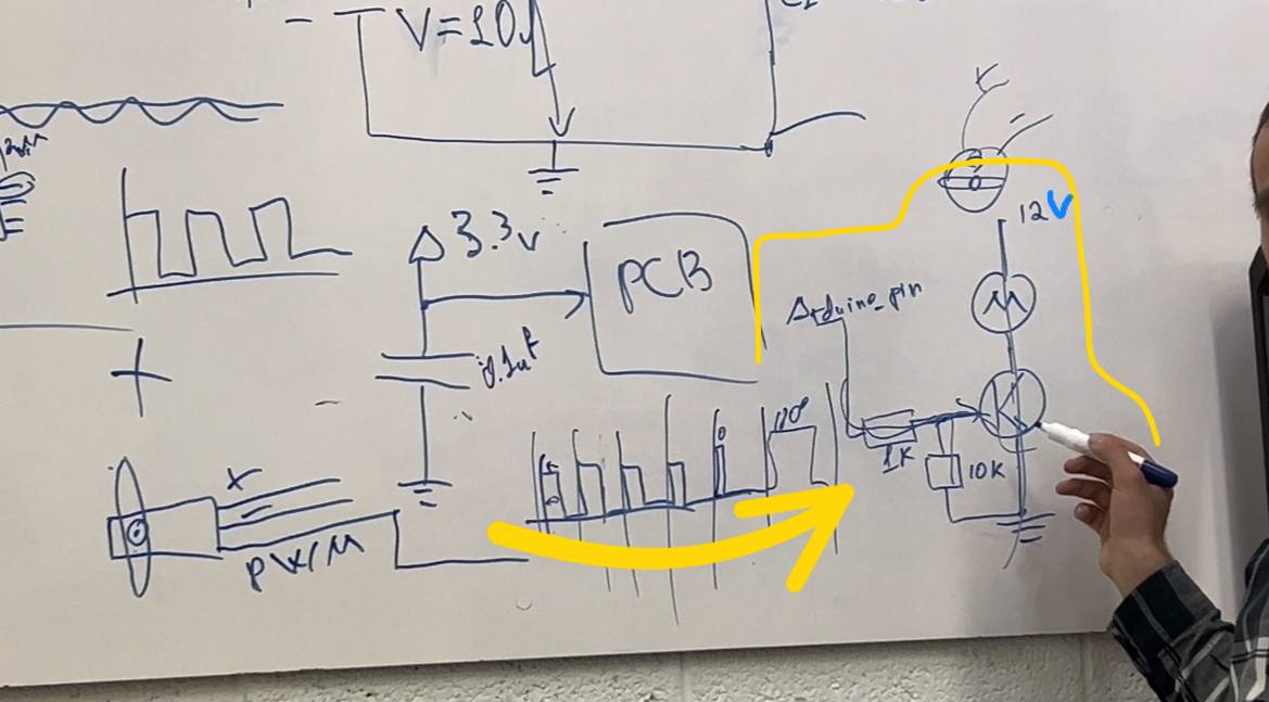
So after we tried the same with resistor. Resistance of the DC motor is 12 Ohm. Wen we connect motor with resistor current should decrease as we add to this resistance 1.8 Ohm resistor. And so we measured voltage - it was 0.1V. It’s a voltage on resistor.
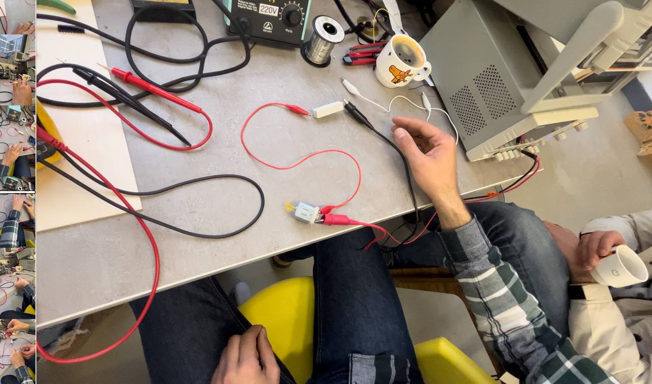
The main idea of Onik was to connect a DC motor, a resistor, to the Arduino board’s pin, so that the Arduino board will continuously measure this 0.1V. Resistance will go up, voltage will be more, Arduino will understand that there is an obstacle. The difference between unloaded and loaded is 0.1-0.2. We need to understand if the Arduino is able to accurately measure and give that difference. If it cannot, then the voltage should be artificially increased, multiplied by some constant, for example 10 times, and in that case Arduino will give us the correct calculation. And we will do the multiplication process with an operational amplifier.
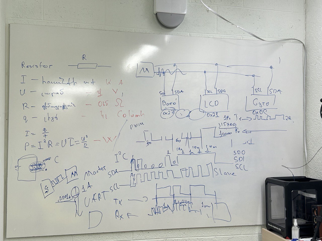
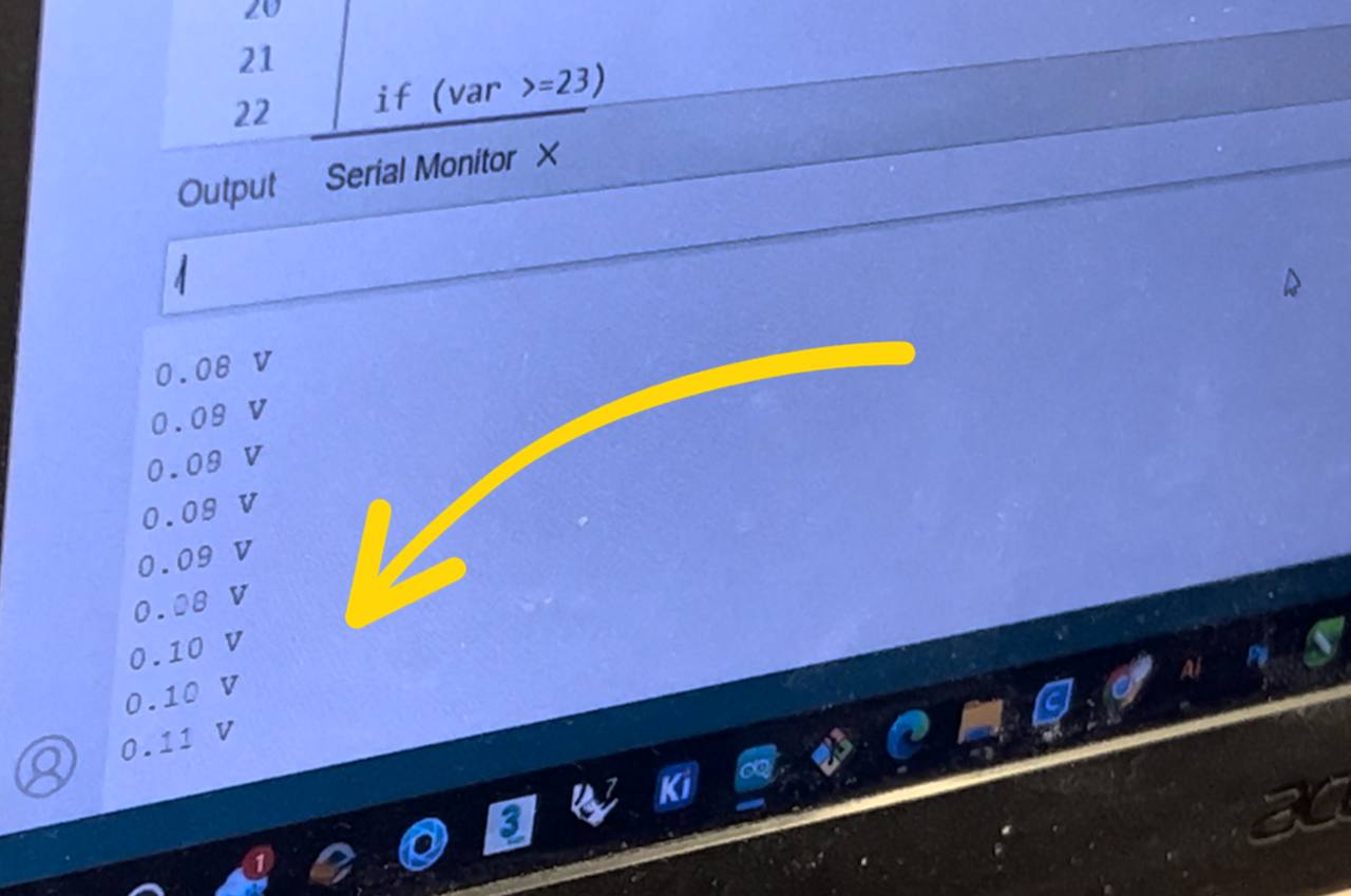
Thus, we instructed the Arduino to connect with the computer via URT (RX and TX). In Serial Monitor we chose 115200 in serial. Begin to measure it with that frequency. We wrote ՝՝՝int var = AnalogReadSensor՝՝՝. We connected A0 pin to the resistor and wrote it to do analogRead.
After that, we wrote Serial.Print, do that value, that is, print it. If there is a voltage here, then that voltage is displayed on the number 0 to 1023. 0 corresponds to 0 Volts, 1023 to 5 Volts. 5 / 1023 = 0.048 That is, the lowest voltage is this much, with this accuracy it can give us info. 0.1 Volt is on the resistor with a multimeter, 0.1 / 0.048 = 17/19/20
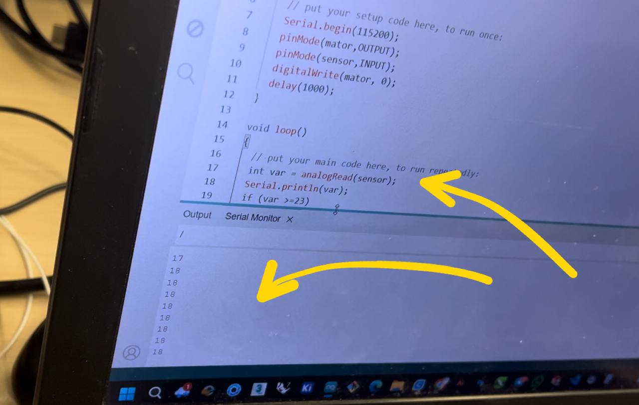
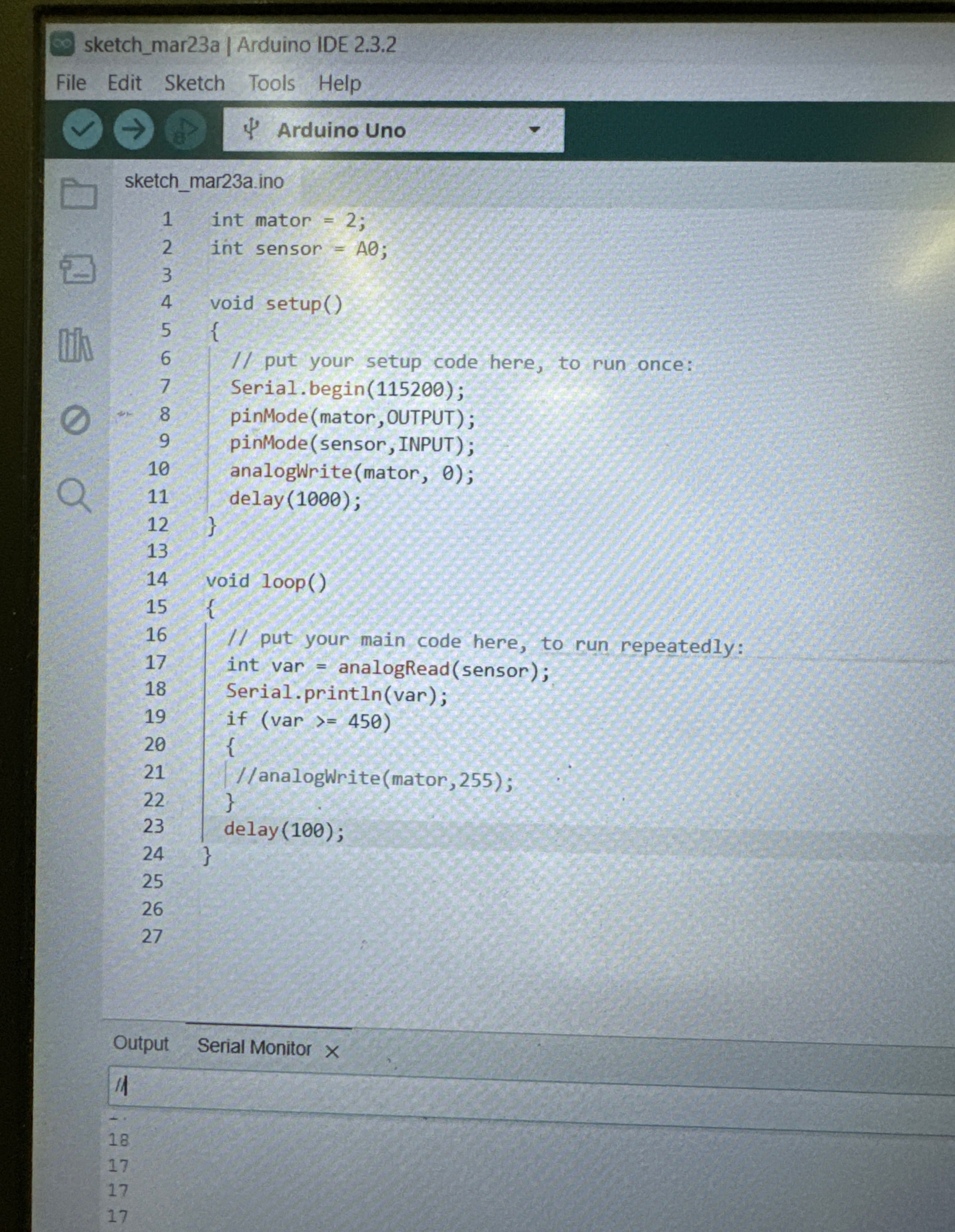
Arduino gives us the same numbers in the calculation. But so that we don’t do this calculation ourselves, we write it in our code.
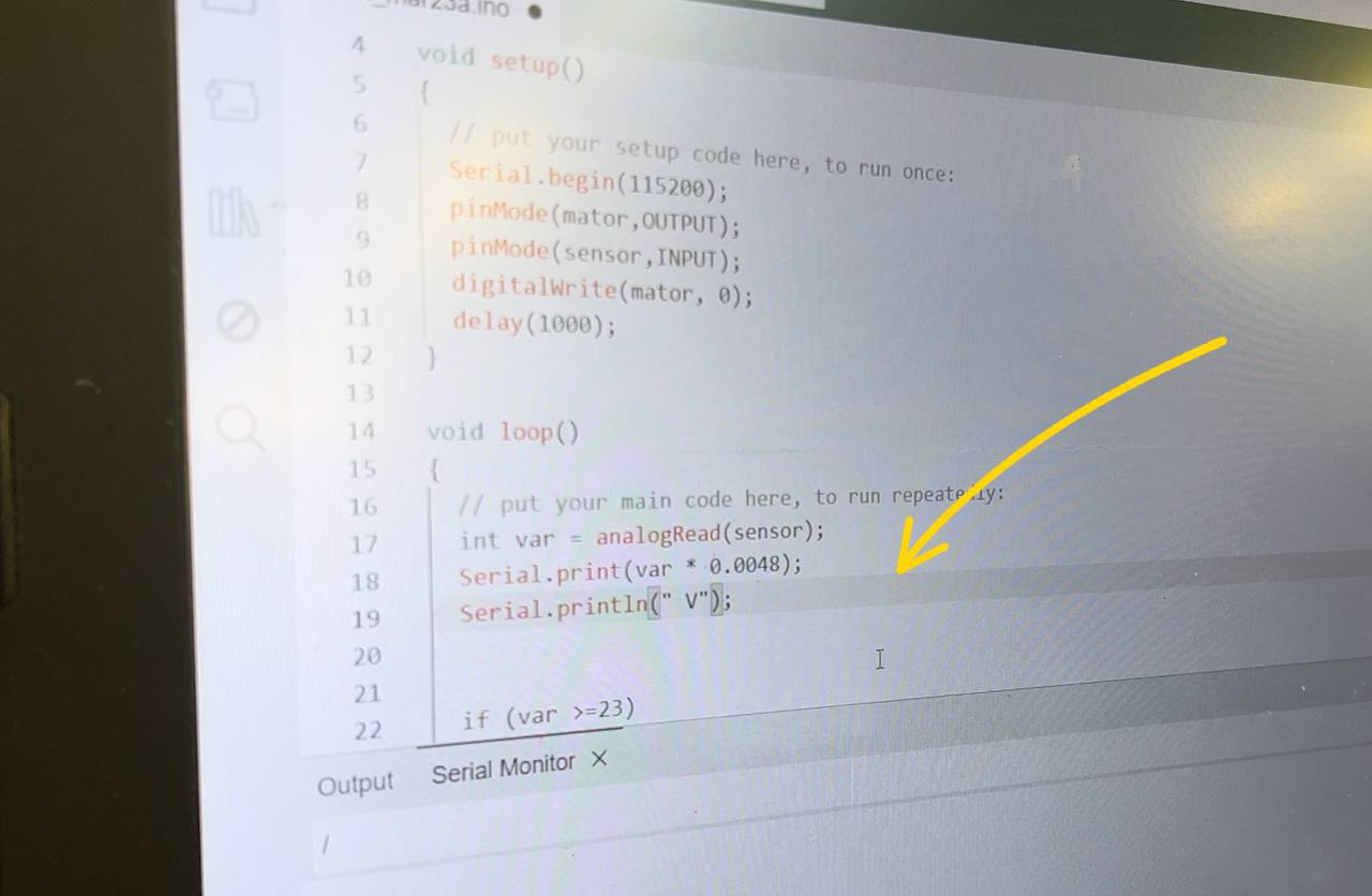
And here is the code that we wrote and worked with.
Individual Assignment
PCB Design
My PCB design sketch was ready, as I did it last week with the board in which is my microcontroller.
Remained to do the sketch in KiCad and cut it by our Roland MonoFab SRM-20.
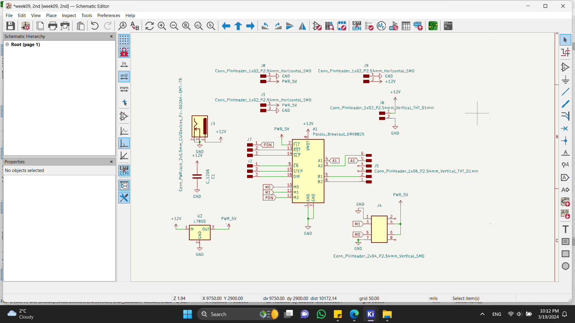
So I started from the schemes and footprints of new components(for me) - driver TMC2225, the Barrel Power jack and others.
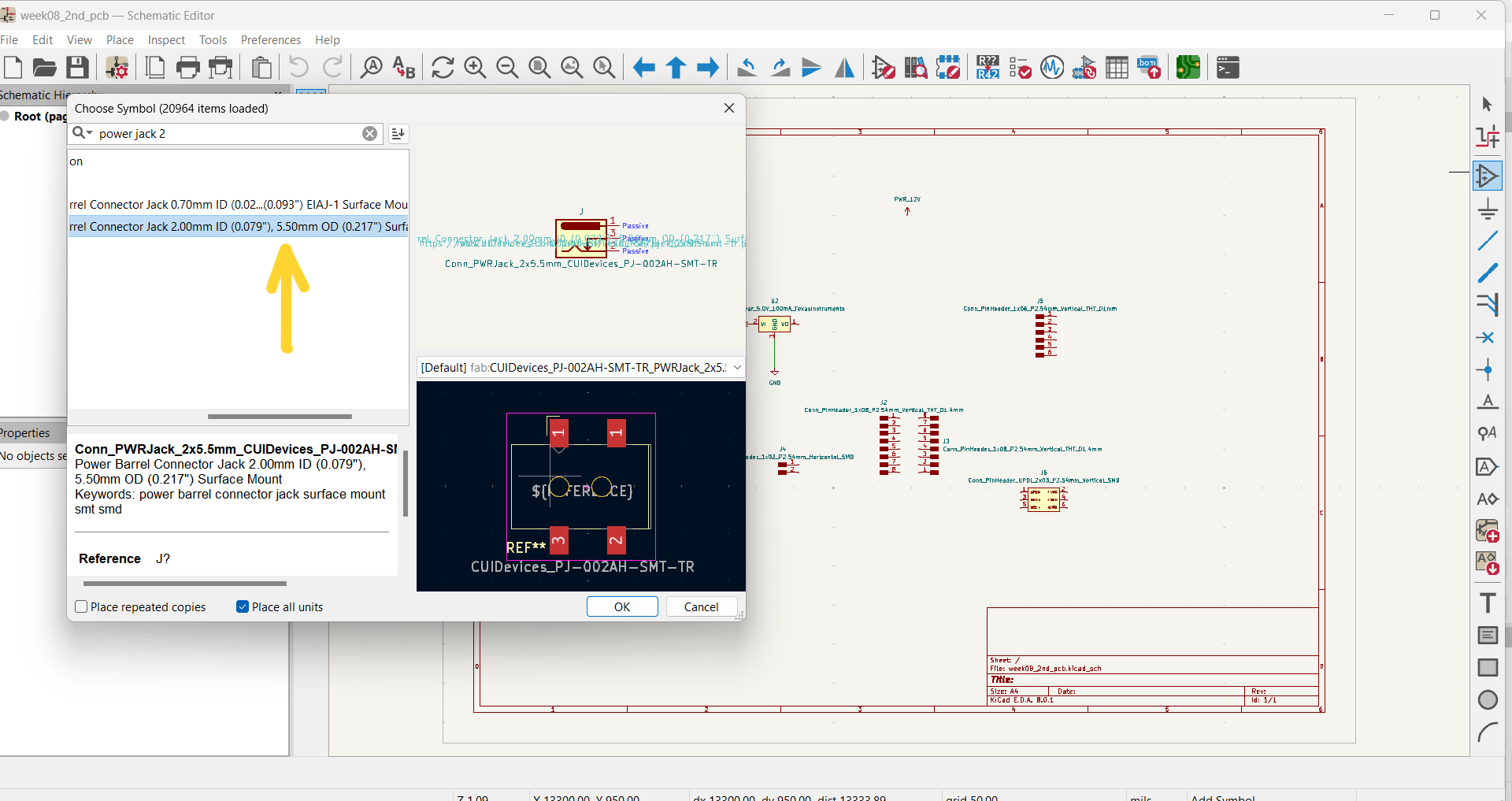
As you can see in photo, there were variants of this component, so be attentive with that to choose the right one.
This Barrel Power jack is a connection point for external power sources.
It has 2 pins - for GND and power connector. These two pins can be confusing, so be attentive with this too. In my board I designed this part on the opposite side (due to inattention), so I had to cut my board twice.
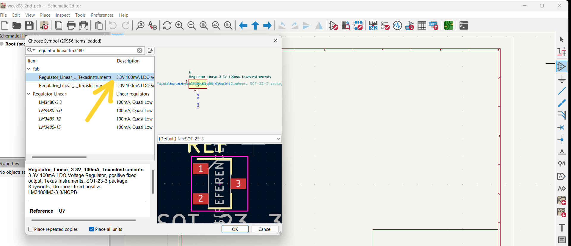
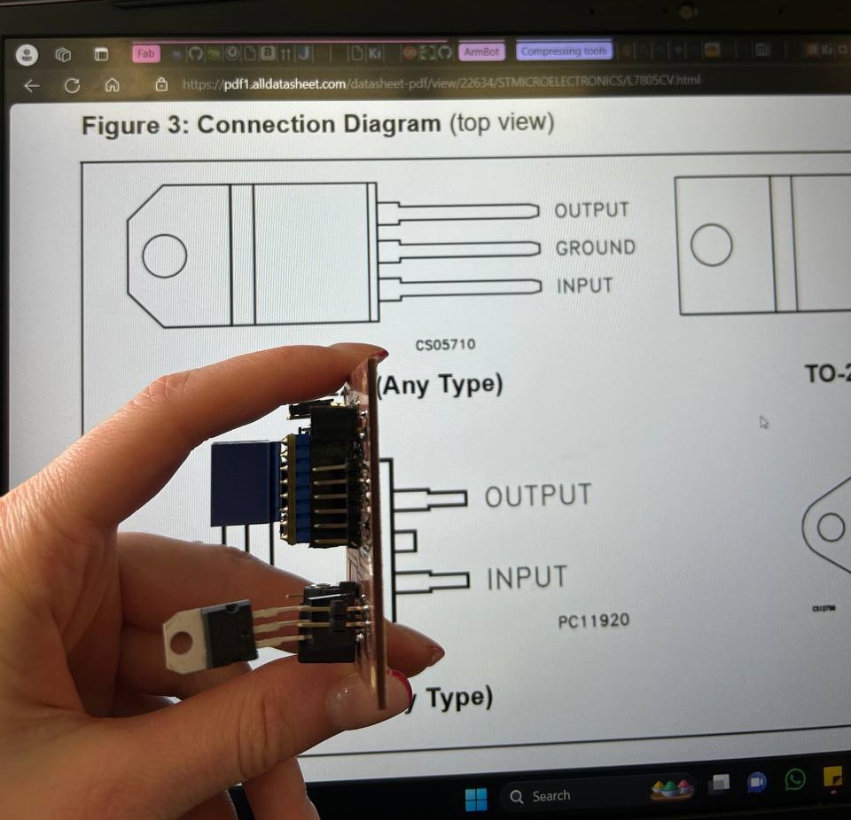
I needed 3V on my board, so for that I chose regulator that you can see in the photo below.
The TMC2225 Stepper Motor Driver’s footprint was the hardest to find. I didn’t find in my libraries and the only way was uploading it from other websites. So I found a website, in which there was this component for KiCad, but after uploading it I found out that there is no footprint on it. :(
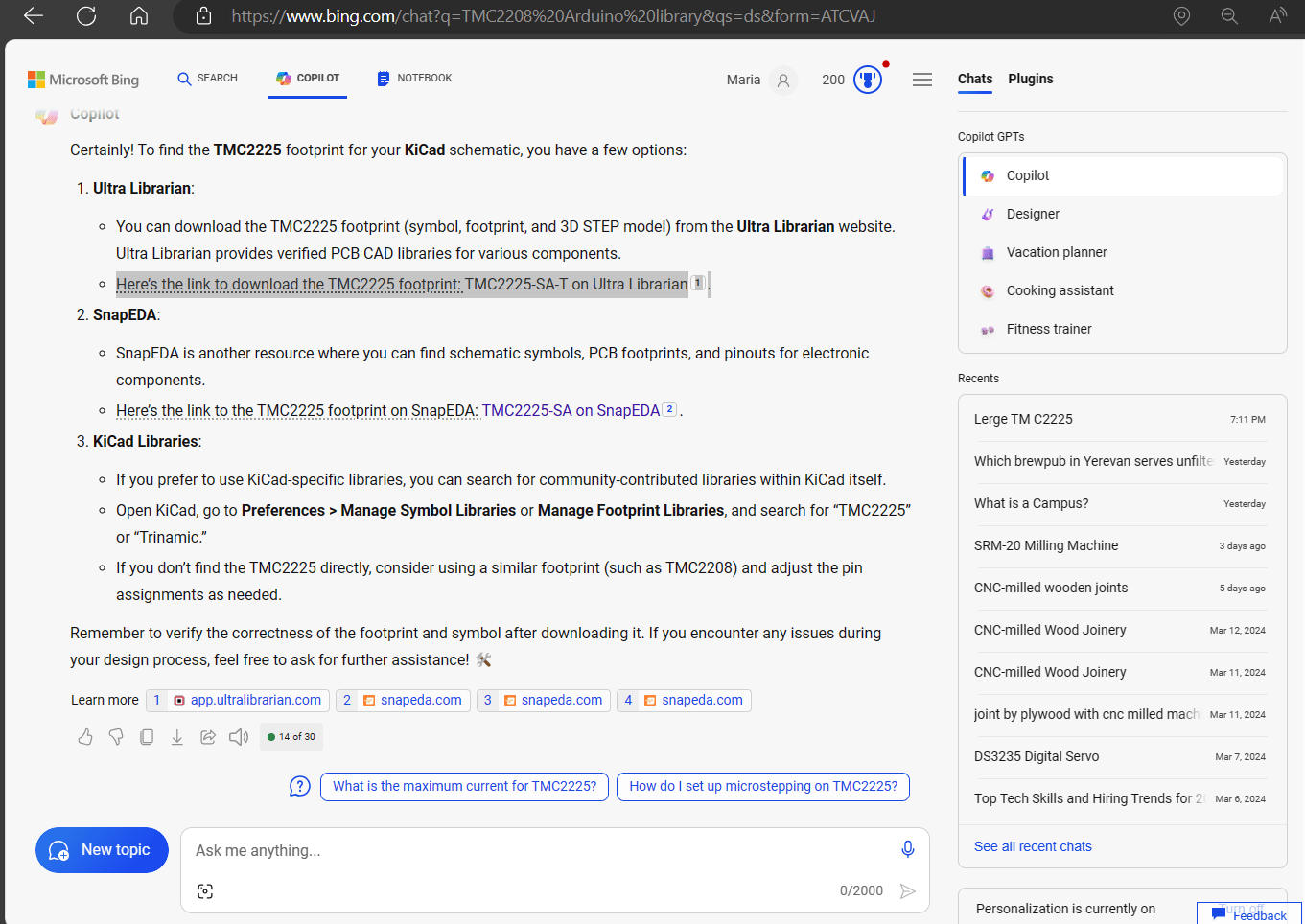
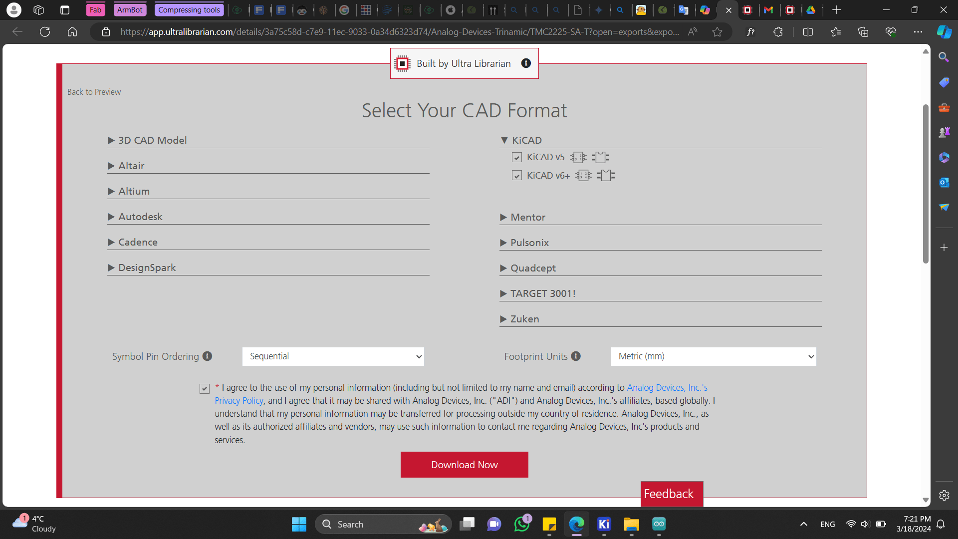
So here is the websites, were you can find useful libraries. But I didn’t find there no working footprint for TMC2225.
As I ran into this problem, one of our instructors suggested me to use TMC2208’s footprint as these 2 drivers are very similar. I just changed some pins locations, cause there were some difference between these 2 drivers.
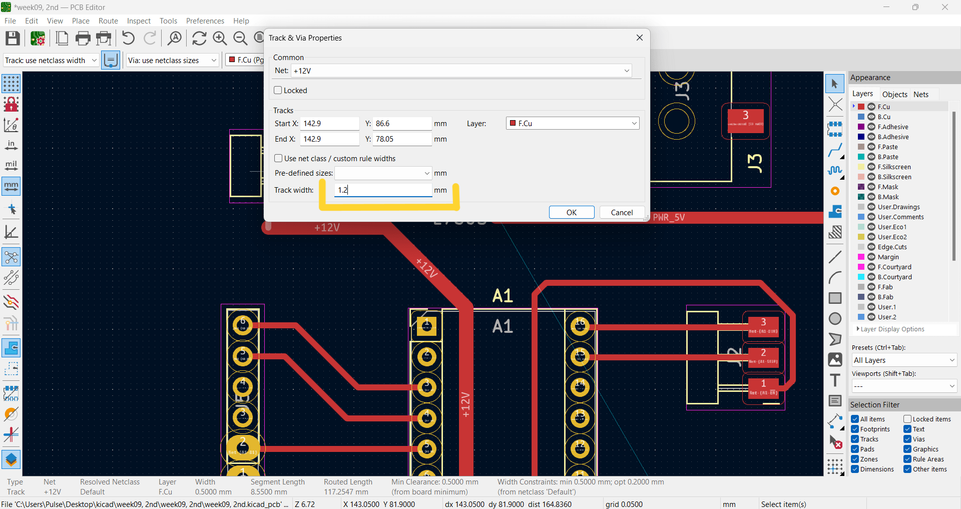
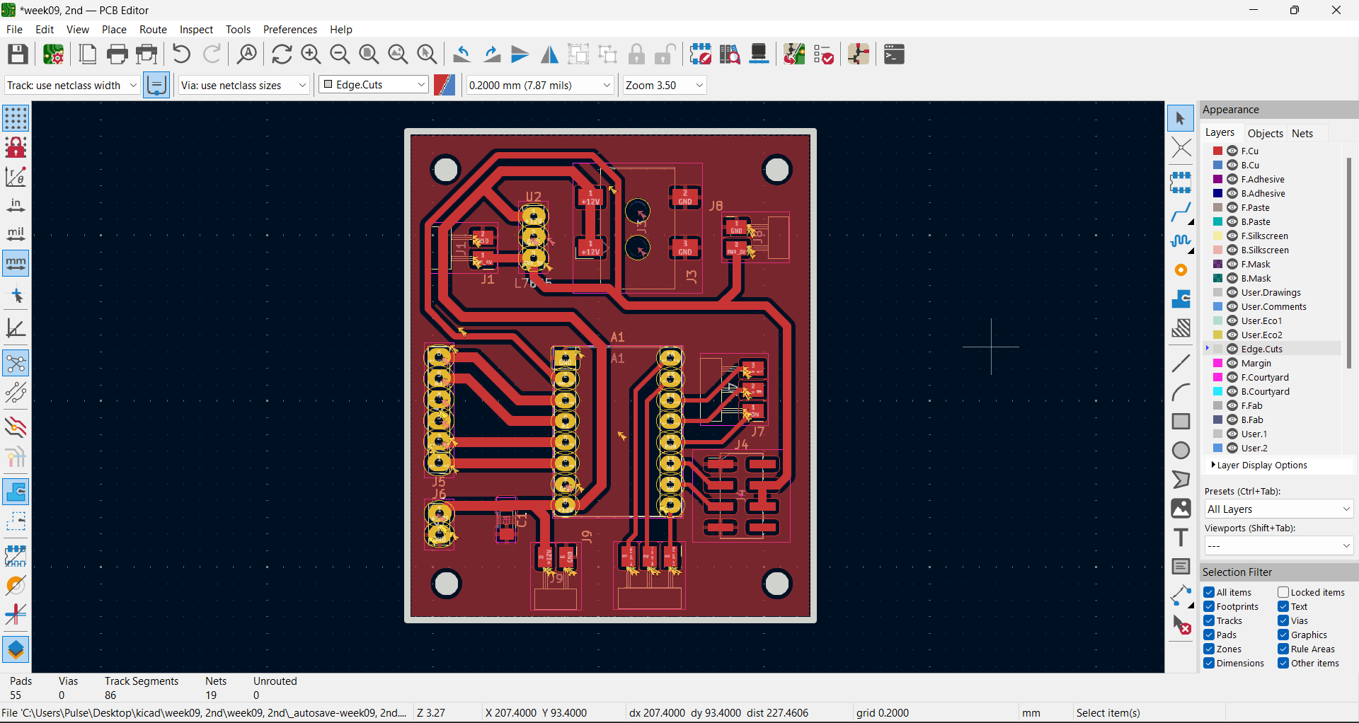
Also make sure that tracks width in your design are wide enough. For that I made them 1.2mm.
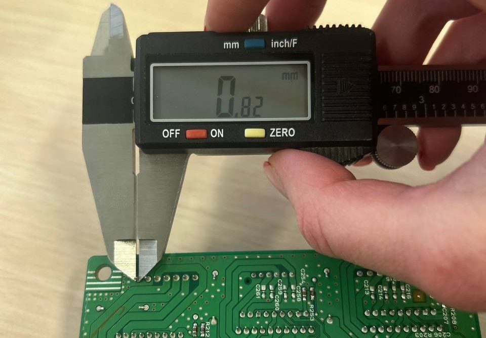
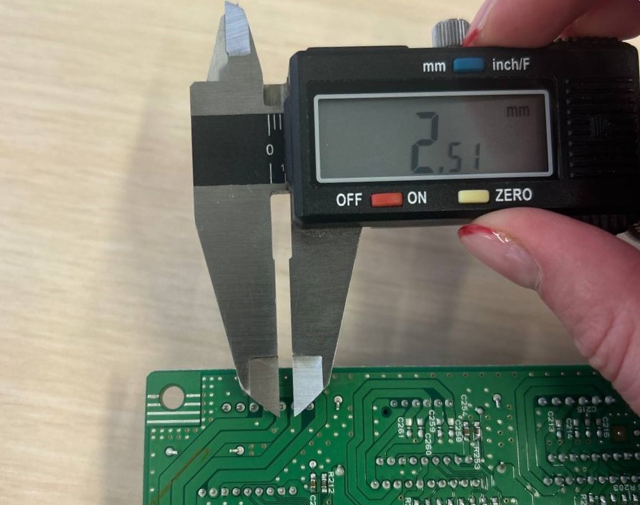
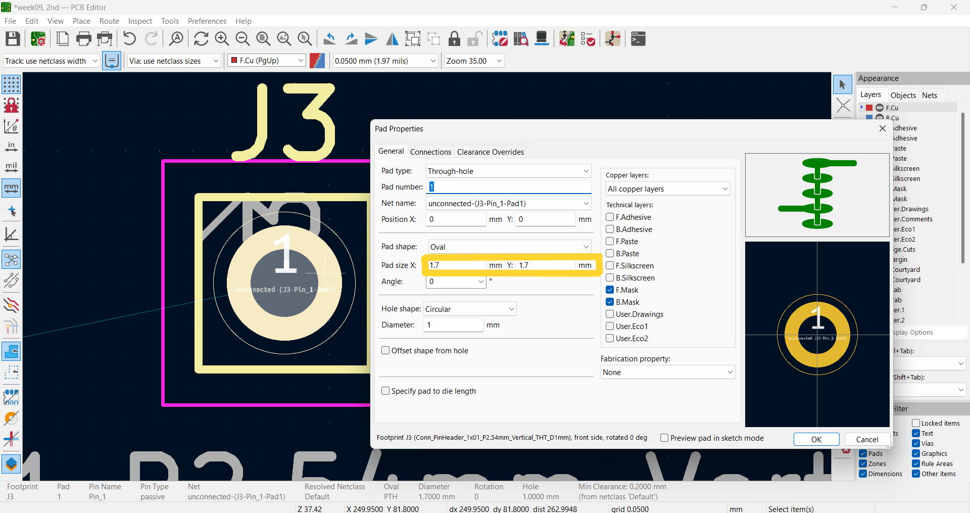
Besides that holes that had to be made for connectors soldering has been changed in sizes. In photo below you can see that there were rounded and I made them wider.
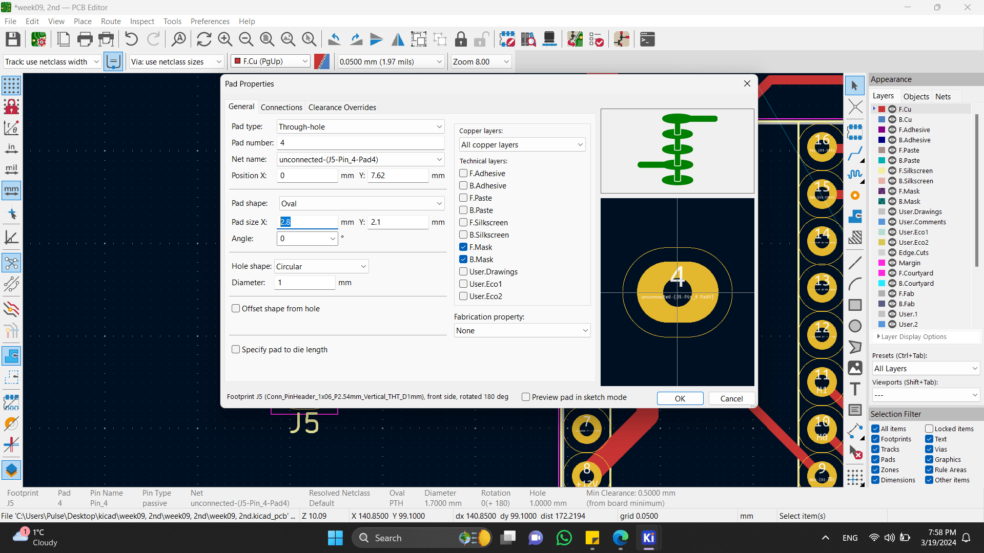
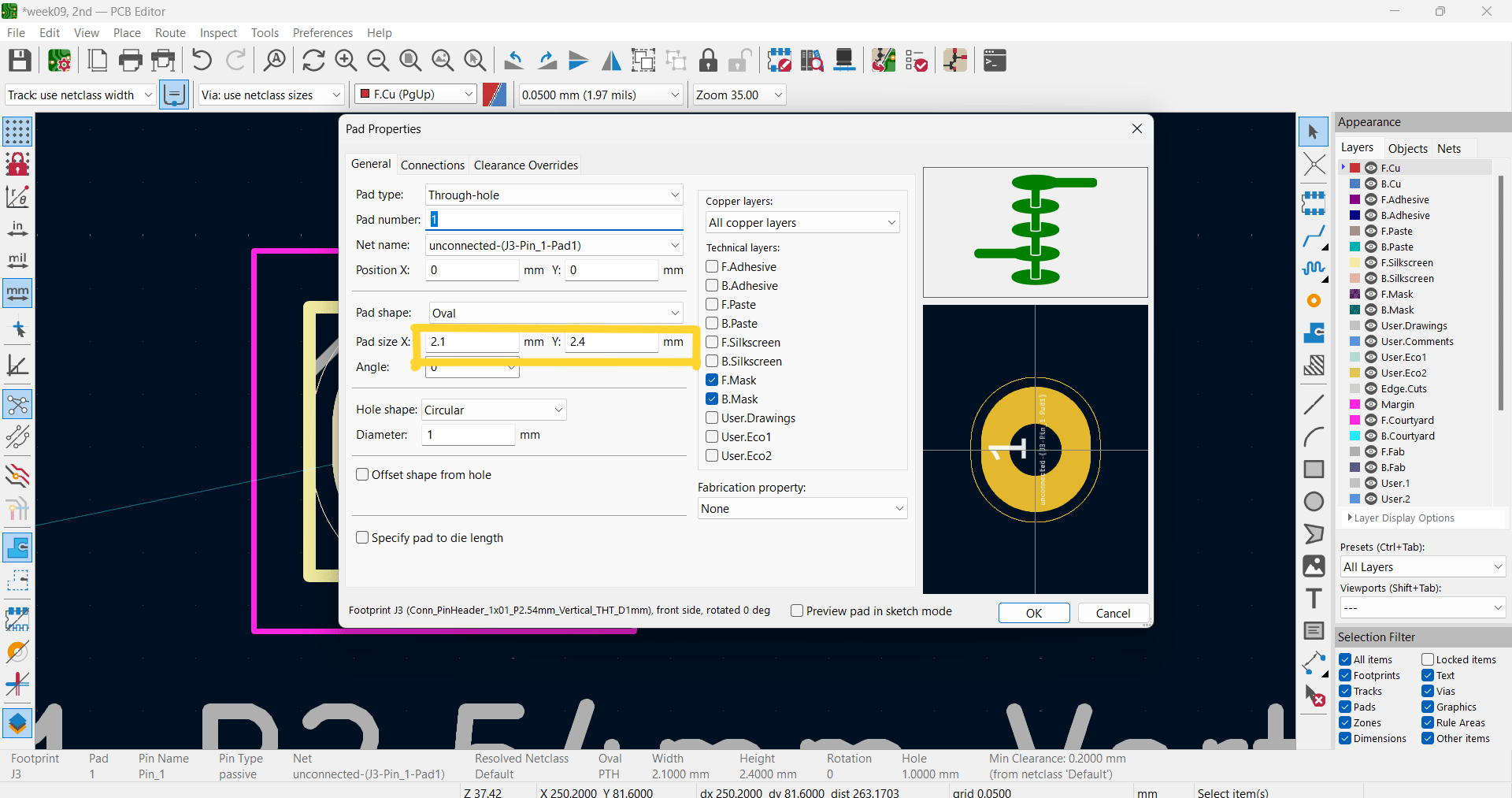
I set the minimal distance, so that it could be cut.
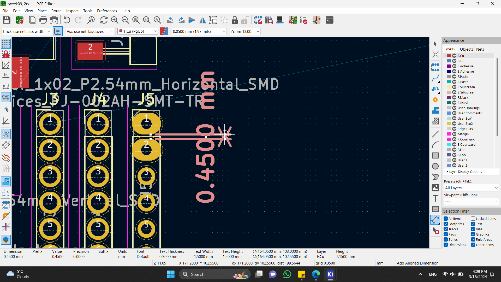
Also I changed other footprints sizes too. They were too small for our 0.4mm diameter End Mill.
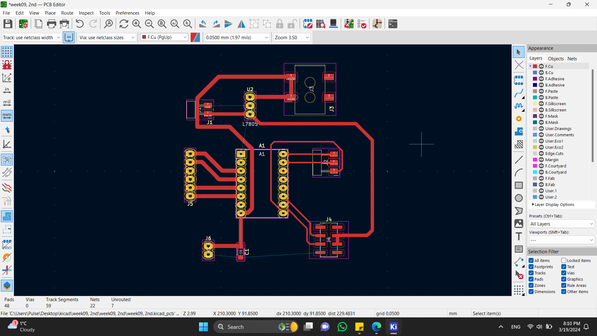
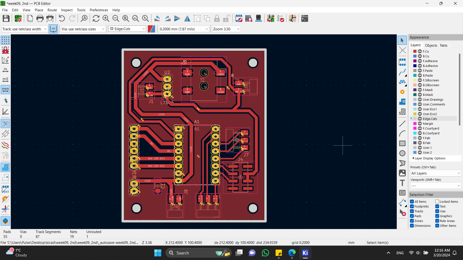
After, in PCB Design section I tried to connect my components, to have a look on it.
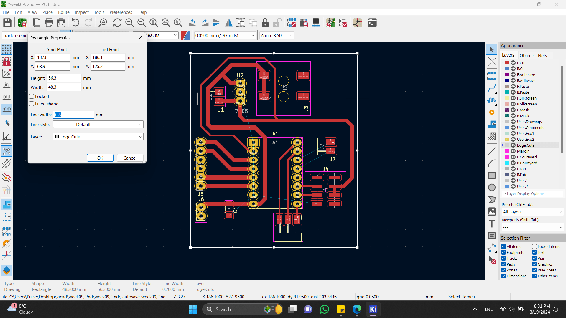
Also I fixed sizes of my PCB Board. By clicking on rectangle you can see it’s sizes and other options.
After I made holes, so that I could put and fix my PCB to my chandelier.
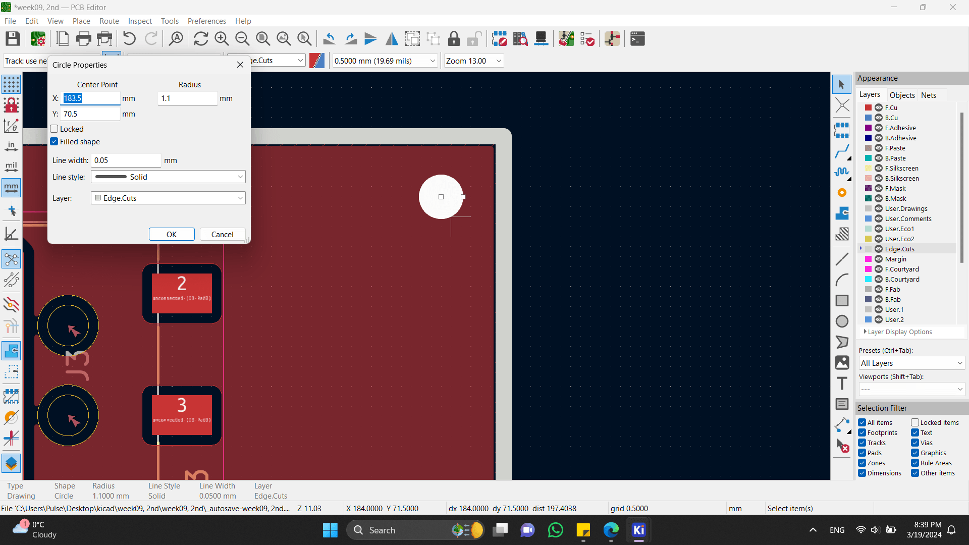
Here are sizes.
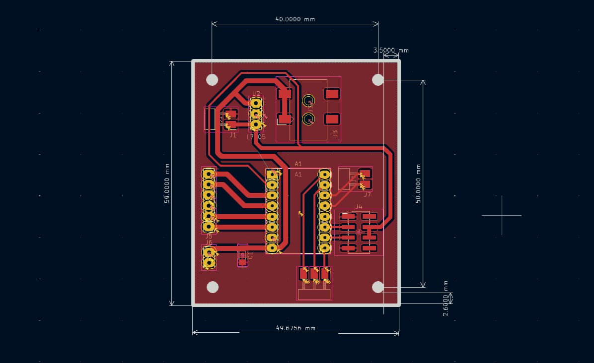
And this is the final version of my PCB Board.
Board cutting
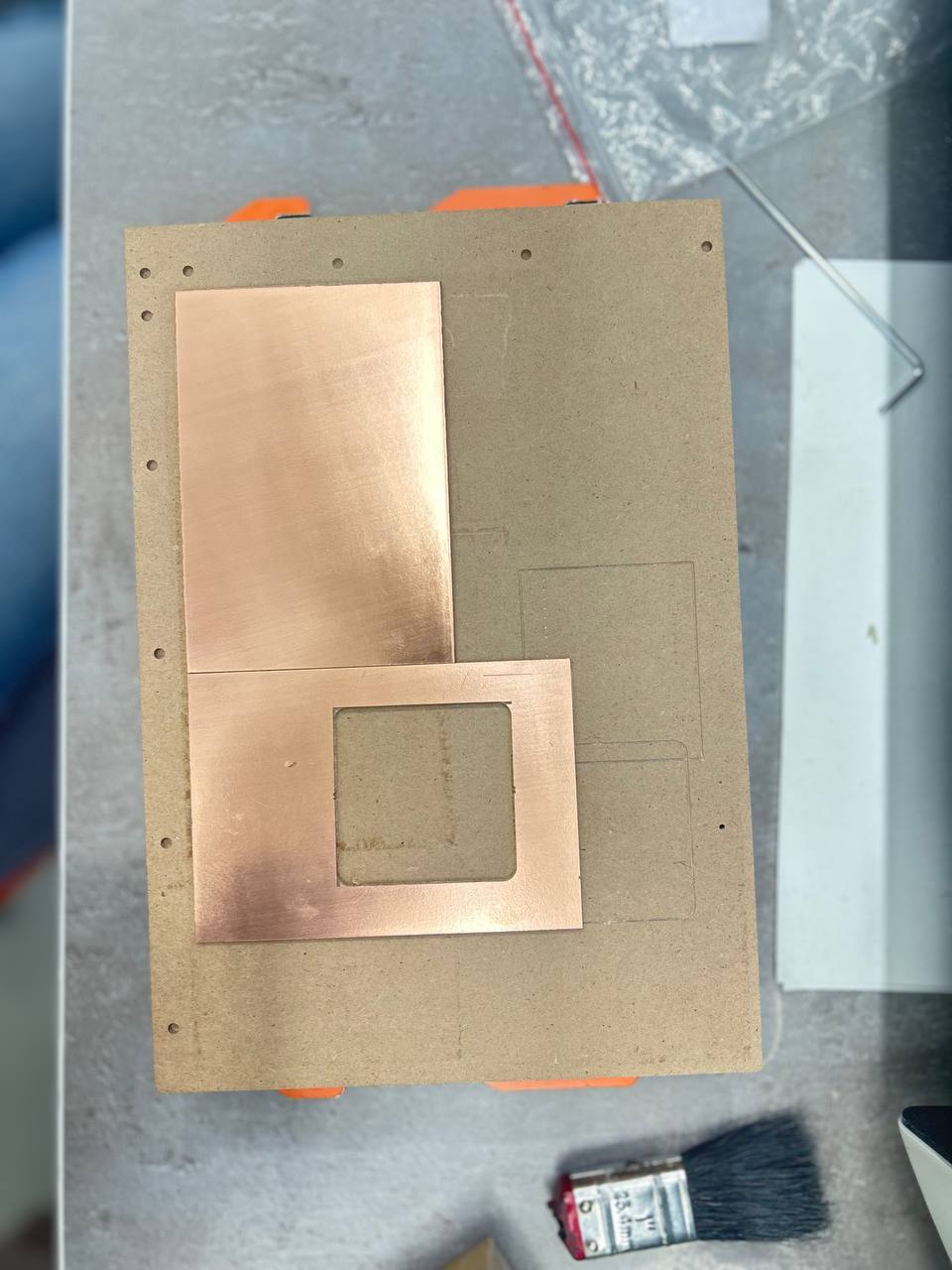
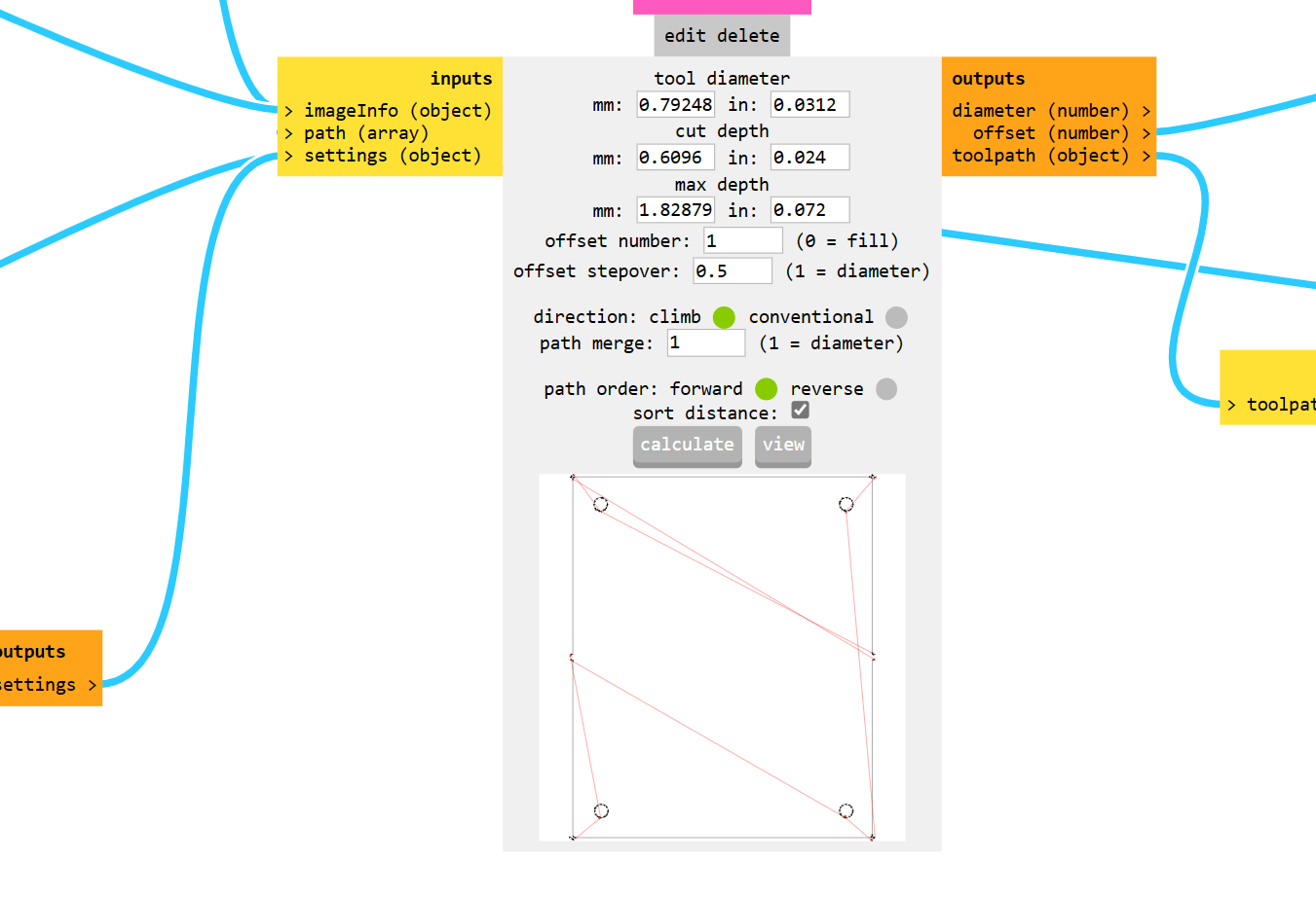
Me and Elen had PCB’s to cut, so we decided to cut it both together. And for that after generating G-Code Elen changed her board’s G54 to G58.
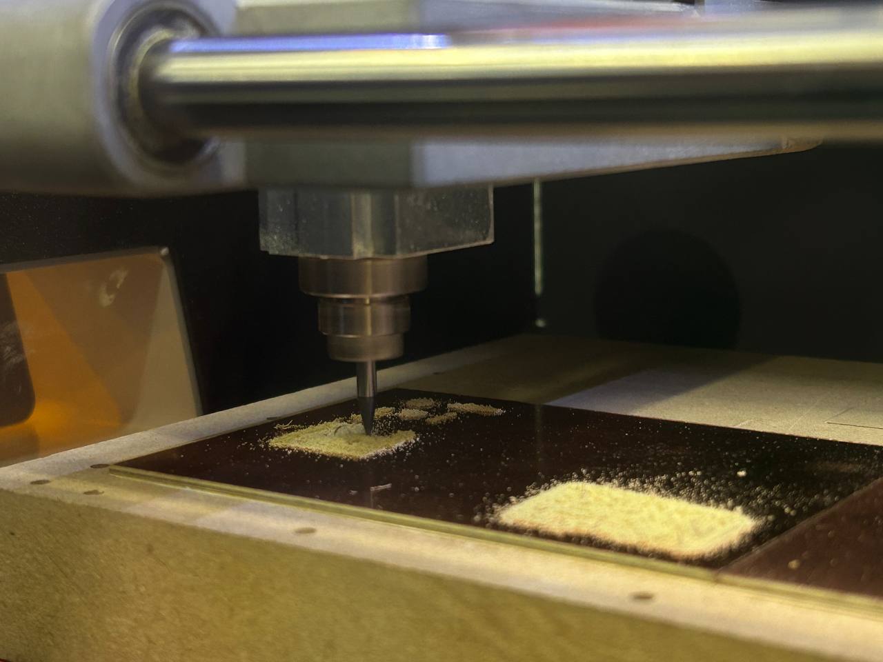
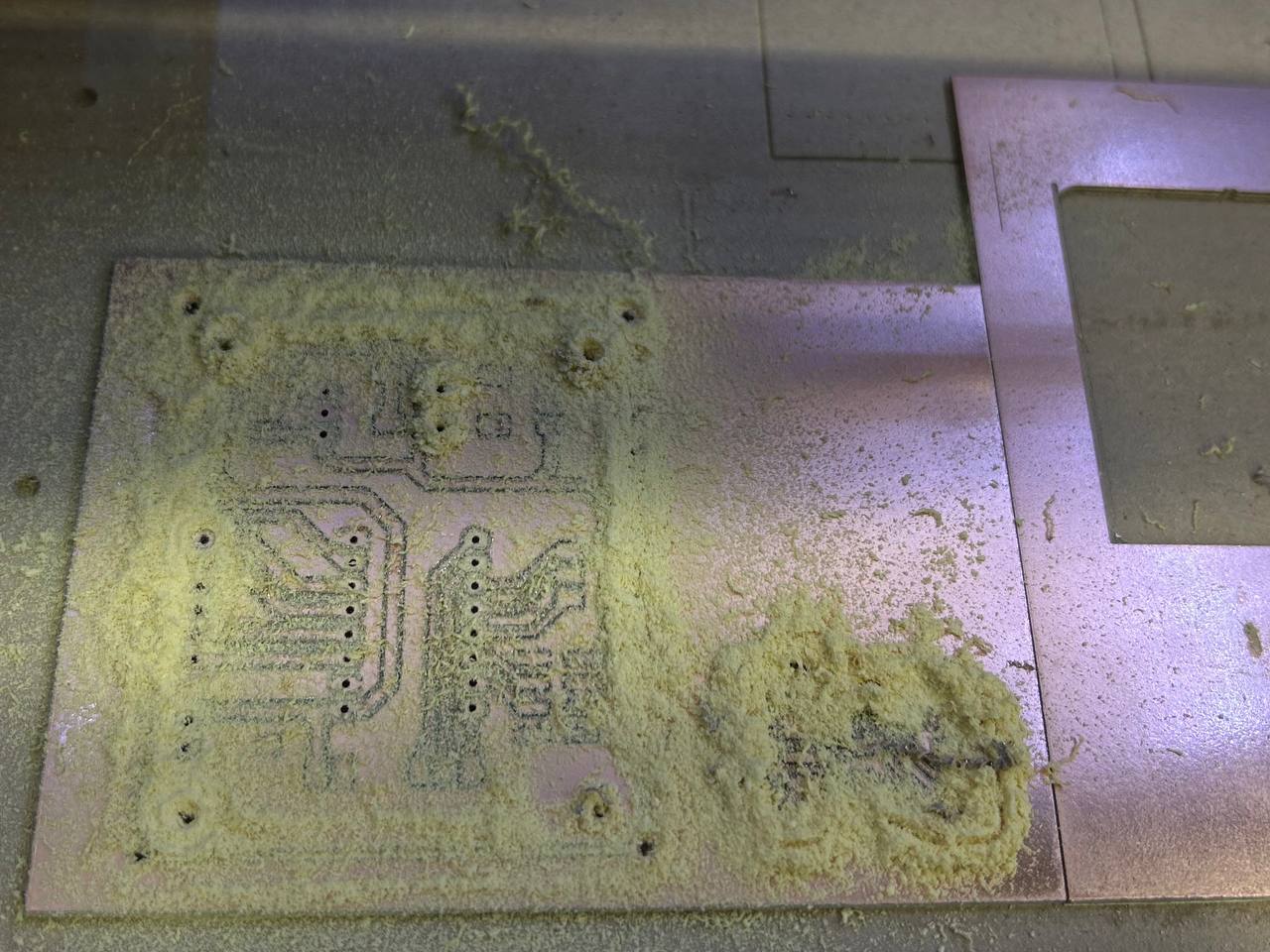
Here we got that.
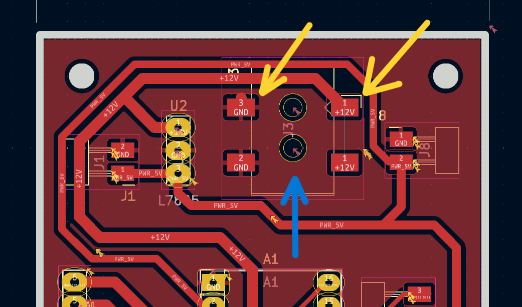
When I cut my PCB I noticed, that the Barrel Power jack footprint is in the opposite direction (Gnd and Pwr).
I changed it’s position and had to cut it twice.
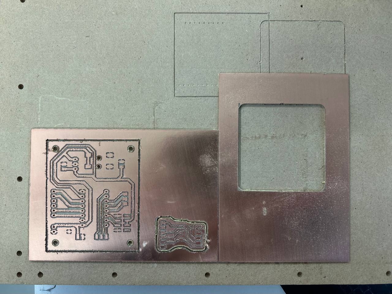
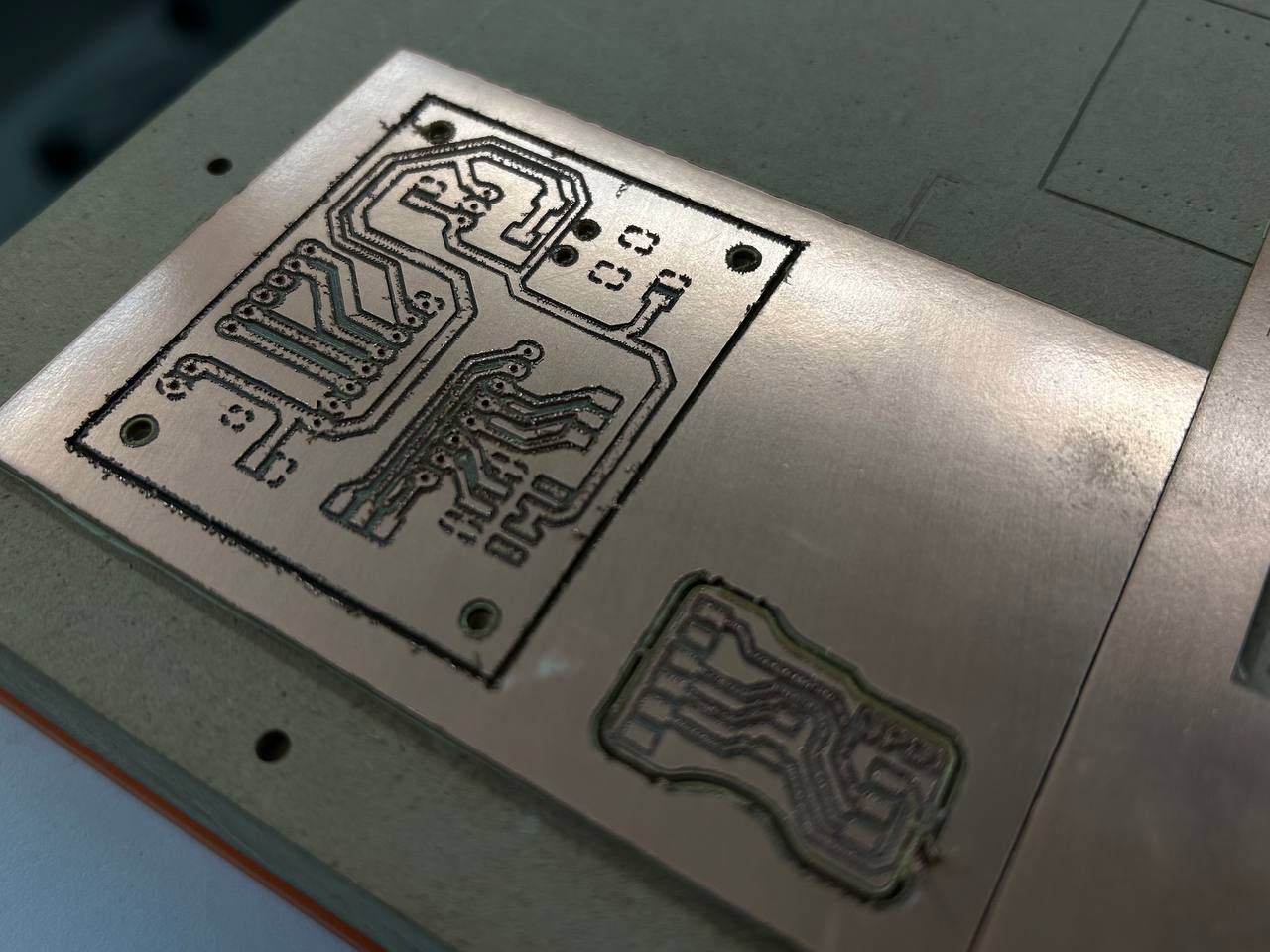
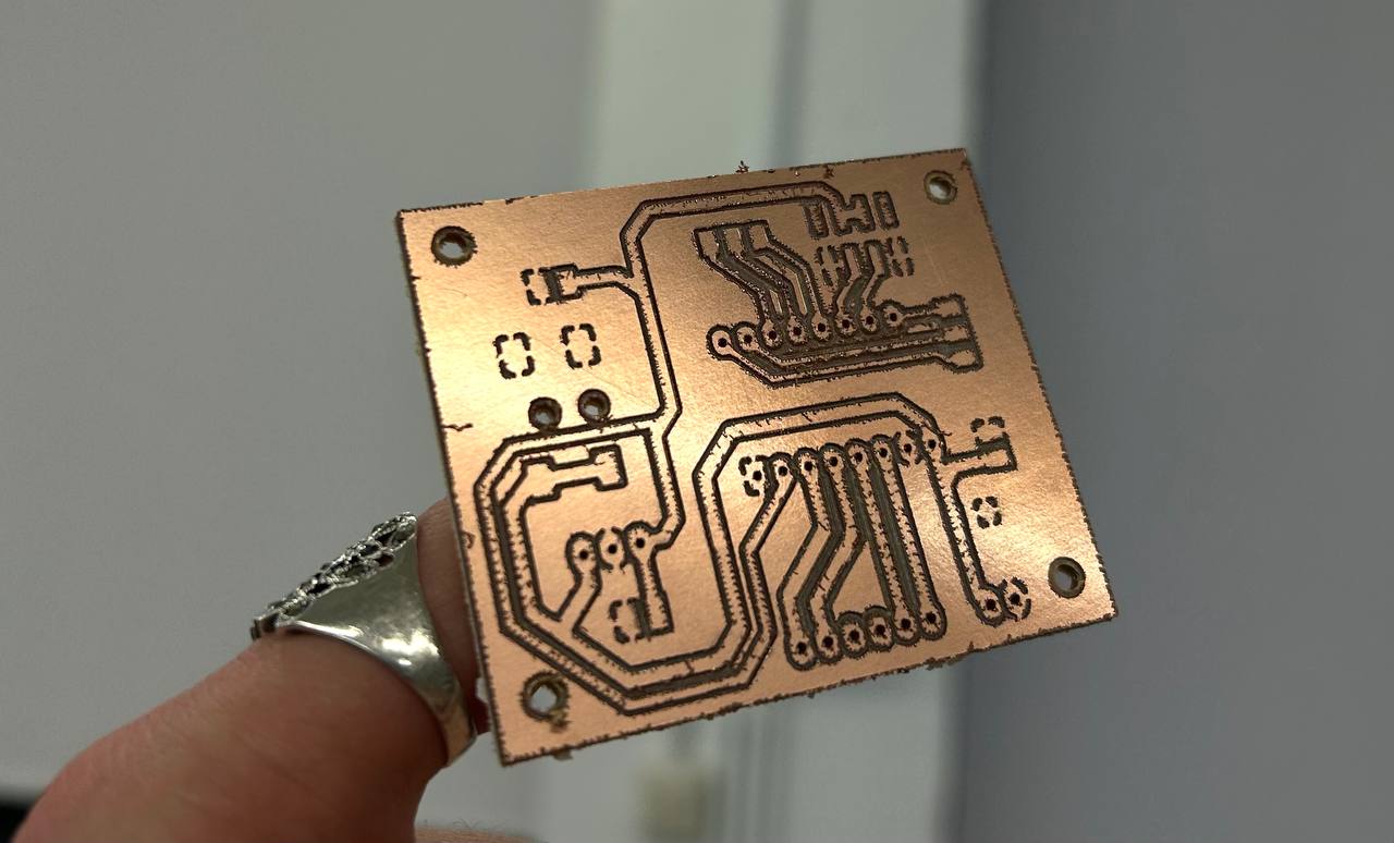
This is the final version of my second PCB.
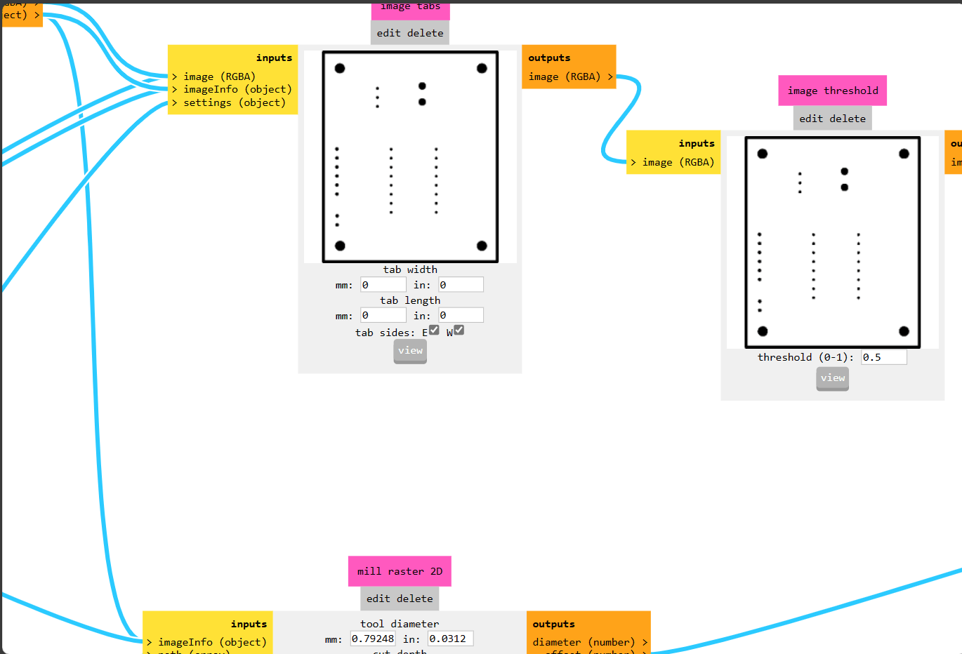
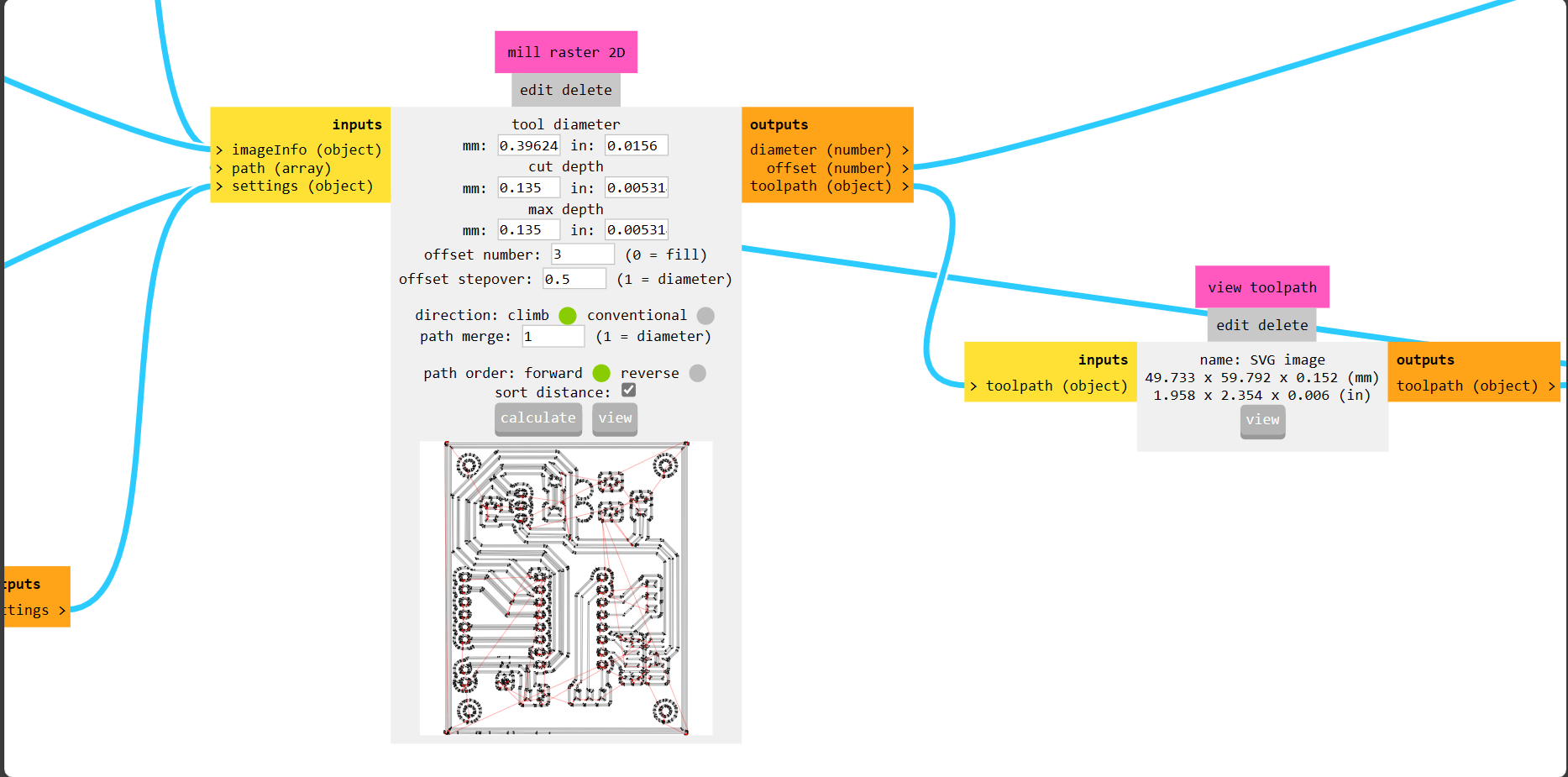

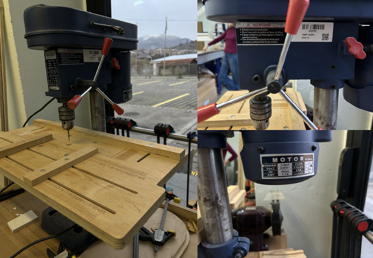
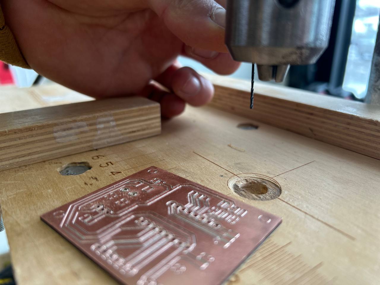
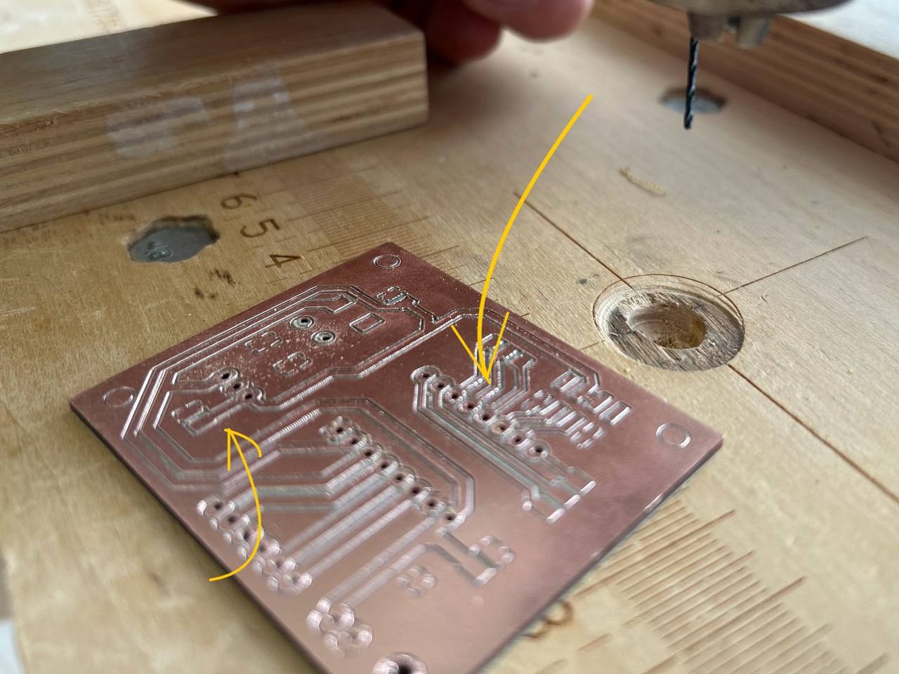
The last PCB that I cut out was correct, however after doing engraving stage, holes were not done due to G-code that was programmed to cut the outline first. The cut for holes and outline were included in the same code due to which the machine wasn’t able to cut the holes. It happened because PCB board broke out from it’s base (bed). After which the board started spinning around end mill and in that situation I could only turn off the machine.
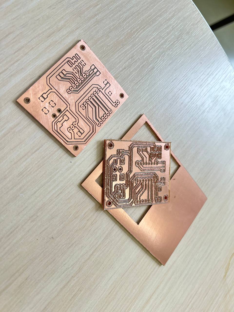
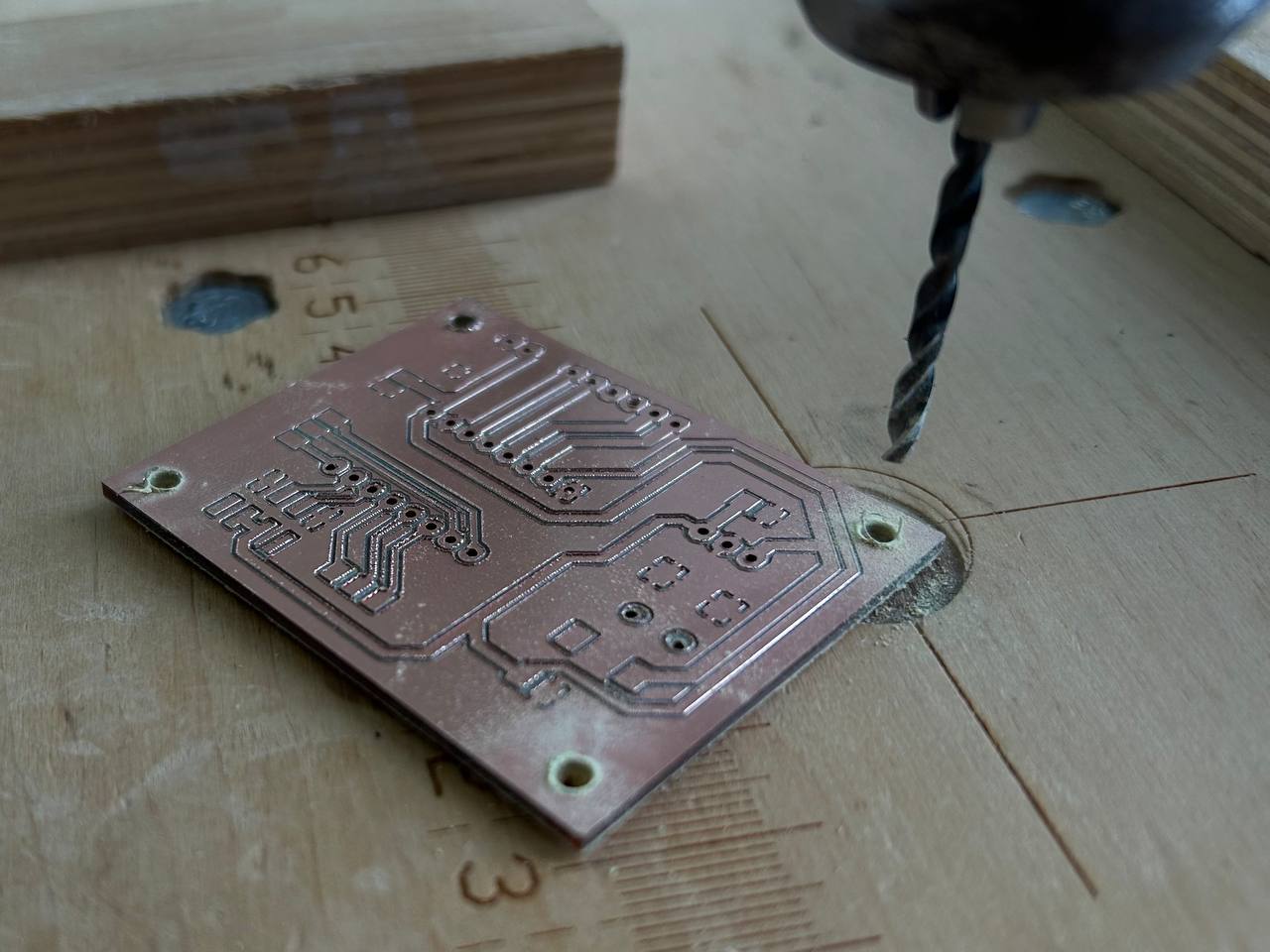
So after I could only cut out the holes by this vertical drilling machine.
Soldering
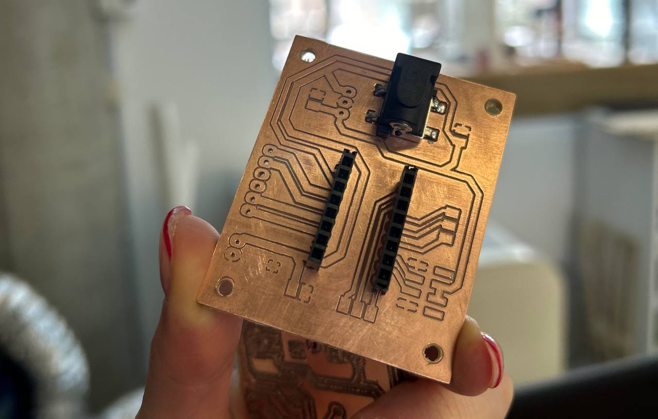
After I started soldering components. First I soldered Power jack.
As I soldered connectors for driver I had some troubles with neat soldering. Because of that pins stuck together. I tried remove solder with Solder braid. Solder braid is a desoldering tool used to remove solder when re-working the solder.
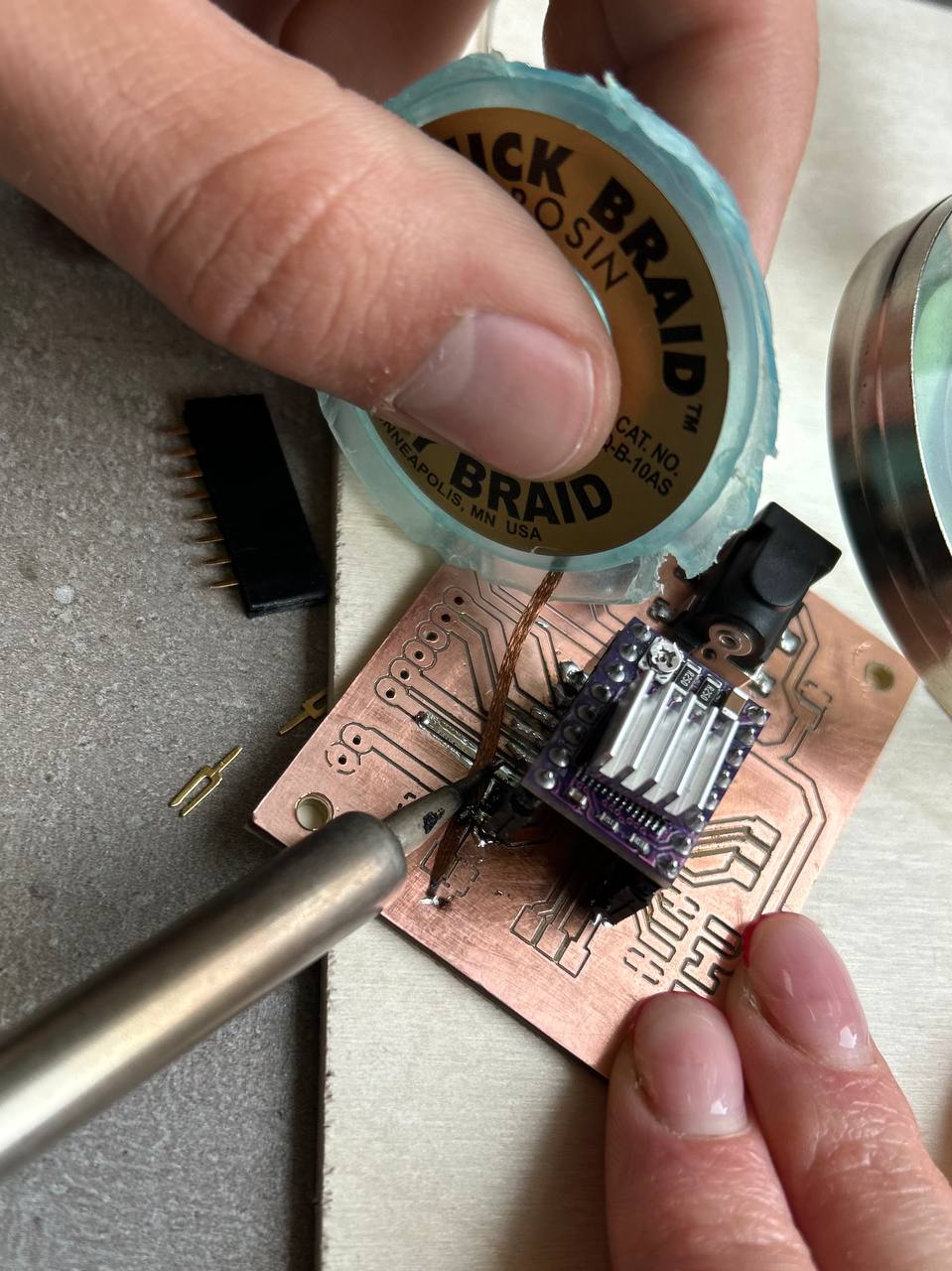
So the only way was to make lines like in the photo below.
Continuing until connector’s footprints.
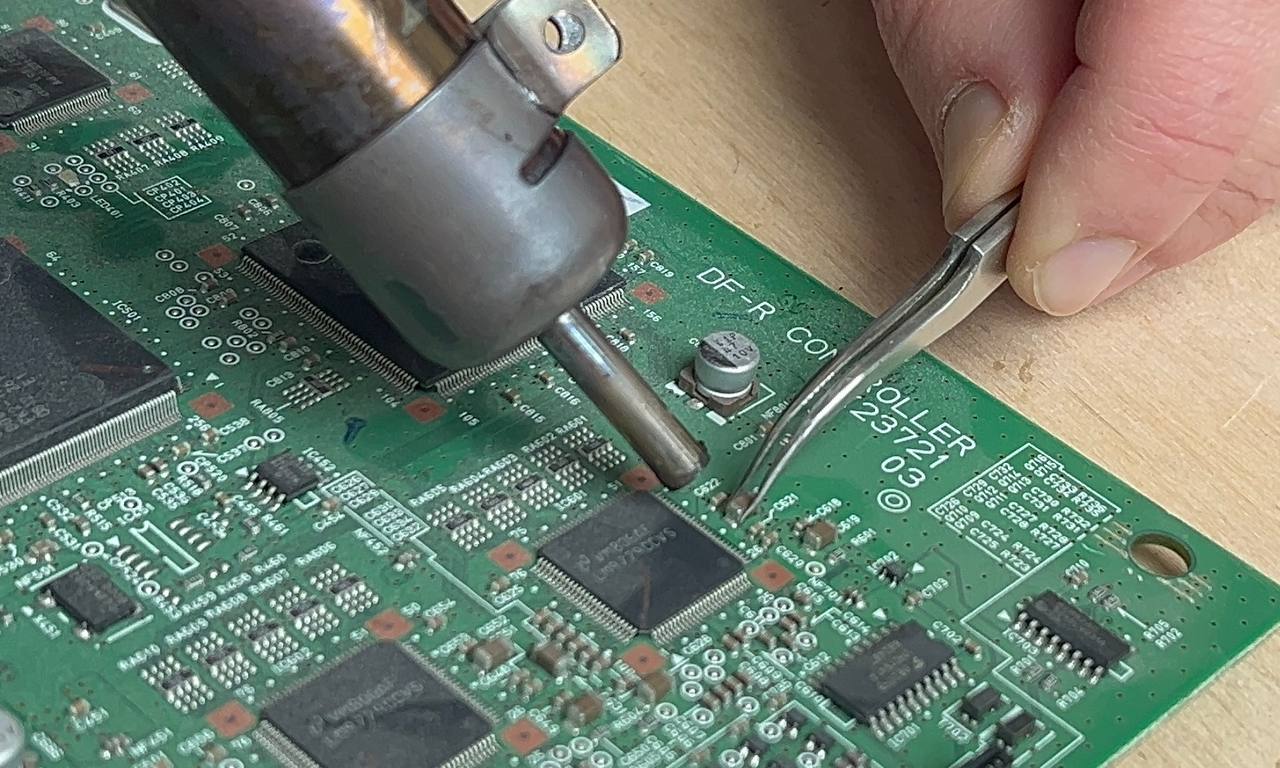
I needed a capacitor which was not in our FabLab in that moment, so my instructor suggested to extract from other PCB boards that are not usable anymore.
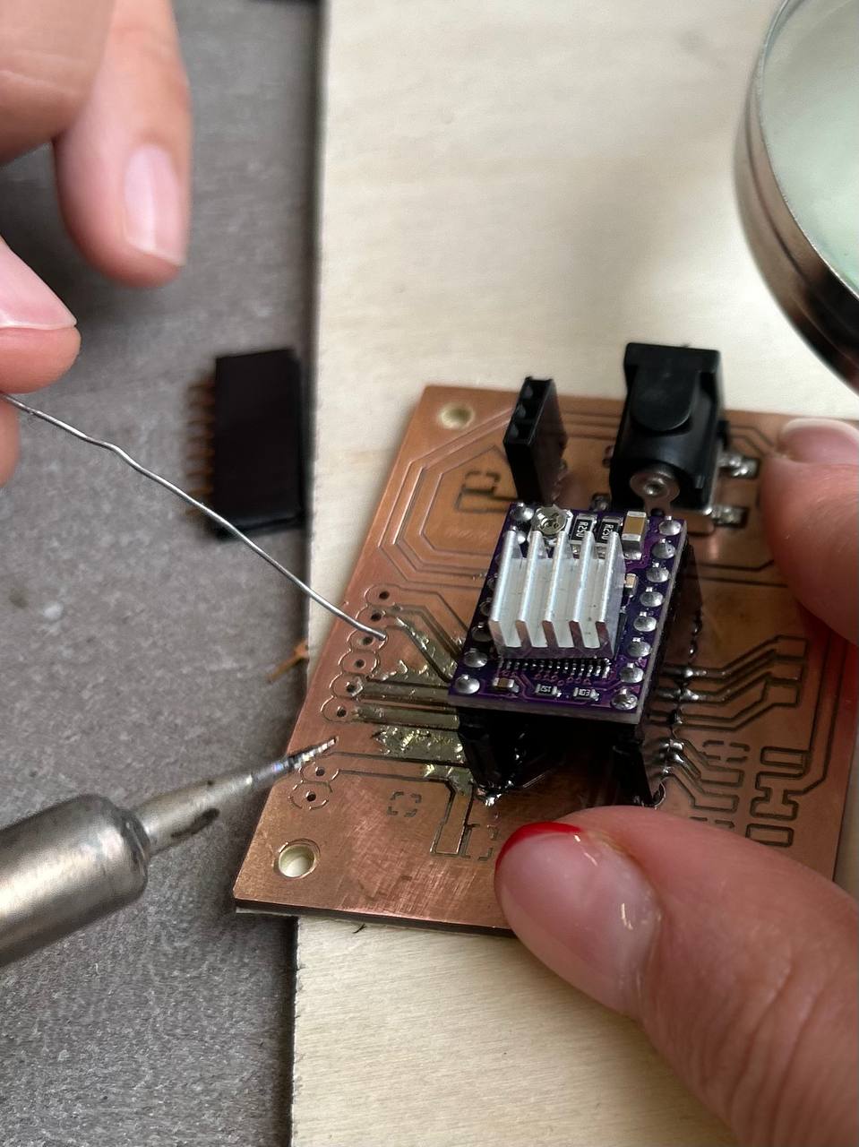
After I did connectors and other small components soldering I had another challenging soldering process.
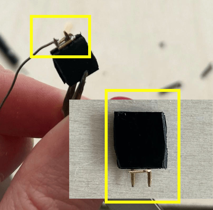
This component I made for the microstepping mode for the stepper motor. Microstepping allows improved control over the motor’s position by dividing each full step into smaller steps.
In full stepping, the motor moves from one full step to the next. If your stepper motor has 200 full steps per revolution (1.8 degrees per step), then one full step accords to 1.8 degrees of rotation.
Microstepping further subdivides each full step into smaller increments. For example: - In 1/2 microstepping, each full step is divided into two smaller steps (half steps). - In 1/4 microstepping, each full step is divided into four smaller steps. - In 1/8 microstepping, each full step is divided into eight smaller steps.
I could’t find that jumper type, so I made it by myself.
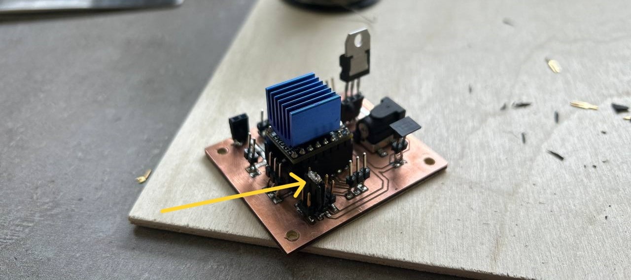
Connector slot that I soldered for Voltage Regulator to put in it, was not soldered well.
 q
Checking voltage I couldn’t understand what’s the problem, so after I just soldered L7805cv wsa chn 2218 voltage regulator to my board.
q
Checking voltage I couldn’t understand what’s the problem, so after I just soldered L7805cv wsa chn 2218 voltage regulator to my board.
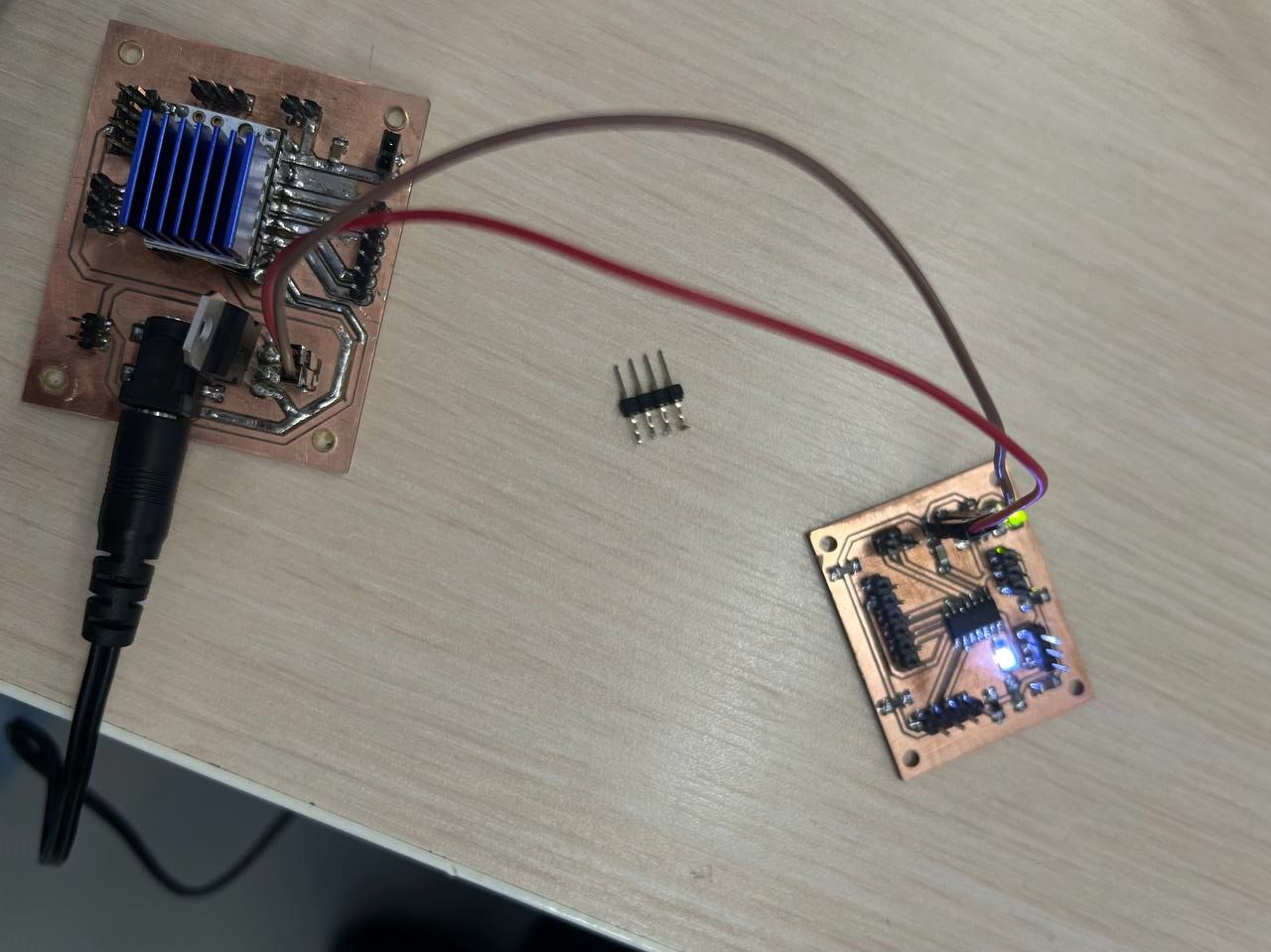
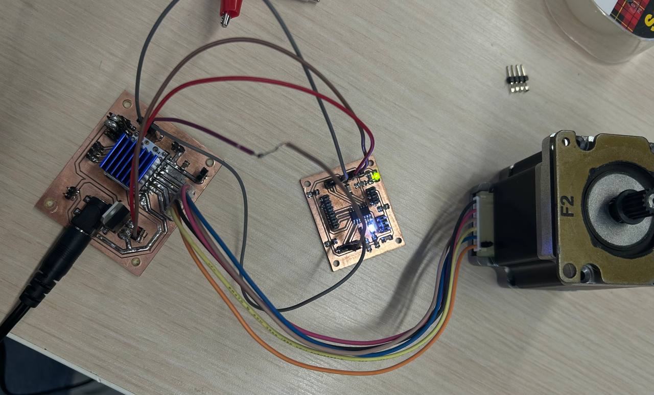
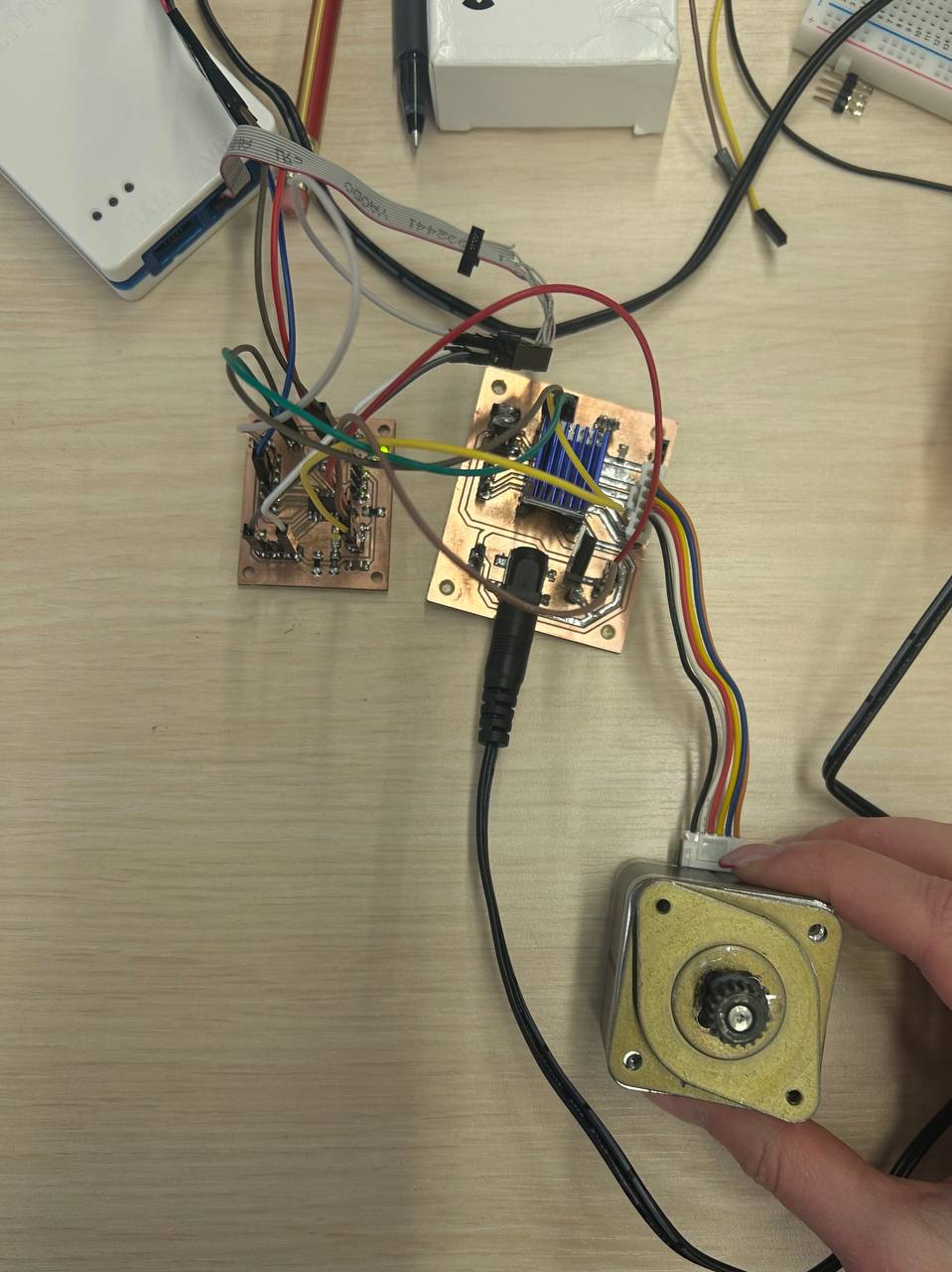
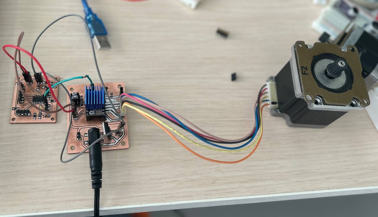
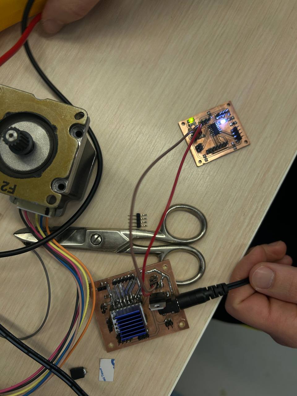
After I tried to connect boards.
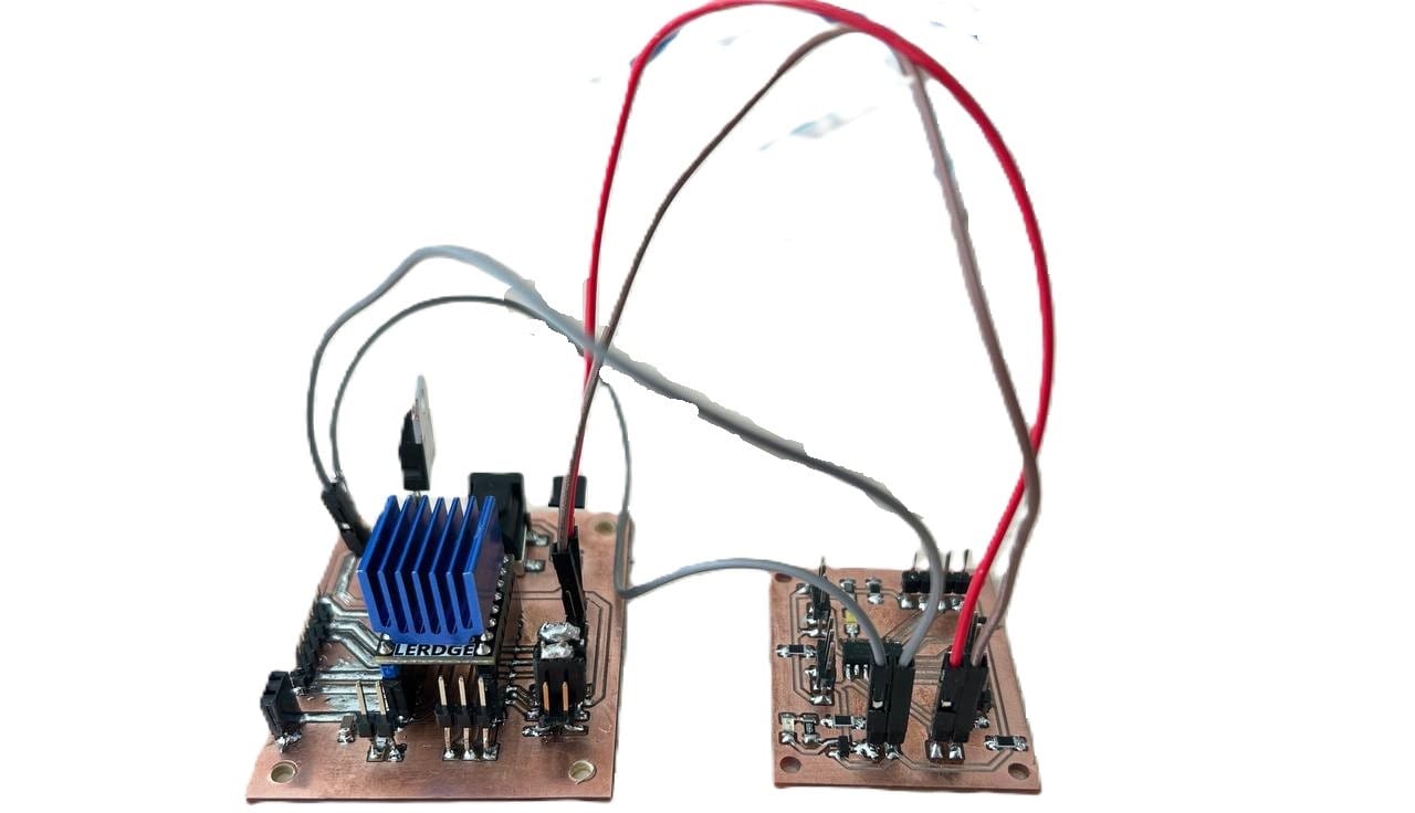
Powering primary board through driver’s board.
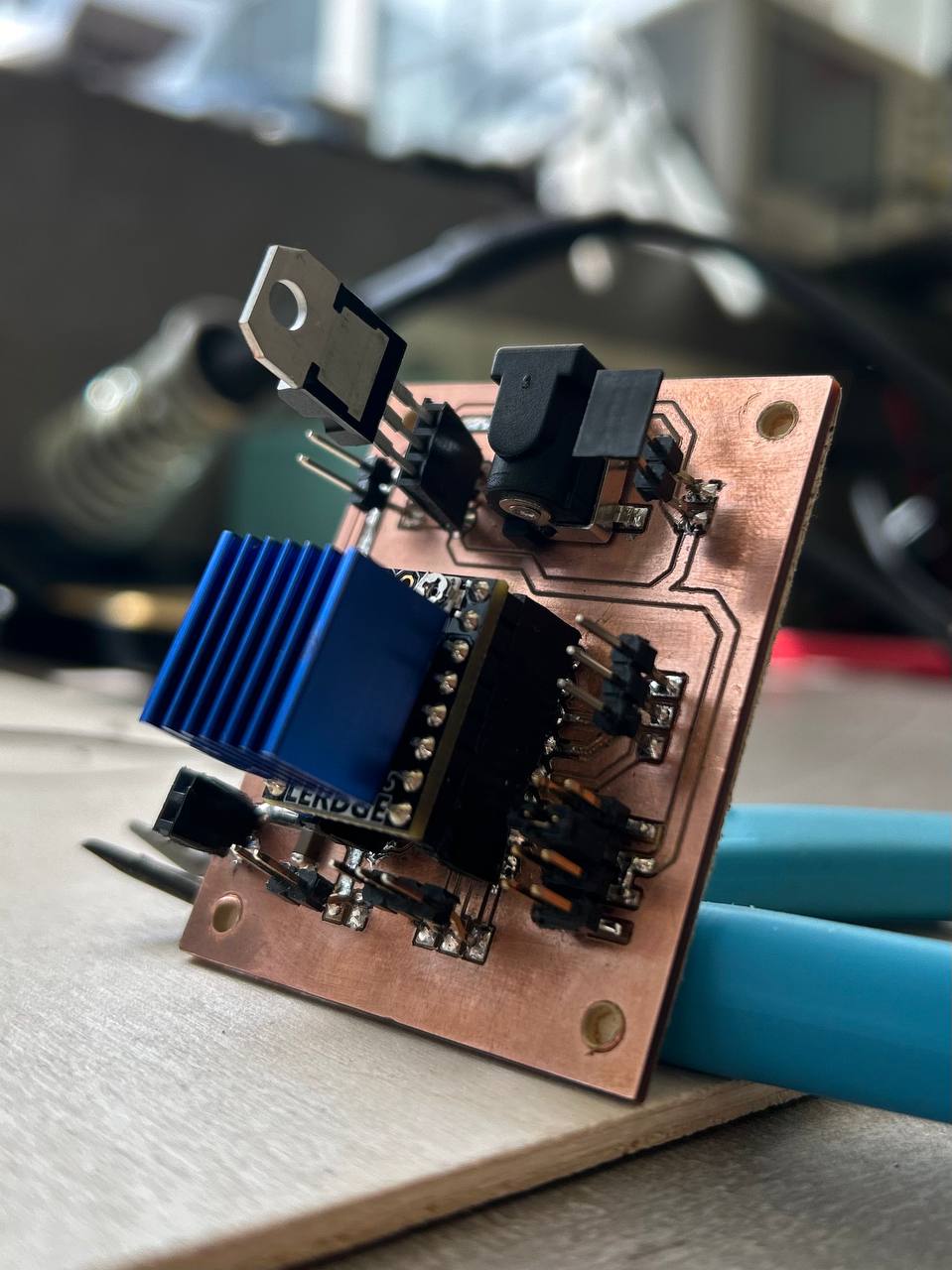
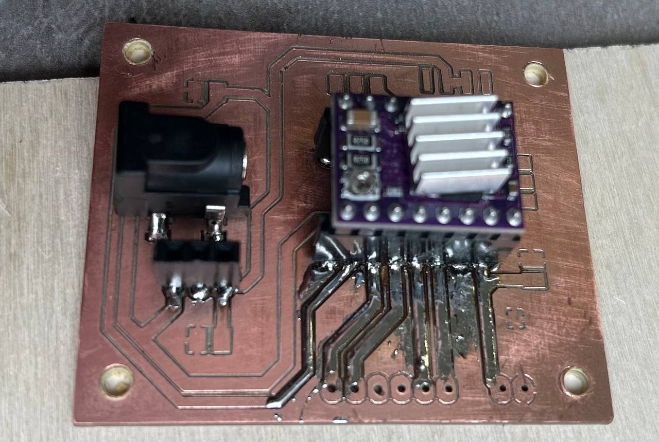
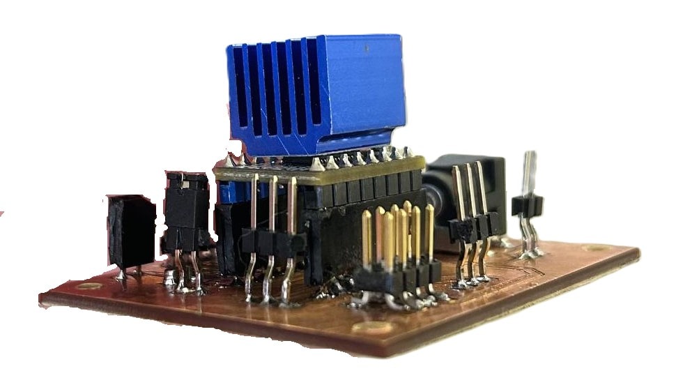
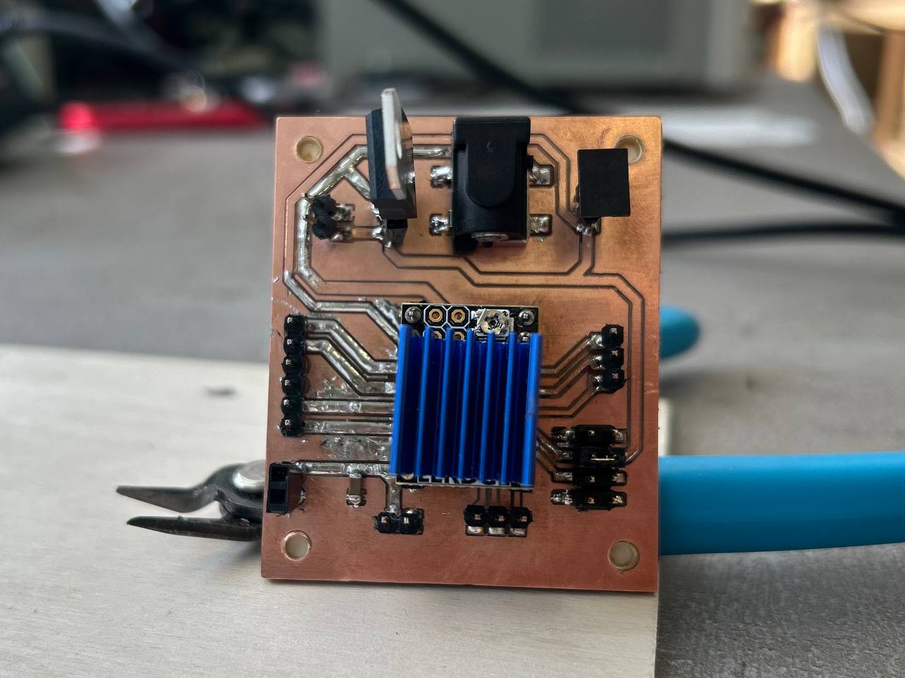
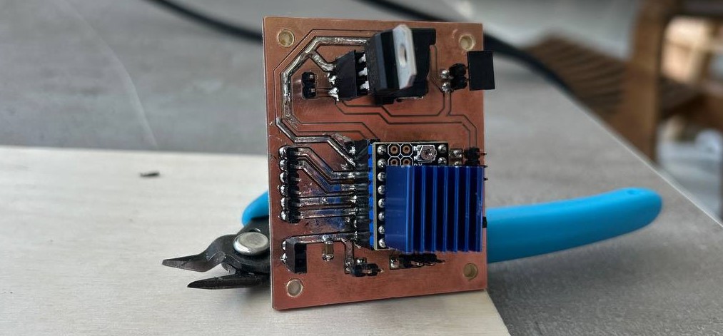
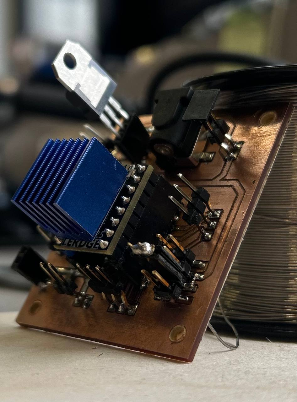
Final Shots of the board for this week.
Motor as an output device
I also look into mechanism of stepper motor and how it works. Due to drivers working way, it turn on and off rotation of stepper motor.
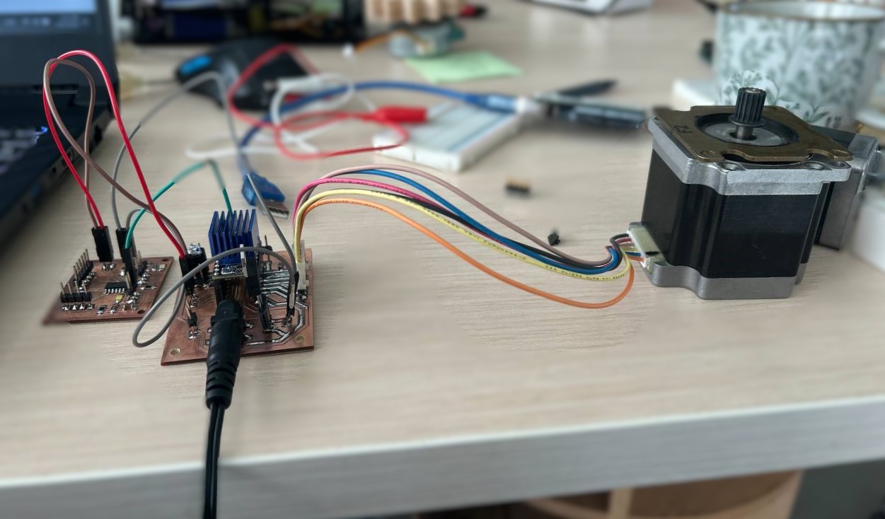
Connections of wires.
So I started writing code by Arduino IDE for this.
I created function “rps” - rotation per second.
void rps(int time = 1) {
  // Make steps (you can customize this part)
  // int time = time;
  digitalWrite(STEP_PIN, HIGH);
  delayMicroseconds(500000/2000); // Adjust delay as needed
  digitalWrite(STEP_PIN, LOW);
  delayMicroseconds(500000/2000); // Adjust delay as needed
}
By this void rps(int time = 1) { I made it so that function must accept a value of type int - named “time”.
When I write time = 1, if I don’t give any other value to it, code will accept it as 1.
I programmed my microcontroller by Atmel ICE programmer. You see more about it on my previous week’s documentation.
And the final code for stepper motor was:
#include <Arduino.h>

#define EN_PIN    4 // Enable (CFG6)
#define DIR_PIN   3  // Direction
#define STEP_PIN  2  // Step


#include <TaskScheduler.h>
#define dirPin 2
#define stepPin 3
#define hallPin 4
#define play 16
#define stepsPerRevolution 6400
int breakBetweenLaunches = 3000000; // 50 minutes
int hallThreshold = 400;

void rps(int time = 1) {
  // Make steps (you can customize this part)
  // int time = time;
  digitalWrite(STEP_PIN, HIGH);
  delayMicroseconds(500000/2000); // Adjust delay as needed
  digitalWrite(STEP_PIN, LOW);
  delayMicroseconds(500000/2000); // Adjust delay as needed
}


void setup() {
  pinMode(EN_PIN, OUTPUT);
  digitalWrite(EN_PIN, HIGH); // Deactivate driver (LOW active)
  pinMode(DIR_PIN, OUTPUT);
  digitalWrite(DIR_PIN, LOW); // LOW or HIGH
  pinMode(STEP_PIN, OUTPUT);
  digitalWrite(STEP_PIN, LOW);
  digitalWrite(EN_PIN, LOW); // Activate driver

  Serial.begin(115200);
  Serial.println("Booting");
}

void loop() {
  rps(1);
}
I made a separate function for “rps” and after in void loop() just call that action. It looks tidy in this way, and more convenient when your code is too long and there are many things to do.
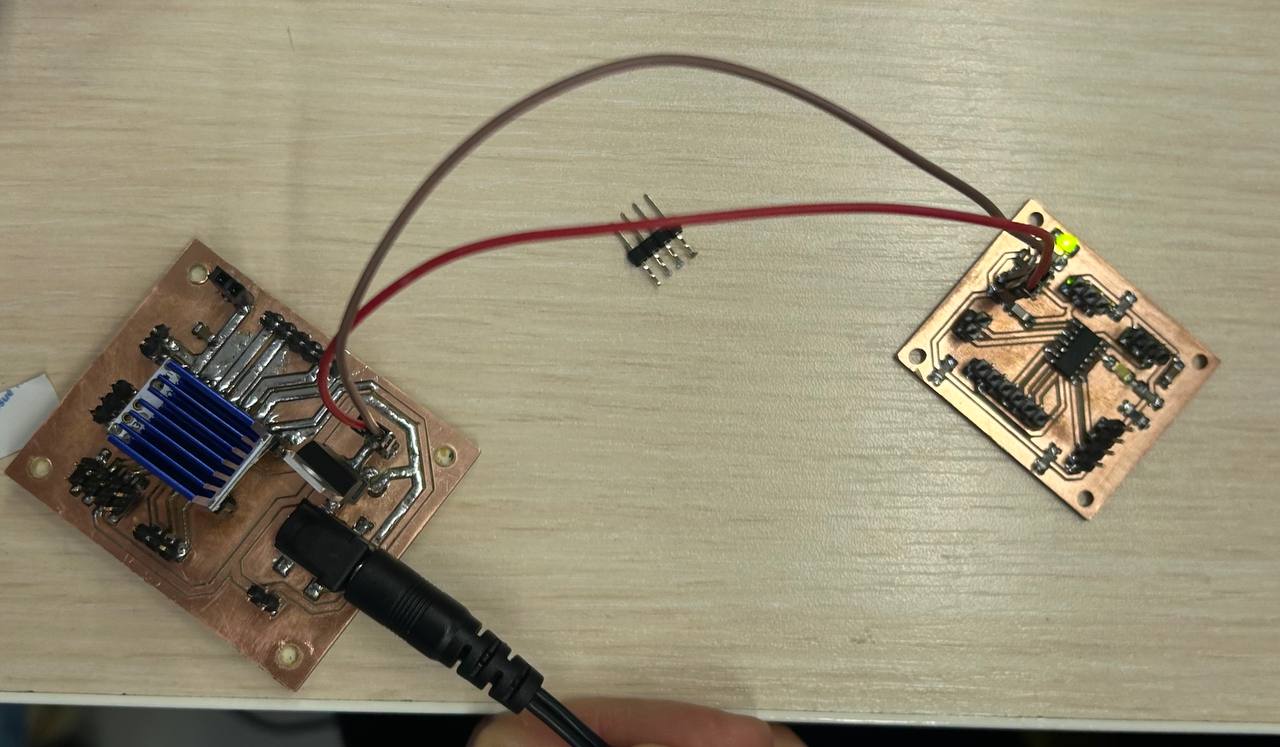
Final shot of PCB board.
Conclusion
This week was a bit more challenging for me than Electronics design week. I designed the board that I already had sketched but there were a lot of things to struggle with.
Regulator as a component was the most difficult, as it was burning every time and was problematic. Turning 12V to 5V was hard to get. But I did it. And did other things too.
I spent more time on cutting right pcb and in soldering components on it. Also I knew about output devices like displays, motors…