6. Embedded programming
Group Assignment
For our group assignment we started from comparing 2 programming languages and 2 microcontrollers.
-
C++
-
Micropython
-
ATtiny microcontroller, more than 10 times slower than RP2040
-
Xiao RP2040 microcontroller
Working with ATtiny microcontrollers requires some adaptation compared to larger Arduino boards, but they offer a cost-effective and space-saving solution for many projects, especially those with minimal requirements.
The Xiao RP2040 is a microcontroller board based on the Raspberry Pi RP2040 microcontroller chip. It offers a powerful yet compact platform for building a wide range of projects.
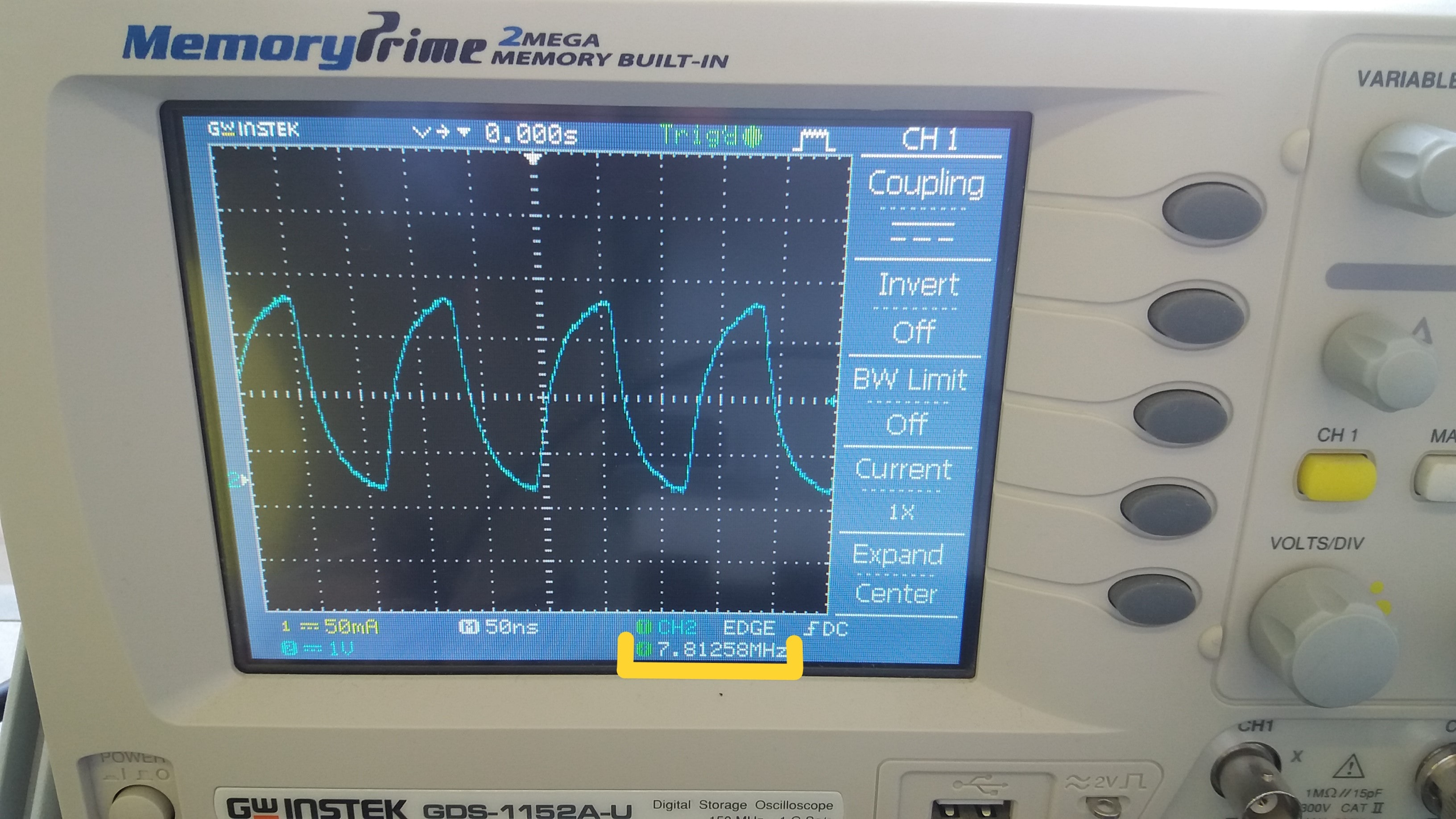
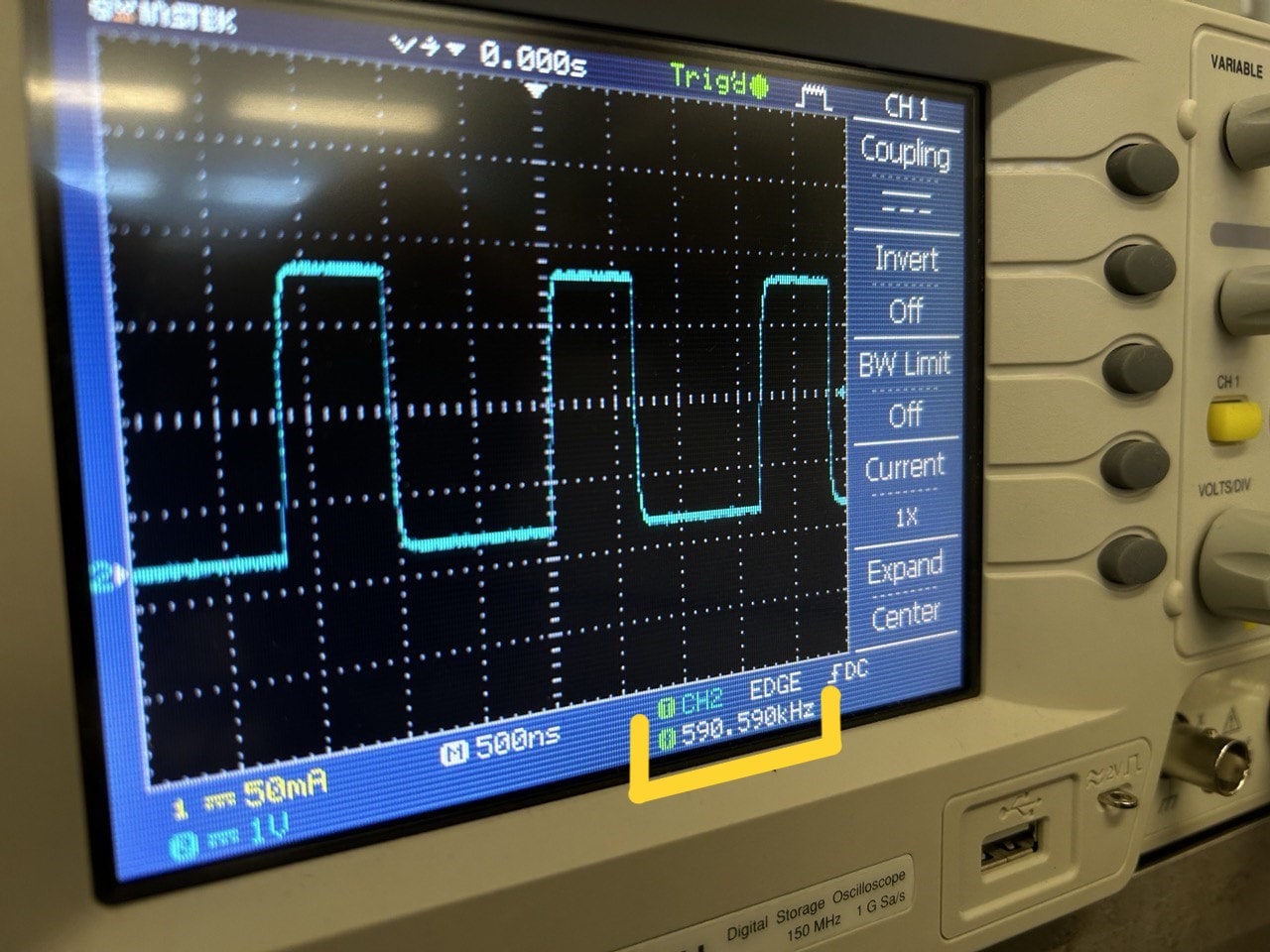
We tried oscilloscope,
the test aimed at understanding the speed difference between a program using the Arduino environment (pinMode(), digitalWrite(), etc) and a program written “bare metal”, “talking” directly to the registers. wW got 500kHz by Elen’s Arduino environment based code and with mine (bare metal code) 7.8MHz.
Here’s bare metal version:
int main() {
        /*
        0x400140d4: GPIO26_CTRL: GPIO 26 control including function select and overrides.
        0x05: from "2.19.2. Function Select": selects function SIO (Single-Cycle IO)
        */

        // same for GPIO26_CTRL
        *((volatile unsigned int*) 0x400140d4) = 0x05;

        /*
        Output enable registers, GPIO_OE and GPIO_HI_OE, are used to enable the output driver. 0 for high-impedance, 1
        for drive high/low based on GPIO_OUT and GPIO_HI_OUT.
        sets the 27th bit of this register to 1 in order to enable output
        */
        *((volatile unsigned int*) 0xd0000020) = (1 << 26);  // GPIO_OE


        while( 1 )
        {
          //toggles the pin 26 high and low
          *((volatile unsigned int*) 0xd000001c) ^= ( 1 << 26);
        }

        return 0;
}
And Elen’s:
void setup() {
  // put your setup code here, to run once:
  pinMode(26,OUTPUT);
}

void loop() {
  // put your main code here, to run repeatedly:
  digitalWrite(26, HIGH);
  digitalWrite(26,LOW);
}
Programming with Micropython and C++
Xiao RP2040 microcontrollers can be programmed by Micropython. Arduino language is based on C++ language.
What setup() and loop() mean.
setup() and loop() are two basic functions that every Arduino code must have:
The setup() function is called once when the Arduino board is activated or reset. It is used for initialization variables, pin modes, libraries, and other settings required for your code. All in the setup() function will run only once at the beginning of your program. Here’s an example how setup() function is used:
void setup() {
  // Declare pins as output:
  pinMode(stepPin, OUTPUT);
  pinMode(dirPin, OUTPUT);
  Serial.begin(9600);
}
#define and const
syntaxes when you write #define after write name and after pin number (it used only for pin, to name the number of pin). For example, before starting coding my stepper motor, I made 2 defines for direction Pin and step Pin.
Define stepper motor connections and steps per revolution:
#define dirPin 1
or
#define stepPin 2
#define is similar to const int but it differs that const int defines a variable and #define “copy pastes” the value in the code.
it is recommended to name pin, so if the pin number change, you will not have to change every single number in your whole code.
int-integer is to write the numbers - you give value to the number. int can’t understand not natural numbers, like 12.75, 5.2, … but only 12,13,14 …
float can be 12.75, 5.2, …
millis() [Time]
Returns the number of milliseconds passed since the Arduino board began running the current program. This number will overflow (go back to zero), after approximately 50 days. after I found syntax for counting time from when board started running its current program, I asked chatgpt to show me where I can watch the result. And the answer was - In serial monitor (serial monitor is connection channel)
tools>>serial monitor>>9600baud (a specific communication speed used for serial communication between Arduino board and computer) what’s being used in general
In serial monitor section I wrote a code from link, and pushed enter. After chatgpt helped me and wrote the code, serial begin/printin/delay… and I started noticing in serial monitor section numbers like 1790000… numbers - these are milliseconds. It starts counting from the time I connected microcontroller to my notebook.
Also I learned about while and for. They are primitive loop commands.
While is a command in which it keeps running a block of code as long as certain condition is true.
For statement is used to repeat a block of statements enclosed in curly braces. An increment counter is usually used to increment and terminate the loop. The for statement is useful for any repetitive operation, and is often used in combination with arrays to operate on collections of data/pins.
In Arduino next to “int” if you don’t write “const”, then it is changeable and after it in below you can write anything else with the same name by “int”.
include tool - when you do include it is including for example servo - to understand servo motor
Pulse Width Modulation
We learned what PWM is.
Pulse Width Modulation - It’s a method used to generate analog. PWM is generally used in microcontroller - based systems for controlling the speed of motors, the brightness of LEDs, and the position of servo motors, etc.
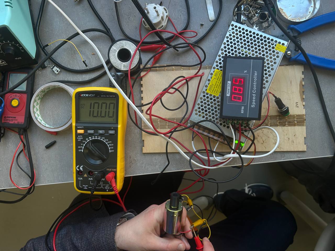
We switched a motor to speed controller that you can control for example by which percentage of his power to use. By multimeter you can see Volt of usage. After we talked about frequency, Hertz, analog and digital signals.
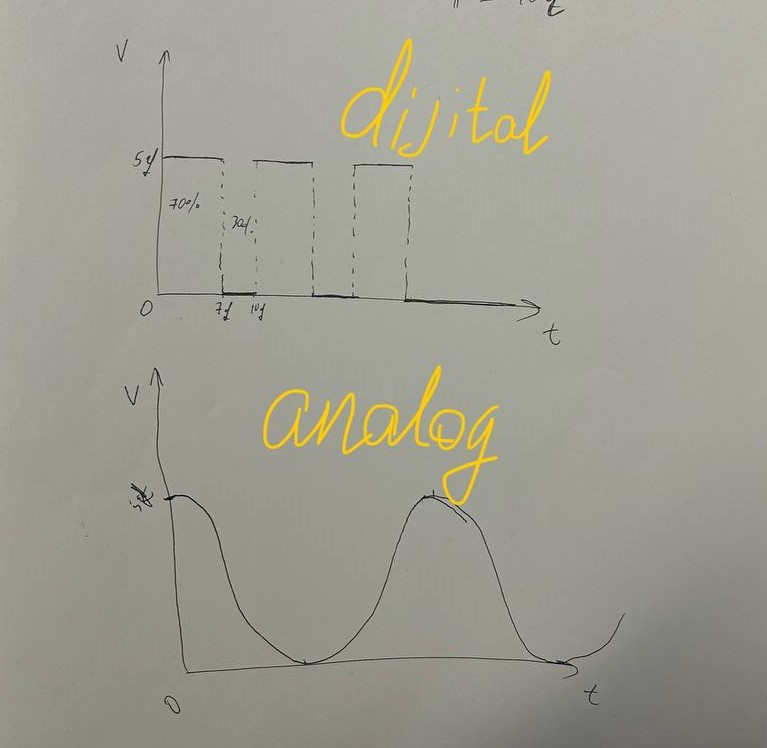
- An analog signal is a continuous signal that varies smoothly over time. It can take any value within a certain range and is typically represented by a waveform. In the context of frequency, an analog signal might refer to a continuous sine wave or any other continuous waveform with varying frequency.
- A digital signal is a discrete signal that can only take on a finite number of values. It is typically represented by a sequence of binary digits (bits), where each bit represents a discrete value (0 or 1). In the context of frequency, a digital signal might refer to a series of pulses where the frequency represents the rate at which the pulses occur.
Individual Assignment
What you need for connecting stepper motor to microcontroller
Motor has to have his separately power supply. Motor is working with driver.
Why you have to make work motor only with driver?
Stepper motors require drivers for several crucial reasons:
-
Current and Voltage Requirements: Stepper motors typically require higher currents and voltages than what microcontrollers like Arduinos can safely provide. Supplying insufficient power could damage both the microcontroller and the motor itself. Drivers act as intermediaries, amplifying the control signals from the microcontroller to the level necessary to drive the motor effectively.
-
Direction Control: Stepper motors achieve precise movement by energizing coils in a specific sequence. Microcontrollers often lack the capability to directly control multiple high-power outputs simultaneously in the required sequence. Drivers handle this complexity, translating simple control signals from the microcontroller into the appropriate sequence and timing for the motor coils.
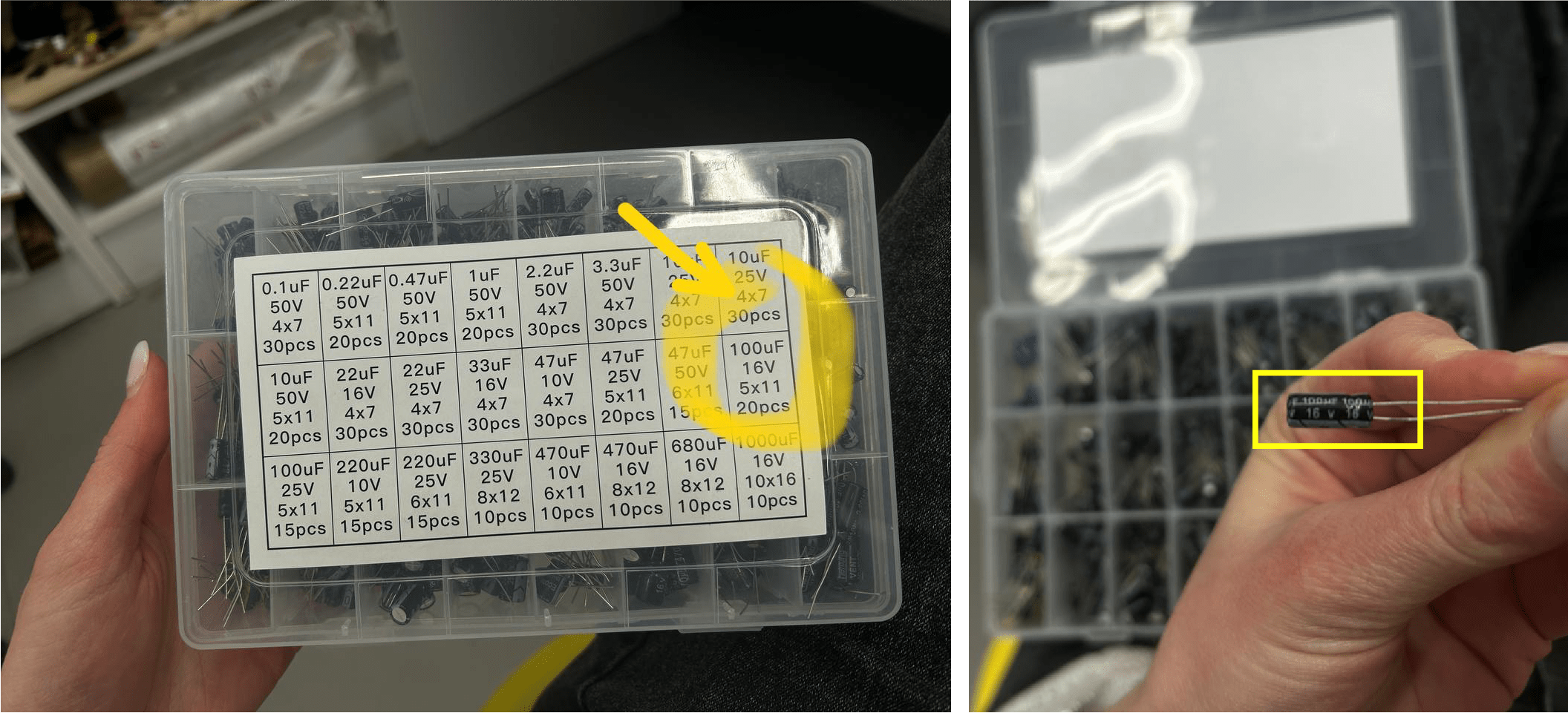
For making motor work, you need a charger, and after capacitor which will be used to low noises that are not needed and to save some energy and if energy will be needed, it will take from his collected energy.
After it’s a driver - plus and minus is charging by charger, 4 other pins are pined to motor. and only 2 of them goes to pcb board from driver. One of them is digital and other is digital with pwm.
To know how much volt and amper needs your motor, you have to check it in datasheet.
One of the variants is that you need a battery, for power: there has to be like phone has indigenous working with usb charger, or like cuadrocopter (when you have to take off battery and put another one).
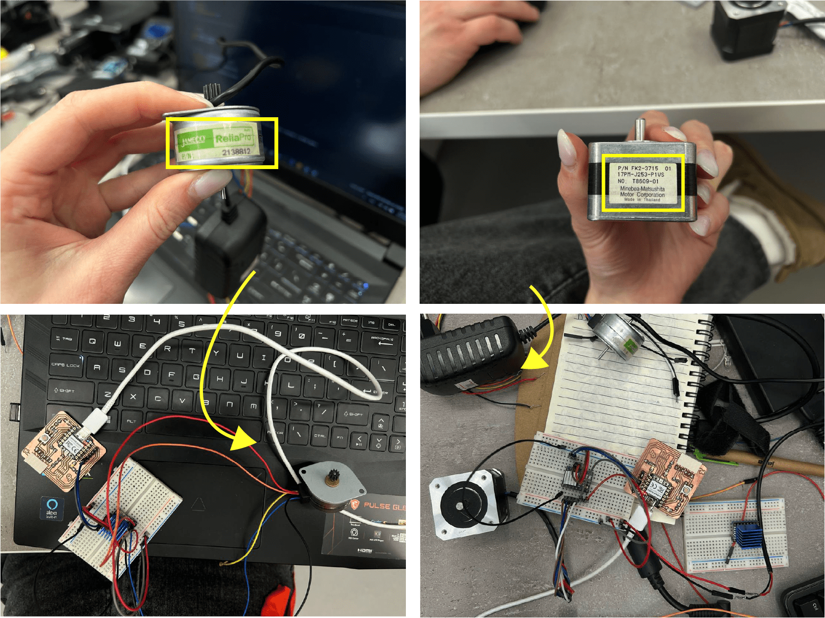
I tried to program 2 different motors with different step count.
- One of them was JAMECO, the other one - NEMA.
- Driver - LERDGE TMC2225 Driver
- USB cable type A/B
- Capacitor
- Breadboard
- Jumper wires
I tried some connections with 2 motors parallel. Just to know that all is working.
After started to assemble all needed components with help of this website. - How to control a stepper motor with DRV8825 driver and Arduino.
Adding capacitor to our breadboard.
Also I used voltage regulator.
While both the LM2596 and REG 5V SOT223 can regulate voltage, the LM2596 is a buck converter that is more efficient but potentially more complex, while the REG 5V SOT223 is a linear regulator that is simpler but less efficient, especially in terms of heat dissipation. The choice between them depends on the specific requirements and constraints of the application.
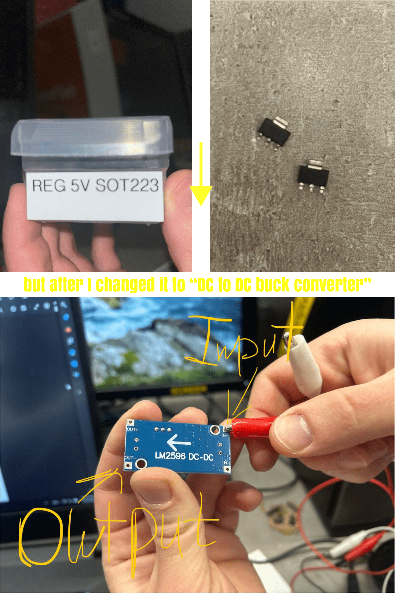
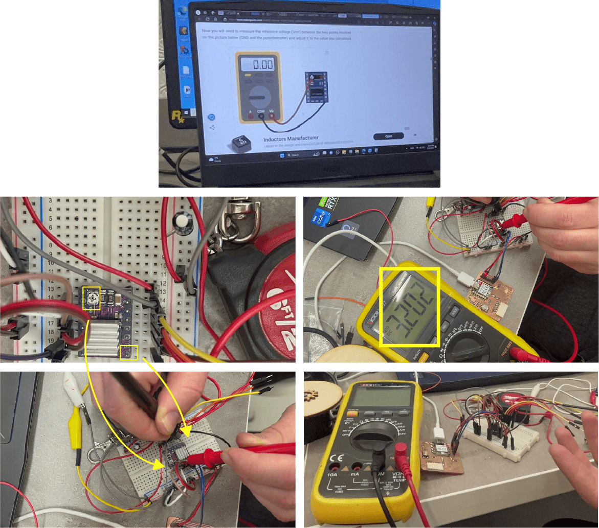
So after we have to understand does our driver can make the voltage, the force of current pass through itself. When we solve all this, after we had to regulate the driver, so that it will give the amperage that I want. We can turn on the motor and by screwing with small screwdriver rotate and give the voltage visually, or do it with multimeter as we did below.
- LM2596 is a DC to DC buck converter, meaning it steps down voltage from a higher level to a lower level.
- REG 5V SOT223 is a linear voltage regulator, which reduces voltage without changing its polarity.
Writing a code for stepper motor
After I made all connections for stepper motor, driver, capacitor and microcontroller, I started my coding journey.
In Arduino there are libraries for stepper motor, but these libraries are taking up a lot of space.
So I wrote my program code without using libraries.
The main points are stepPin and dirPin.
• “StepPin” refers to the pin on a microcontroller or stepper motor driver that is used to send step pulses to the stepper motor. Each step pulse causes the motor to move a small increment. • “DirPin” refers to the pin used to control the direction of rotation of the stepper motor. By toggling the state of this pin, you can make the motor rotate clockwise or counterclockwise.
Also I set the step revolution.
“Step revolution” typically refers to the movement of a stepper motor in terms of individual steps. Each step revolution represents one complete rotation of the motor shaft divided into a specific number of steps. The number of steps per revolution depends on the motor’s design and its associated driver/controller settings.
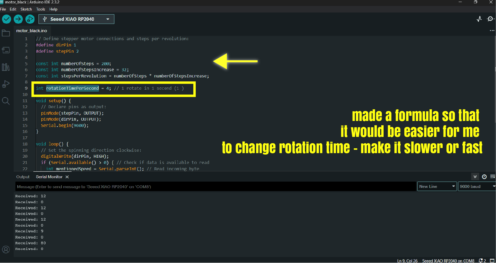
What is rotation time per second. That means - for one rotation it will be spend 4 second. in 4 sexond motor will rotate 1 time.
I created a serial connection with a baud rate of 9600. After I wrote that
  if (Serial.available() > 0) { // Check if data is available to read
    int mentionedSpeed = Serial.parseInt(); // Read incoming byte
    Serial.print("Received: ");
    Serial.println(mentionedSpeed); // Print received character
    rotationTimePerSecond = mentionedSpeed;
  }
So in serial monitor we can change rotation time per second to the number that we will write there.
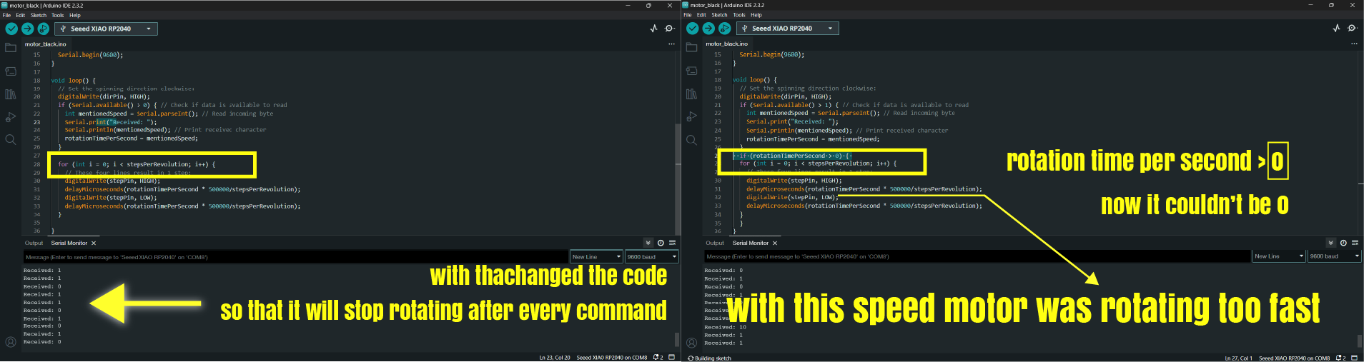
and we are creating condition that if rotation time per second is bigger than 0, motor has to rotate:
 if (rotationTimePerSecond > 0) {
  for (int i = 0; i < stepsPerRevolution; i++) {
    // These four lines result in 1 step:
    digitalWrite(stepPin, HIGH);
    delayMicroseconds(rotationTimePerSecond * 500000/stepsPerRevolution);
    digitalWrite(stepPin, LOW);
    delayMicroseconds(rotationTimePerSecond * 500000/stepsPerRevolution);
  }
  }
Trying stepper motor in work
After I tested my motor.
After I started experimenting with speed.
Below you can see final code of NEMA stepper motor. I brought it and did some changes from Rudolf’s website.
// Define stepper motor connections and steps per revolution:
#define dirPin 1
#define stepPin 2

const int numberOfSteps = 200;
const int numberOfStepsIncrease = 32;
const int stepsPerRevolution = numberOfSteps * numberOfStepsIncrease;

int rotationTimePerSecond = 7; // 1 rotate in 4 second (1 )

int micPin = 28; // Analog pin connected to microphone

void setup() {
  // Declare pins as output:
  pinMode(stepPin, OUTPUT);
  pinMode(dirPin, OUTPUT);
  Serial.begin(9600);
}

void loop() {
  // Set the spinning direction clockwise:
  digitalWrite(dirPin, HIGH);
  if (Serial.available() > 0) { // Check if data is available to read
    int mentionedSpeed = Serial.parseInt(); // Read incoming byte
    Serial.print("Received: ");
    Serial.println(mentionedSpeed); // Print received character
    rotationTimePerSecond = mentionedSpeed;
  }
  if (rotationTimePerSecond > 0) { z
  for (int i = 0; i < stepsPerRevolution; i++) {
    // These four lines result in 1 step:
    digitalWrite(stepPin, HIGH);
    delayMicroseconds(rotationTimePerSecond * 500000/stepsPerRevolution);
    digitalWrite(stepPin, LOW);
    delayMicroseconds(rotationTimePerSecond * 500000/stepsPerRevolution);
  }
  }
}
Below you can see code of Jameco Unipolar stepper motor.
/* Example sketch to control a stepper motor with
   A4988/DRV8825 stepper motor driver and
   Arduino without a library.
   More info: https://www.makerguides.com */

// Define stepper motor connections and steps per revolution:
#define dirPin 1
#define stepPin 2
#define stepsPerRevolution 1536

void setup() {
  // Declare pins as output:
  pinMode(stepPin, OUTPUT);
  pinMode(dirPin, OUTPUT);
}

void loop() {
  // Set the spinning direction clockwise:
  digitalWrite(dirPin, HIGH);

  // Spin the stepper motor 1 revolution slowly:
  for (int i = 0; i < stepsPerRevolution; i++) {
    // These four lines result in 1 step:
    digitalWrite(stepPin, HIGH);
    delayMicroseconds(500000/stepsPerRevolution);
    digitalWrite(stepPin, LOW);
    delayMicroseconds(500000/stepsPerRevolution);
  }

  delay(1000);

  // Set the spinning direction counterclockwise:
  digitalWrite(dirPin, LOW);

  // Spin the stepper motor 1 revolution quickly:
  for (int i = 0; i < stepsPerRevolution; i++) {
    // These four lines result in 1 step:
    digitalWrite(stepPin, HIGH);
    delayMicroseconds(500000/stepsPerRevolution);
    digitalWrite(stepPin, LOW);
    delayMicroseconds(500000/stepsPerRevolution);
  }

  delay(1000);

  // Set the spinning direction clockwise:
  digitalWrite(dirPin, HIGH);

  // Spin the stepper motor 5 revolutions fast:
  for (int i = 0; i < 5 * stepsPerRevolution; i++) {
    // These four lines result in 1 step:
    digitalWrite(stepPin, HIGH);
    delayMicroseconds(500000/stepsPerRevolution);
    digitalWrite(stepPin, LOW);
    delayMicroseconds(500000/stepsPerRevolution);
  }

  delay(1000);

  // Set the spinning direction counterclockwise:
  digitalWrite(dirPin, LOW);

  //Spin the stepper motor 5 revolutions fast:
  for (int i = 0; i < 5 * stepsPerRevolution; i++) {
    // These four lines result in 1 step:
    digitalWrite(stepPin, HIGH);
    delayMicroseconds(500000/stepsPerRevolution);
    digitalWrite(stepPin, LOW);
    delayMicroseconds(500000/stepsPerRevolution);
  }

  delay(1000);
}
0.91 INCH OLED Display
Interfacing 0.91 INCH OLED Display with Arduino
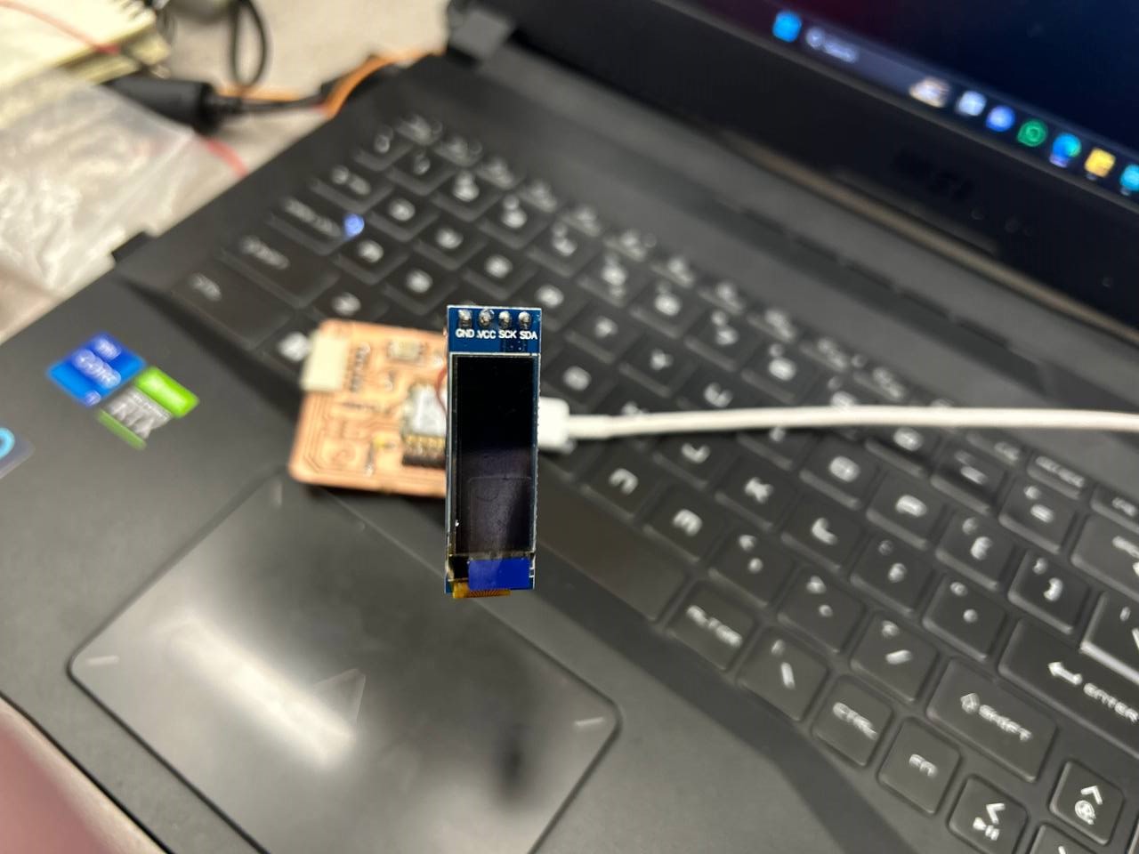
I tried to us this OLED but as soon as I connect it to my board, it burnt, so I couldn’t try to program it.
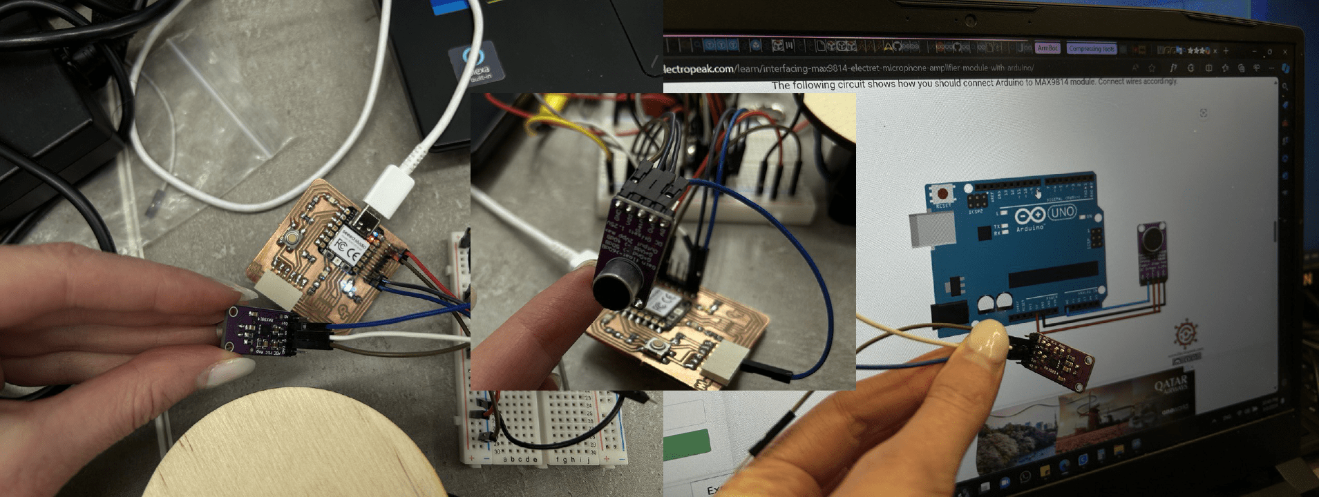
Electret Microphone Amplifier Module
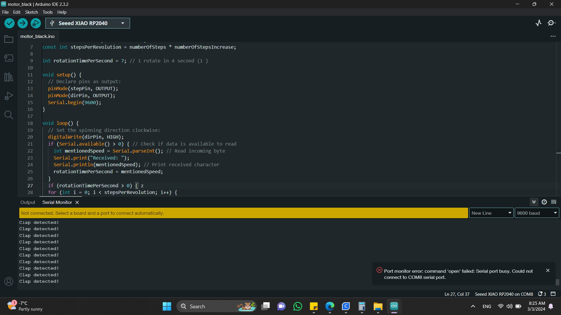
After I tried a microphone with my stepper motor, to work. I wanted to code a program so that after every clap my motor would start to work.
Unfortunately my microphone was detecting every noise as aa clap and my motor was working unstoppable.
Here is the code of microphone separately:
// the setup routine runs once when you press reset:
void setup() {
// initialize serial communication at 9600 bits per second:
Serial.begin(9600);
}
// the loop routine runs over and over again forever:
void loop() {
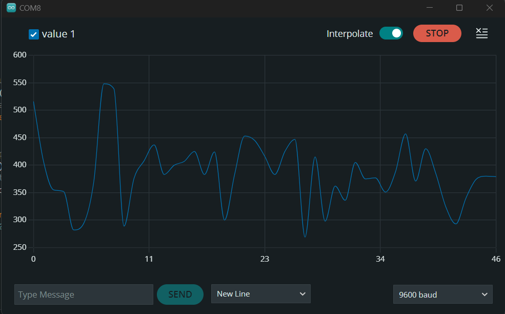
// read the input on analog pin 0:
int sensorValue = analogRead(28);
// print out the value you read:
Serial.println(sensorValue);
delay(10);
}
There’s thias code for microphone programming added to my stepper motors code.
Introduction - Adafruit AGC Electret Microphone Amplifier - MAX9814
Also I started this week’s assignment on 4th week.
Conclusion
This week was very challenging for me. I used things that were not familiar to me. After some weeks I think that I will make a better insight about writing a code. C++ seems not so hard, but when you are writing a longer code, it starts to be messy.
Microphone programming was the hardest part and if there were more time, I would like to explore this part better than I did, cause at first I wanted to make it detect the voice.