13. Networking and communications
For this week assignment I decided to use WEMOS S2 Mini which is a compact WiFi development board based on the ESP32-S2FN4R2 chip.
Group Assignment
For our Group assignment, we experimented with the I2C communication interface between our boards. The components we used included ATtiny1614 boards, a UPDI programmer with RP2040, a joystick, and two LEDs.
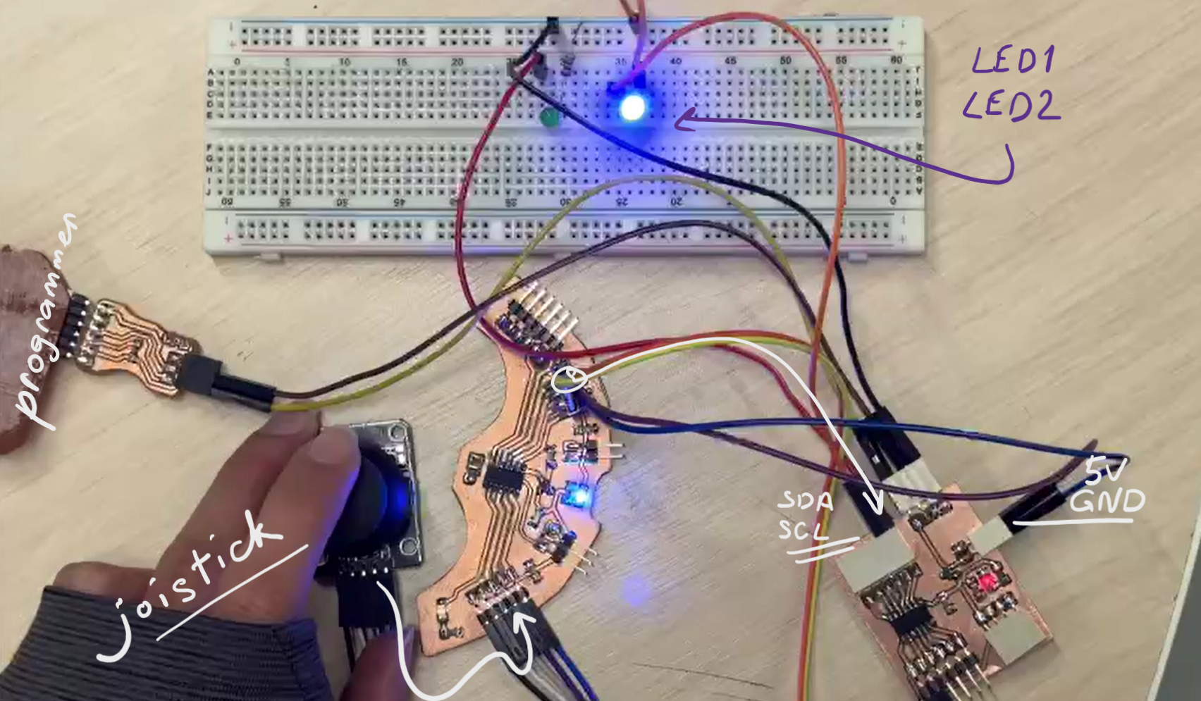
Initially, we established communication between the boards using the I2C protocol. Later, we connected a joystick to the primary board, and two LEDs were linked to the secondary board.
The primary board’s code operates as follows: If the joystick’s X and Y coordinates are non-zero, it sends the X value to the secondary board. However, when both coordinates are zero, the primary board transmits the value 0.
And when the secondary board receives data from the main board, it follows this logic: If the data value is positive, the first LED illuminates while the second one remains off. Conversely, if the data value is negative, the second LED lights up, and the first LED turns off.
Result of it you will see in our group page.
Individual Assignment
WEMOS S2 Mini
At first I tried to try it, so I will be sure it’s working and I was able to upload a code in it. It was a bit problematic at first, I couldn’t understand what’s the problem of not uploading even the simplest code, but after I fixed it somehow.
All the process of connecting this board to Arduino IDE software I asked CoPilot.
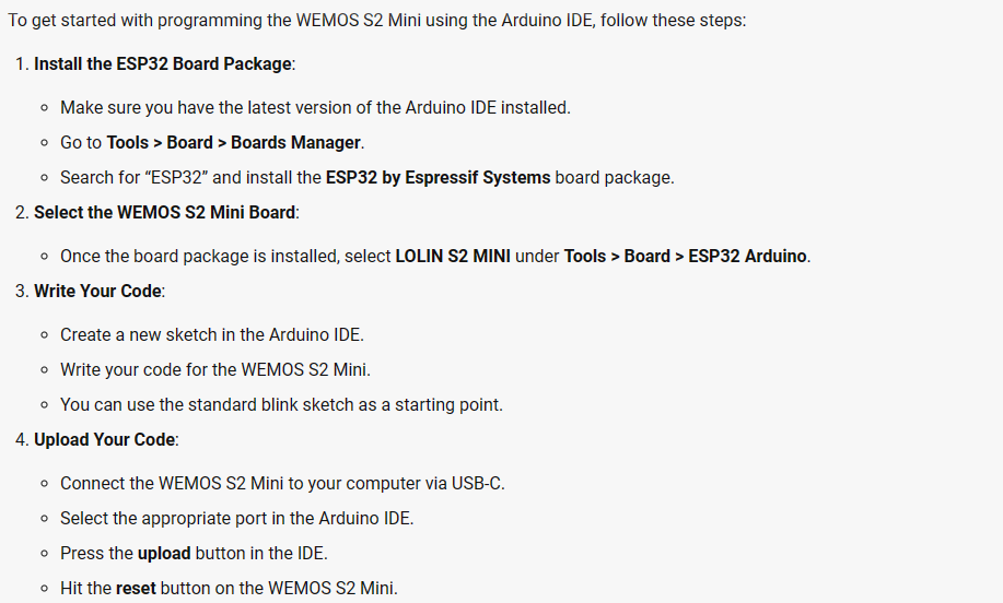
After installing the ESP32 by Espressif Systems board package I tried to upload the code that CoPilot wrote, but it was not uploading.
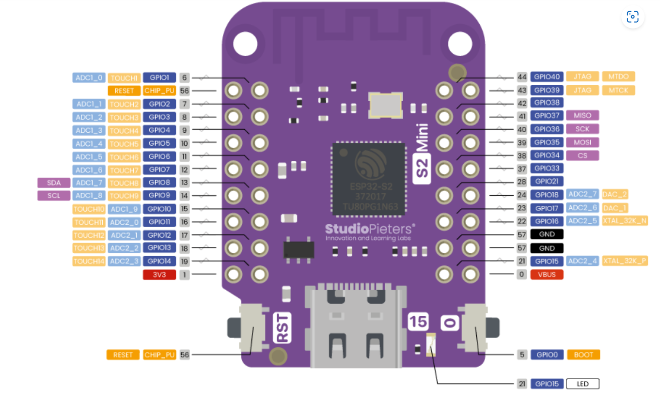
So I just tried to use the blinking code. The LED pin number I found here.
Here you can see that it worked,
PCB Board Design
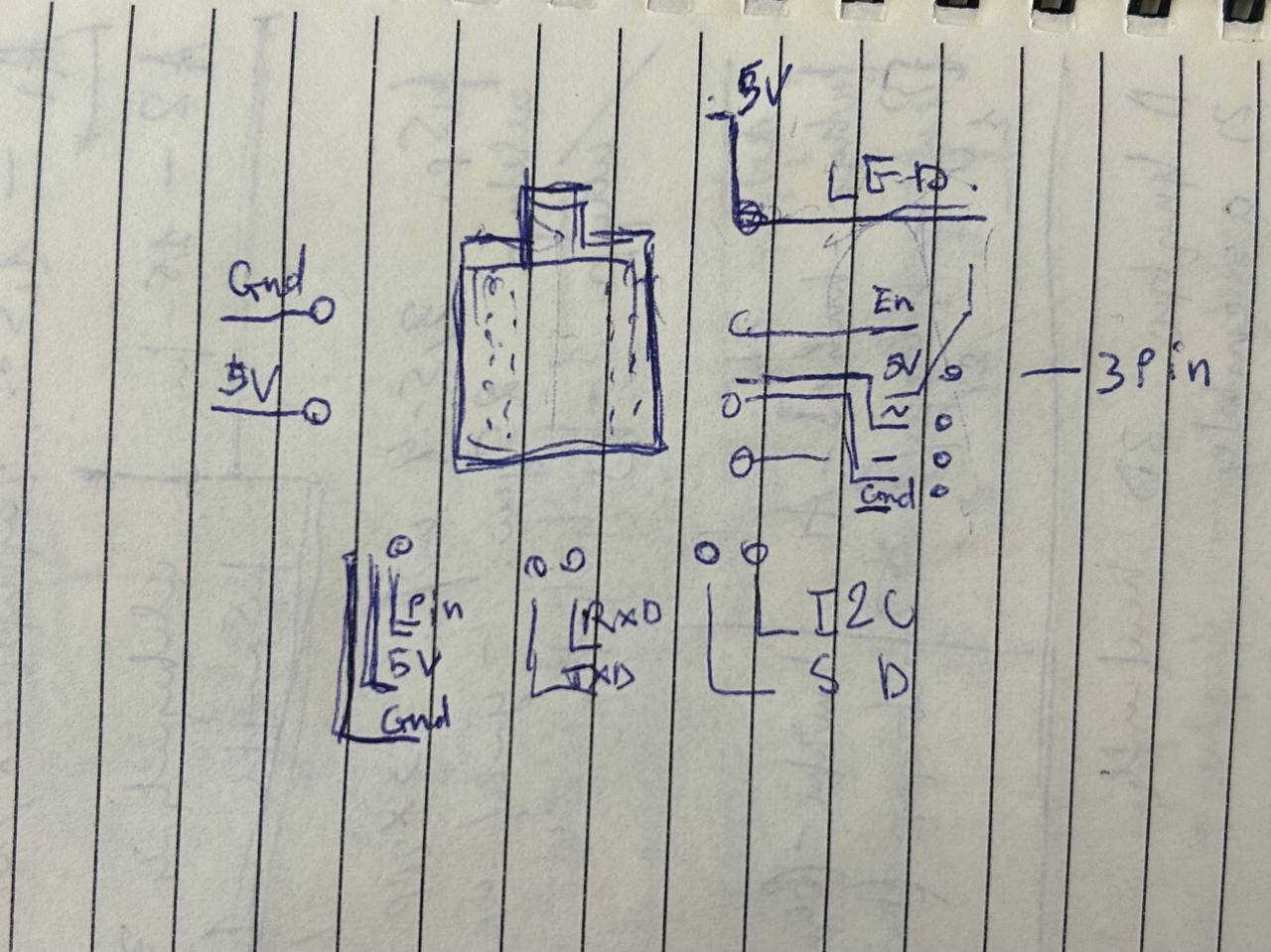
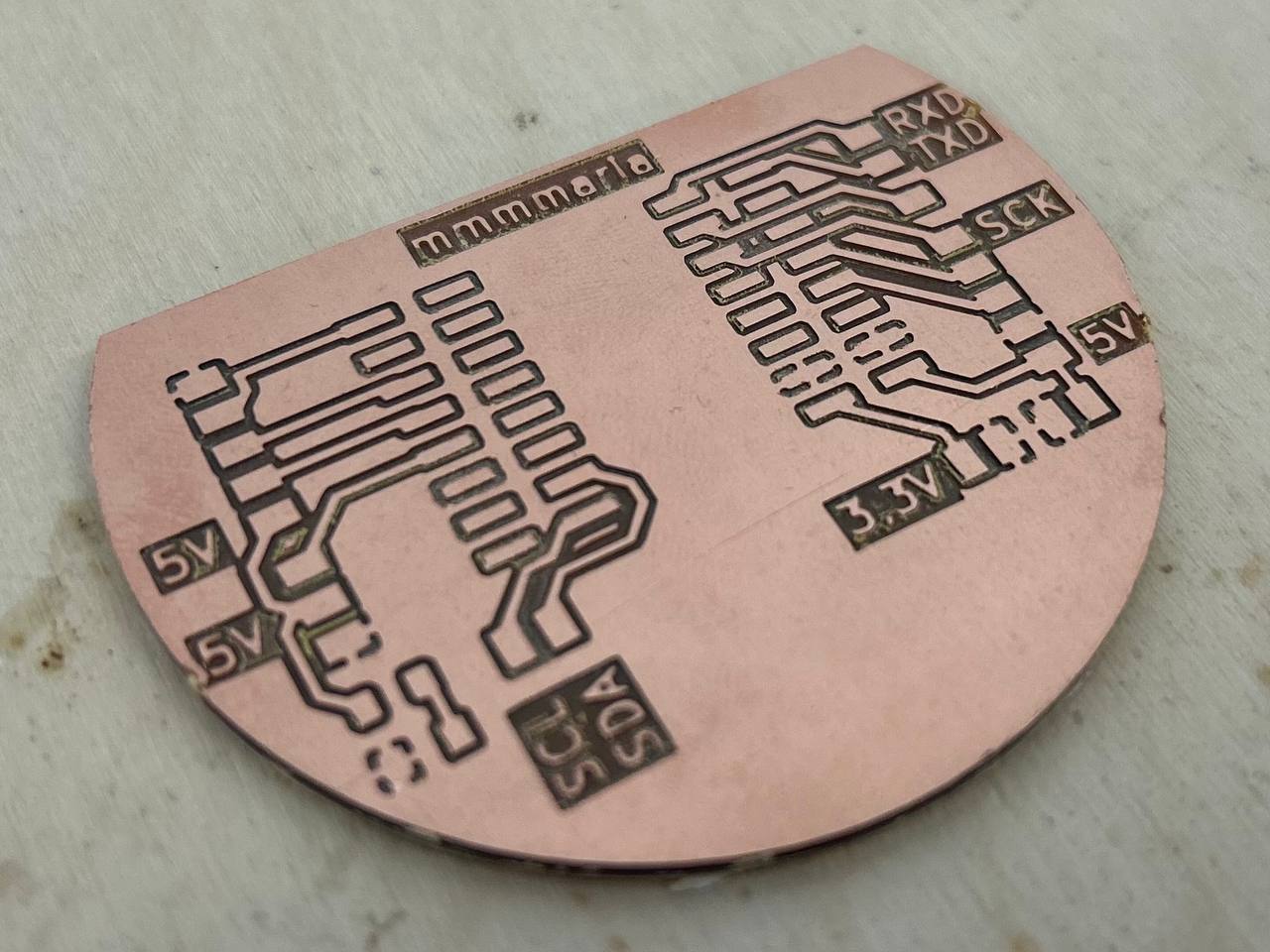
and after I started designing my PCB in KiCad. At first I draw a sketch, to clearly know what I will need in my PCB.
And searched for S2Mini board footprint with ESP32 microcontroller, the only footprint was this ESP32 footprint.
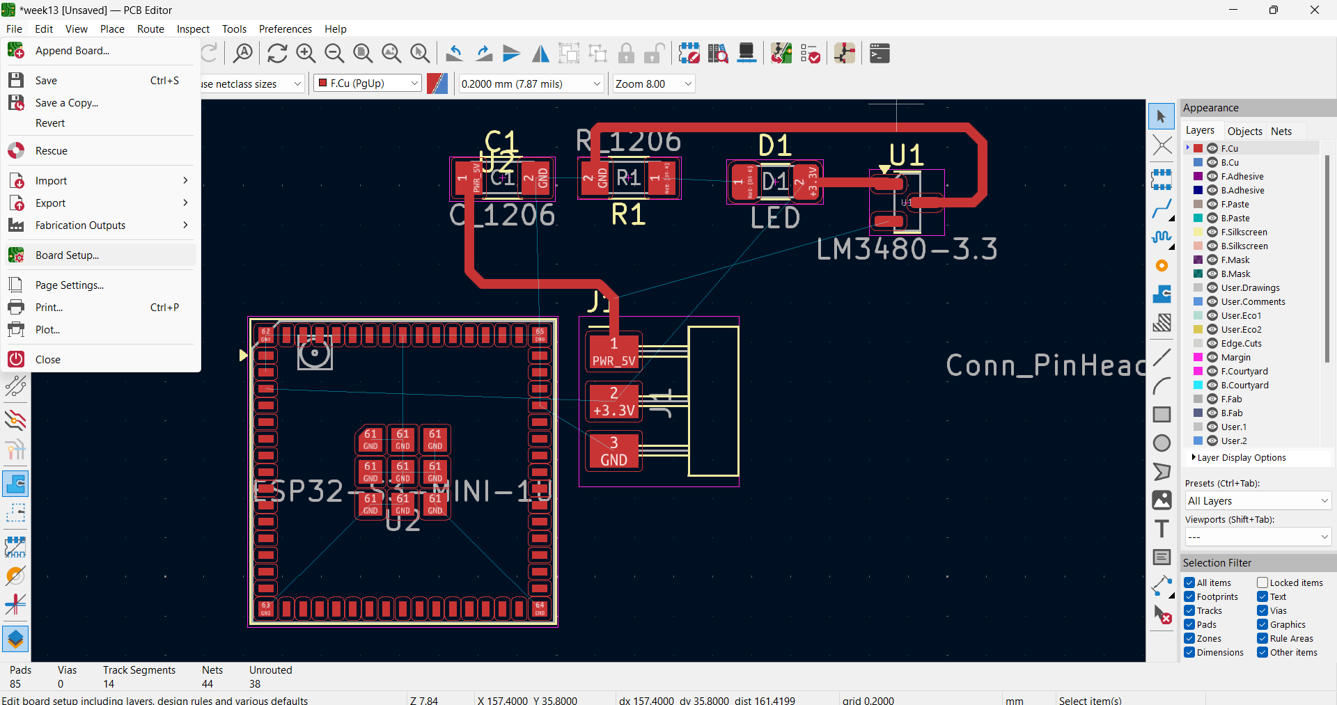
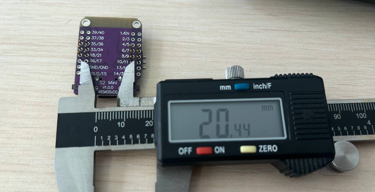
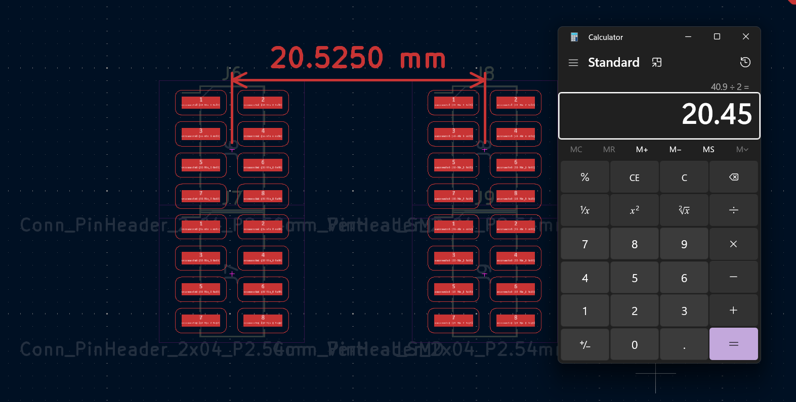
As I didn’t find it, I tried to measure the distance between pins and put SMD connectors instead of board’s footprint.
And started designing my board with this connectors.
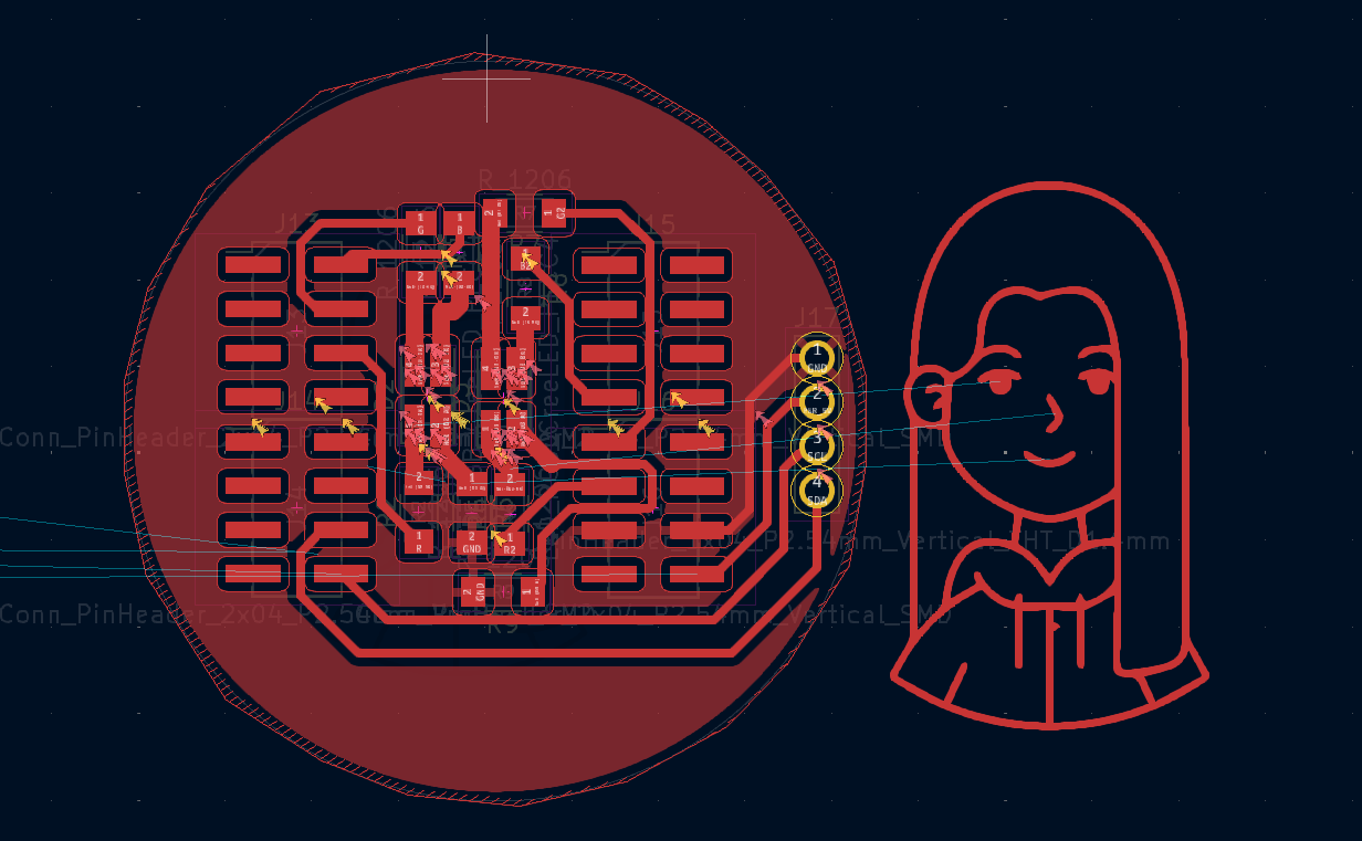
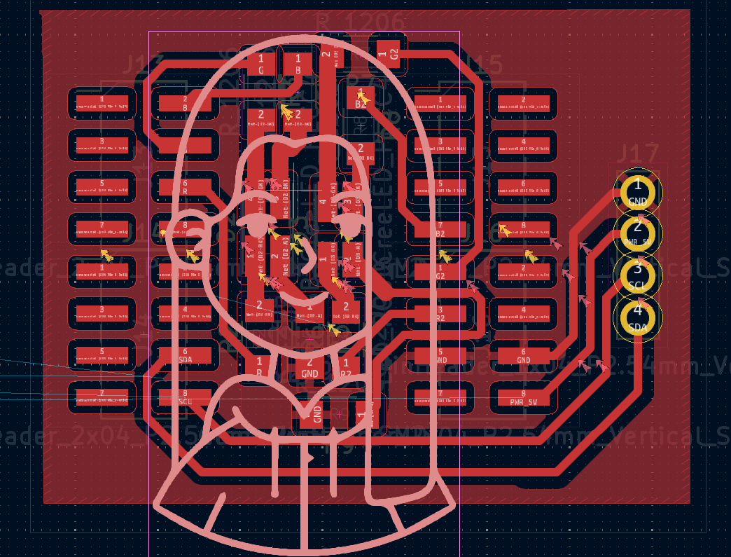
The result was not bad, and I had some space. I decided to put an image on my board and for that I downloaded a PNG icon and made it a vector file (SVG) and from Files >> Import >> SVG I put this icon on my board.
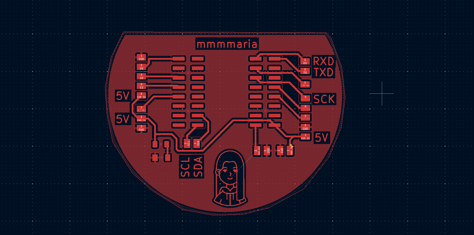
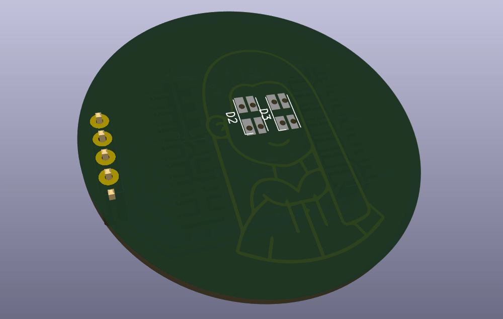
Then I had an idea to put LEDs on this girl icon’s eyes. BuT I understood that there is not so much space to add resistors for LEDs too. And as I chose RGB LED, there had to be 4 resistors.
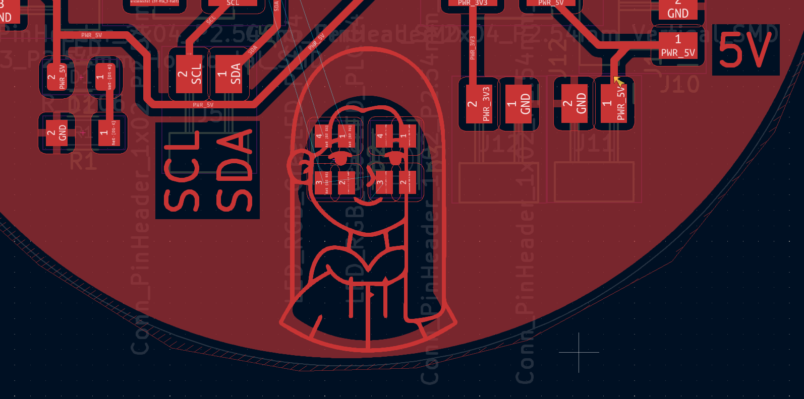
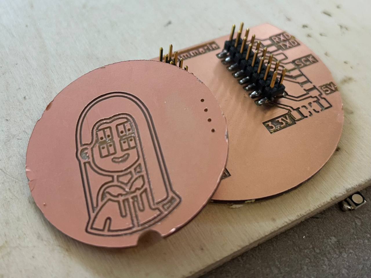
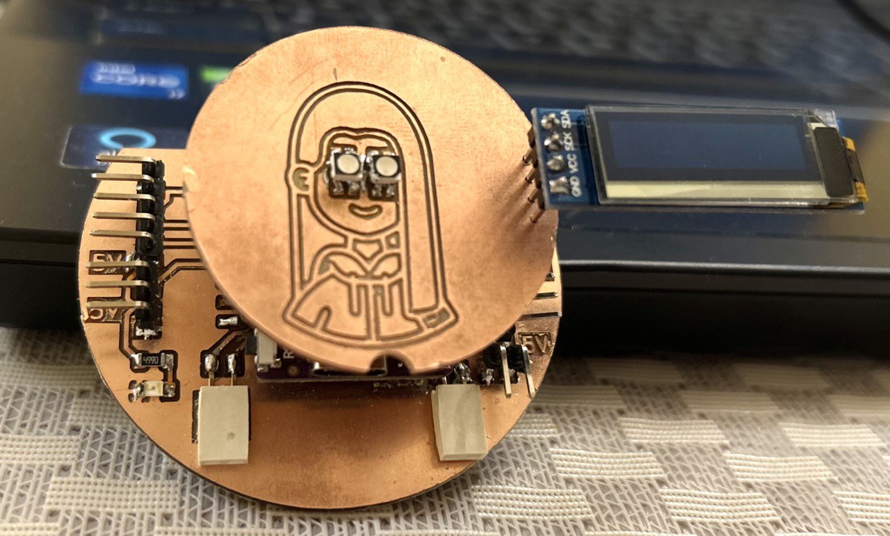
So I decided to adjust this icon, and make a separate board in which there will be my girl icon with LED lights on eyes. And for this week’s assignment I also added display pins on it.
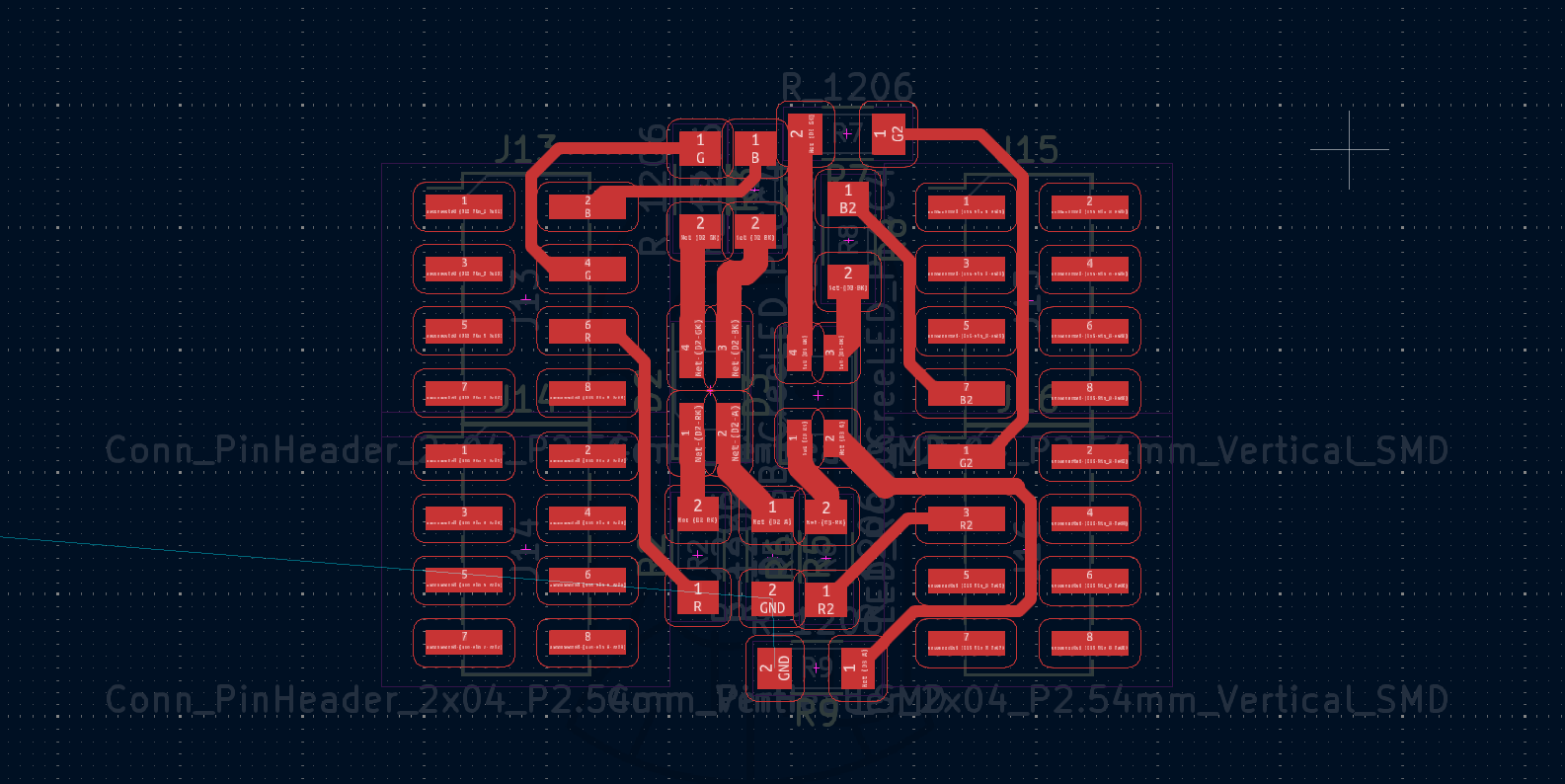
My board is 2 sided, so that the Top side will be only shapes of girl and LEDs, and the bottom side there will be resistors and connectors.
Testing components
At first I tried to make my RGB PLCC4 Led work. I soldered connectors.
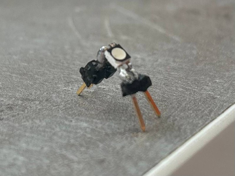
And tried it with Arduino board.
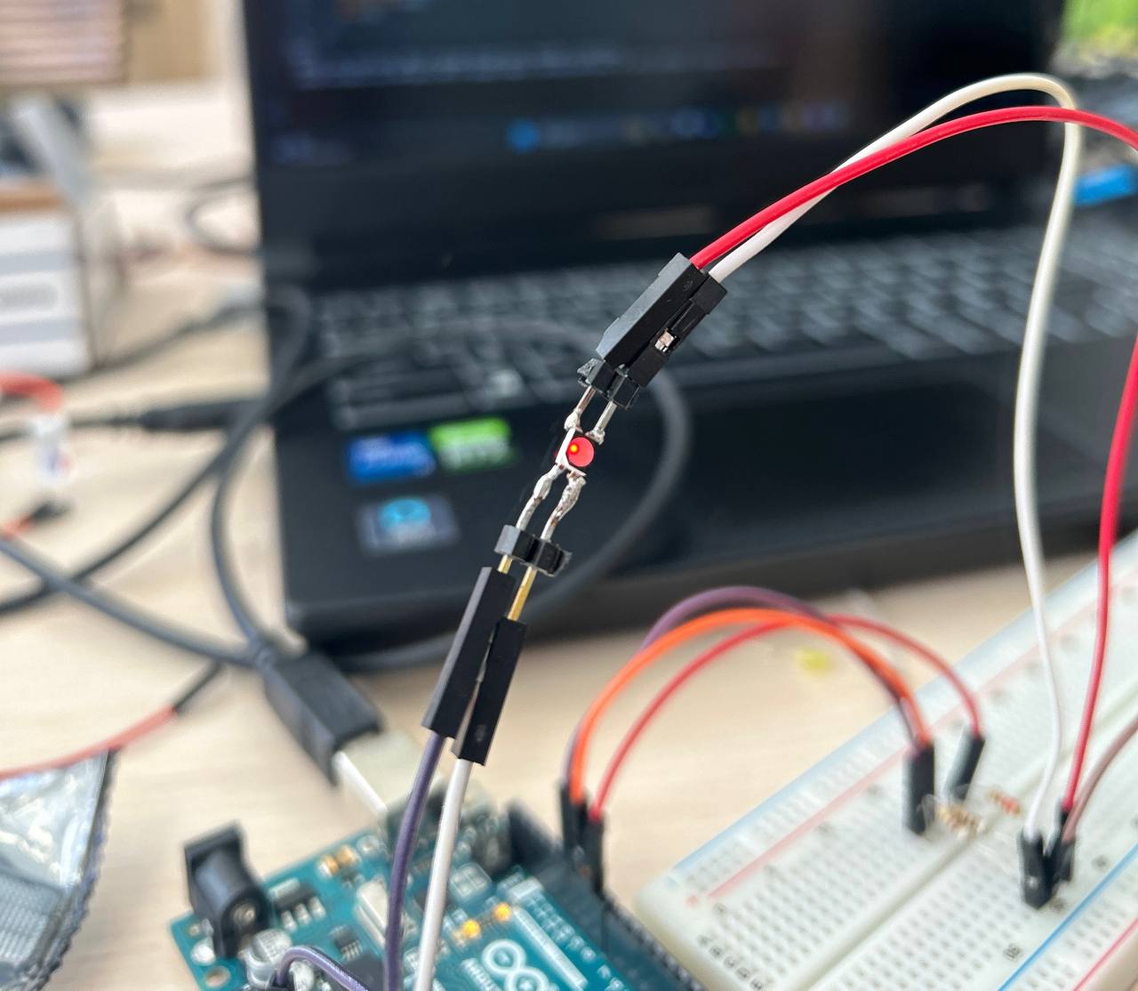
So I understood what type of pins I will need.
PLCC4 LEDs are working with 3 pins and 1 GND.
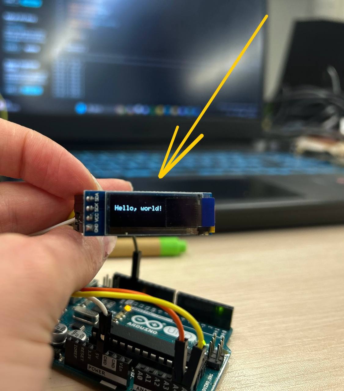
And after I also tried the display which I will use on my board.
For making 2-side board I needed to mirror some components in the other side by clicking F on keyboard. It will move mirrored components to B.Cu .
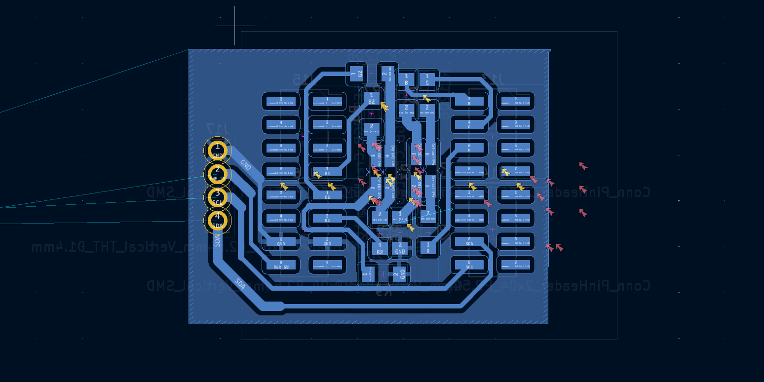
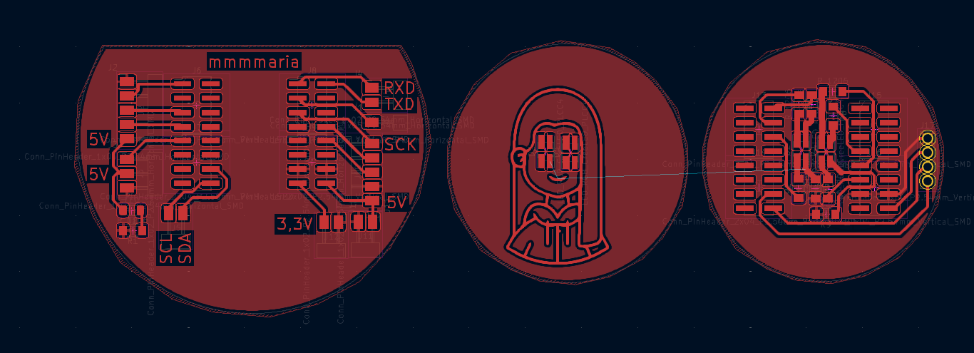
So this is my base board.
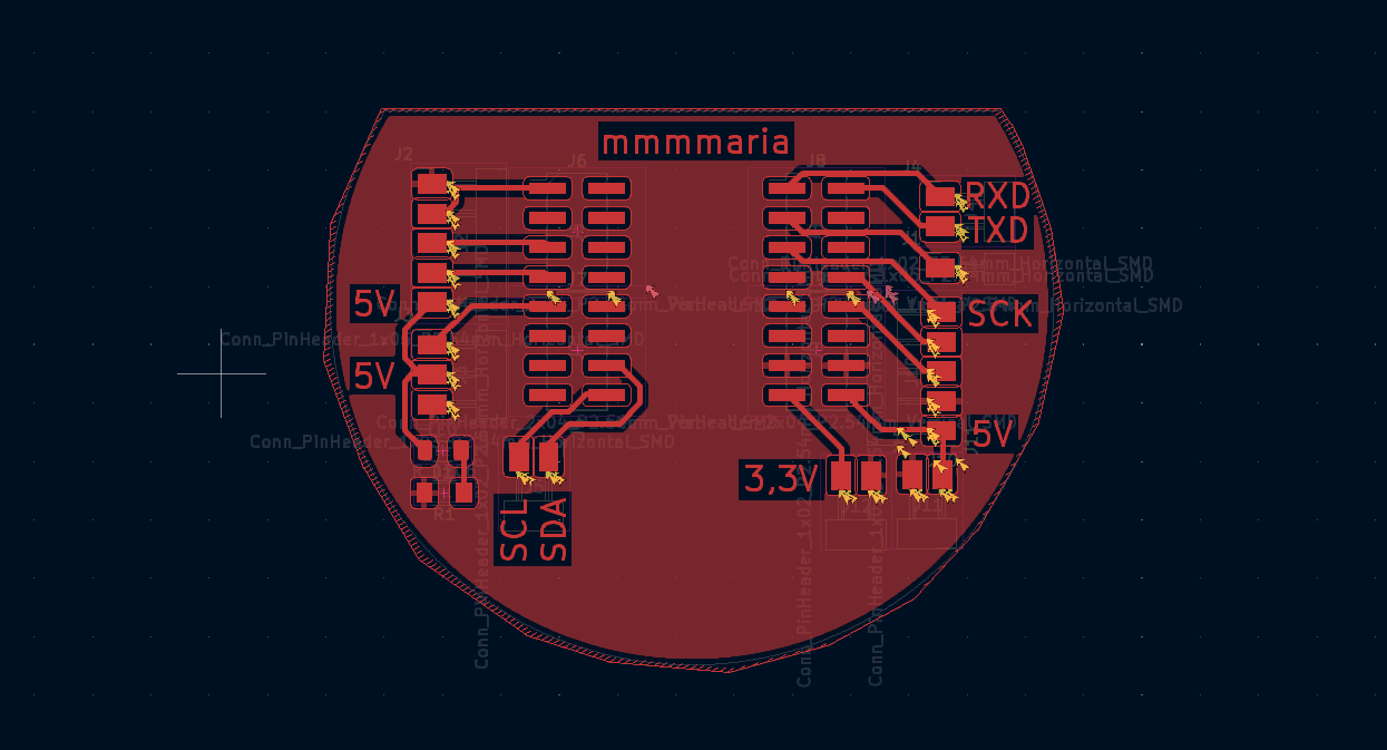
But besides that I located my icon on board. Changing it in such way, that I will be able to change shape of an icon.
As you can see in final result, I made my 2 sided board from 2 pieces, it was more convenient for me.
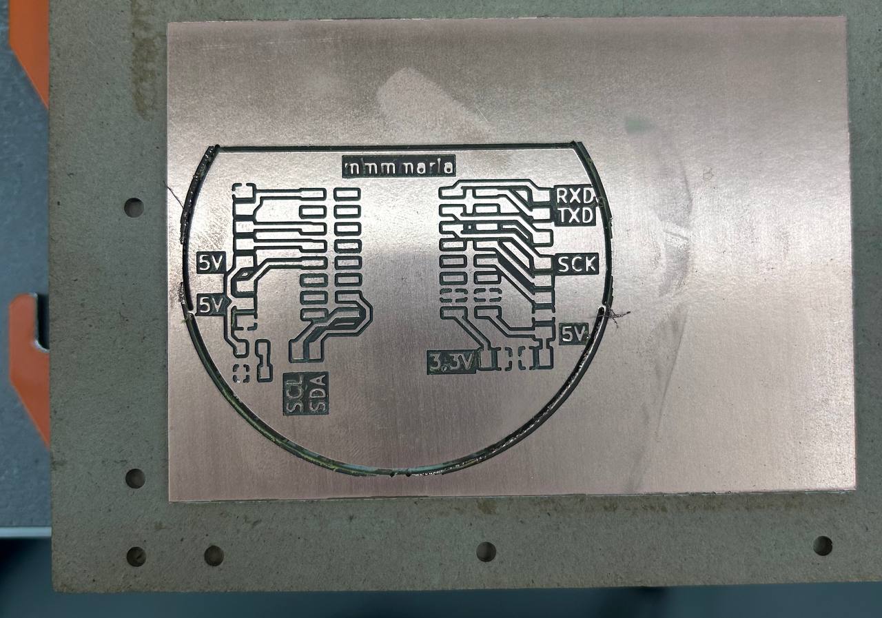
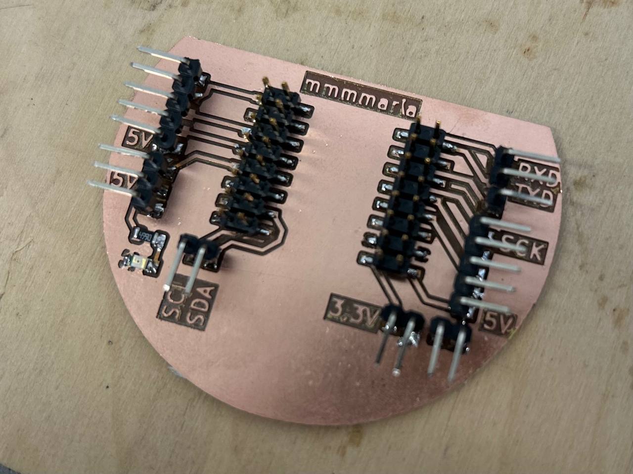
Board cutting and soldering
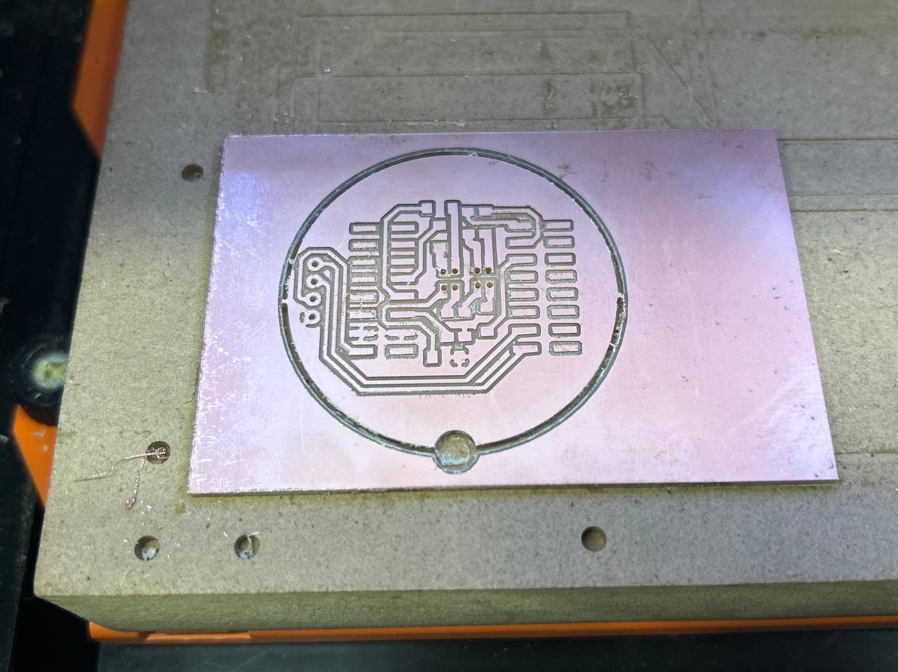
After I cut my first board.
Here is my final result.
And after finishing my first board soldering I handle to my 2nd board to be cut and soldered.
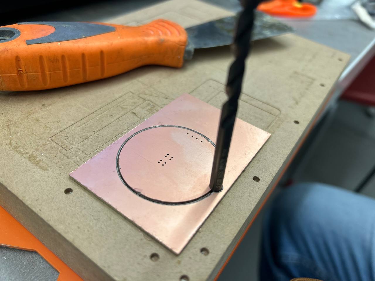
This circle I cut so that after rotating to the other side, I could easily find the right orientation.
For rotating it was also needed something rounded, so that I could fix the location of PCB.
One of the hardest parts was soldering connectors which had to be similar to my S2Mini modules footprints.
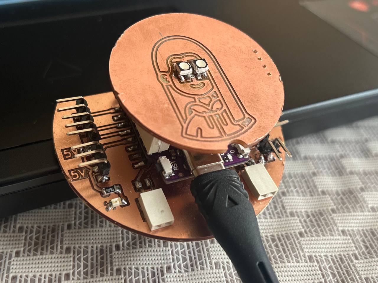
So after this hard part, there were another challenging thing, and it was soldering of RGBs for girls eyes.
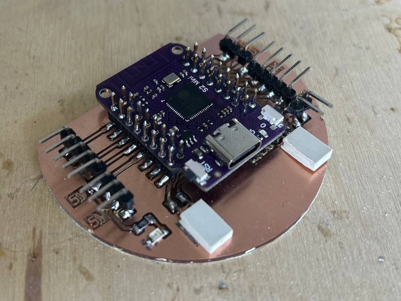
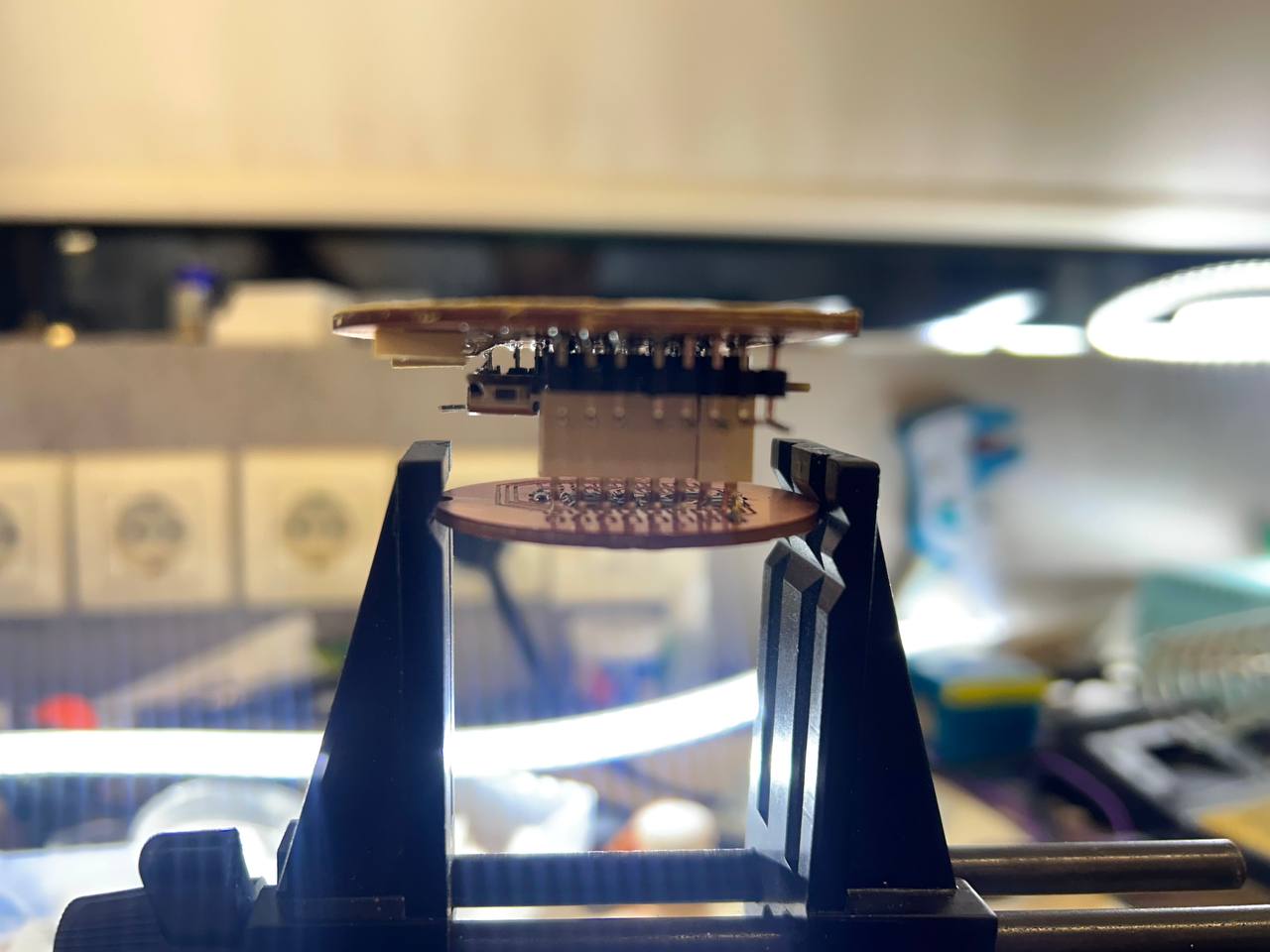
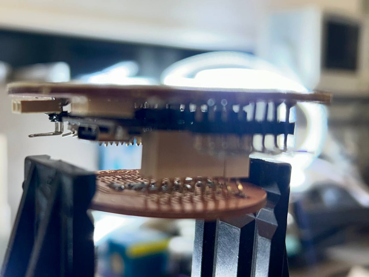
This is the very first result of putting together 2 boards.
The most challenging part of this boards production was soldering this to RGB LEDs. For later I will be more attentive to designing components in the way, so that it will be convenient for soldering after.
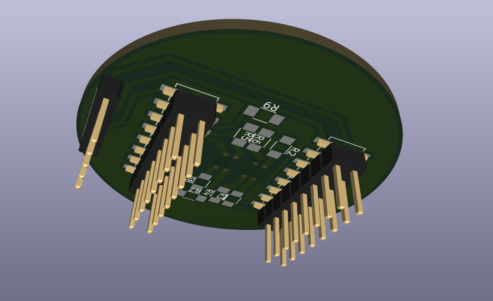
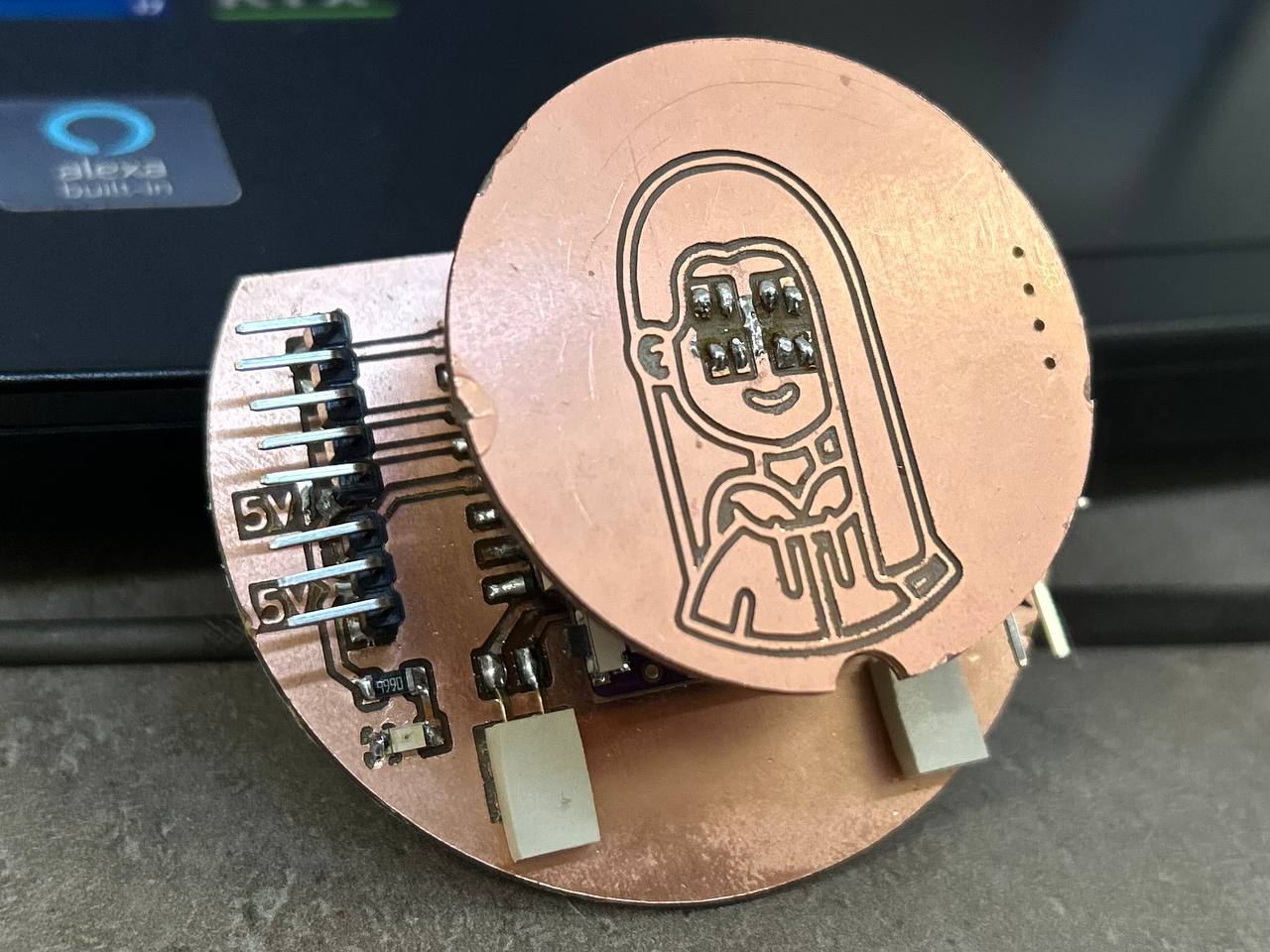
Final PCB Board View
I2C communication
While programming the microcontroller, I noticed some problems. Every time I entered the code, sometimes it was programmed, other times it wasn’t. So I managed only to program the LEDsin of the girl’s eyes, but didn’t take a photo.
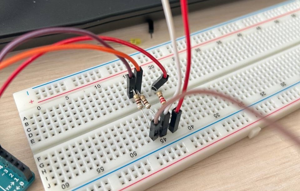
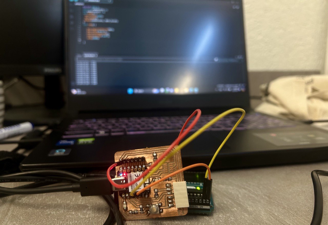
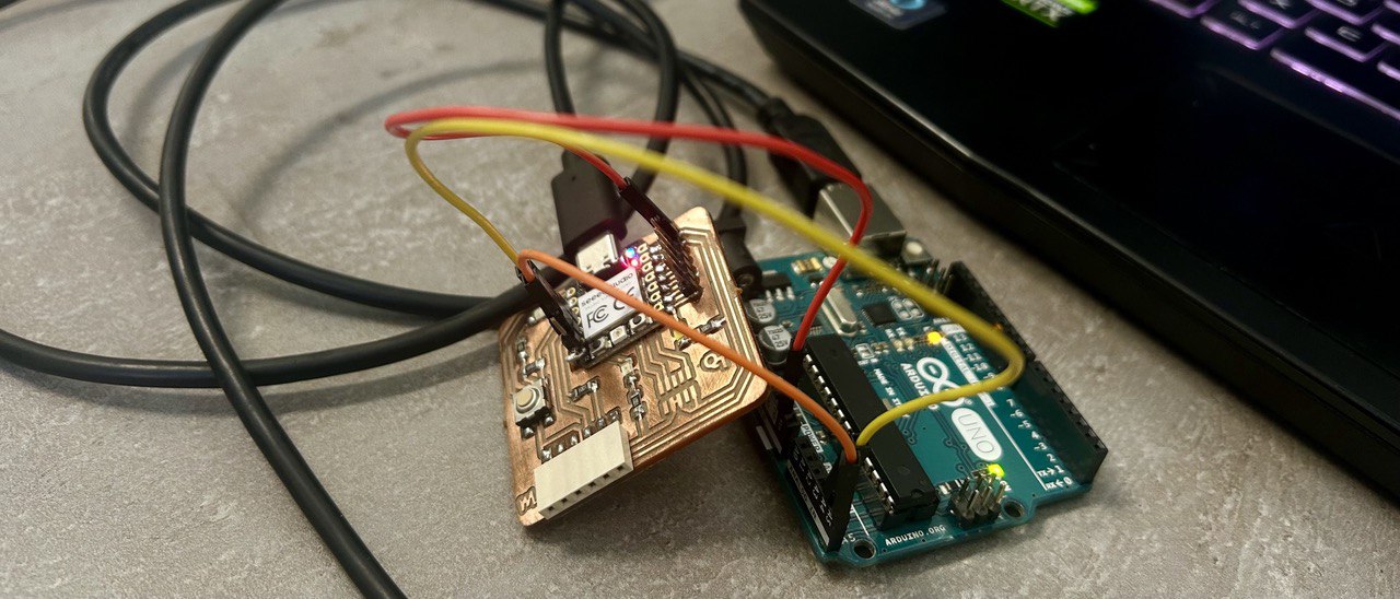
As I made sure that it is impossible to work with this module, I just took 2 other boards. One was Quentorres board the other one Arduino Uno. I used I2C communication which uses two wires for communication - SDA and SCL.
The primary board sends an address along with a read/write bit to communicate with the secondary board.
As I find a good website about I2C, you can read detailed about I2C there. So I2C is a serial communication protocol, so data is transferred bit by bit along a single wire (the SDA line).
SDA (Serial Data) – The line for the primary and secondary to send and receive data.
SCL (Serial Clock) – The line that carries the clock signal.
And for programming these boards Shushanik’s documentation helped a lot.
I took one primary code and one secondary.
I connected SDA, SCL and GND pins to each other.
Primary code looked like this:
#include <Wire.h>
const int endSwitchPin =3;
int endSwitchState = 0;
void setup() {
  Serial.begin(9600);
  Wire.begin();
 pinMode(endSwitchPin, INPUT_PULLUP);
}
void loop() {
    Wire.beginTransmission(0x9);
    Wire.write("On");
    Wire.endTransmission();
    Serial.println("sent");
    delay(1000);
    Wire.beginTransmission(0x9);
    Wire.write("Off");
    Wire.endTransmission();
    Serial.println("sent");
    delay(1000);
}
And secondary:
#include <Wire.h>
#define I2C_Secondary_ADDRESS 0x9
void setup() {
  Serial.begin(9600);
  Wire.begin(I2C_Secondary_ADDRESS);
  Wire.onReceive(receiveEvent);
  pinMode(1, OUTPUT);
}
void loop() {
}
void receiveEvent(int howMany) {
  String data = "";
  while (Wire.available()) {
    data += (char)Wire.read();
  }
  if (data.equals("On")) {
    digitalWrite(1, HIGH);
  }
  else if(data.equals("Off")) {
      digitalWrite(1, LOW);
    }
  Serial.println(data);
}
With this code, I made it so that when my Quentorres board receives the “On”, it turns on the LED.
Conclusion
This week was extensive. I spent a lot of time designing, cutting and soldering my board. But apart from that, there was little time left to perform the actual task, to create communication between 2 board.
I managed to complete the task and I am satisfied with that.