8. Electronics Design
This week I used an EDA tool (KiCad) to design a development board to interact and communicate with an embedded microcontroller(AtTiny 1614). I used this week’s assignment for making my previous week’s chandelier PCB board.
Group Assignment
As part of a group assignment we explored new topics:
We talked about semiconductors. There are negative and positive types of semiconductors.
We talked about the diode. As an example - LED is a diode - light-emitting diode (a semiconductor diode which glows when a voltage is applied). A diode has direction. When you put the diode in the right direction, it allows current to flow through it. If you put it in the opposite direction, it does not allow current to pass through. Diode has various applications in electronics.
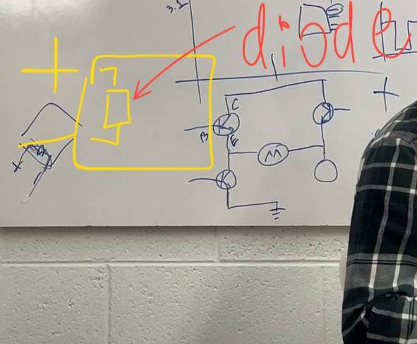
Most of the time, the diode is placed in the places where security is needed. They put such a diode, for example, that if you connect it correctly, current will pass through it, but if you make a mistake and connect the current, the diode will not allow current to pass and the plate will not light up. It happens that they get confused and connect the wires incorrectly, because of which everything breaks, but when you put a diode, the diode provides you with that.
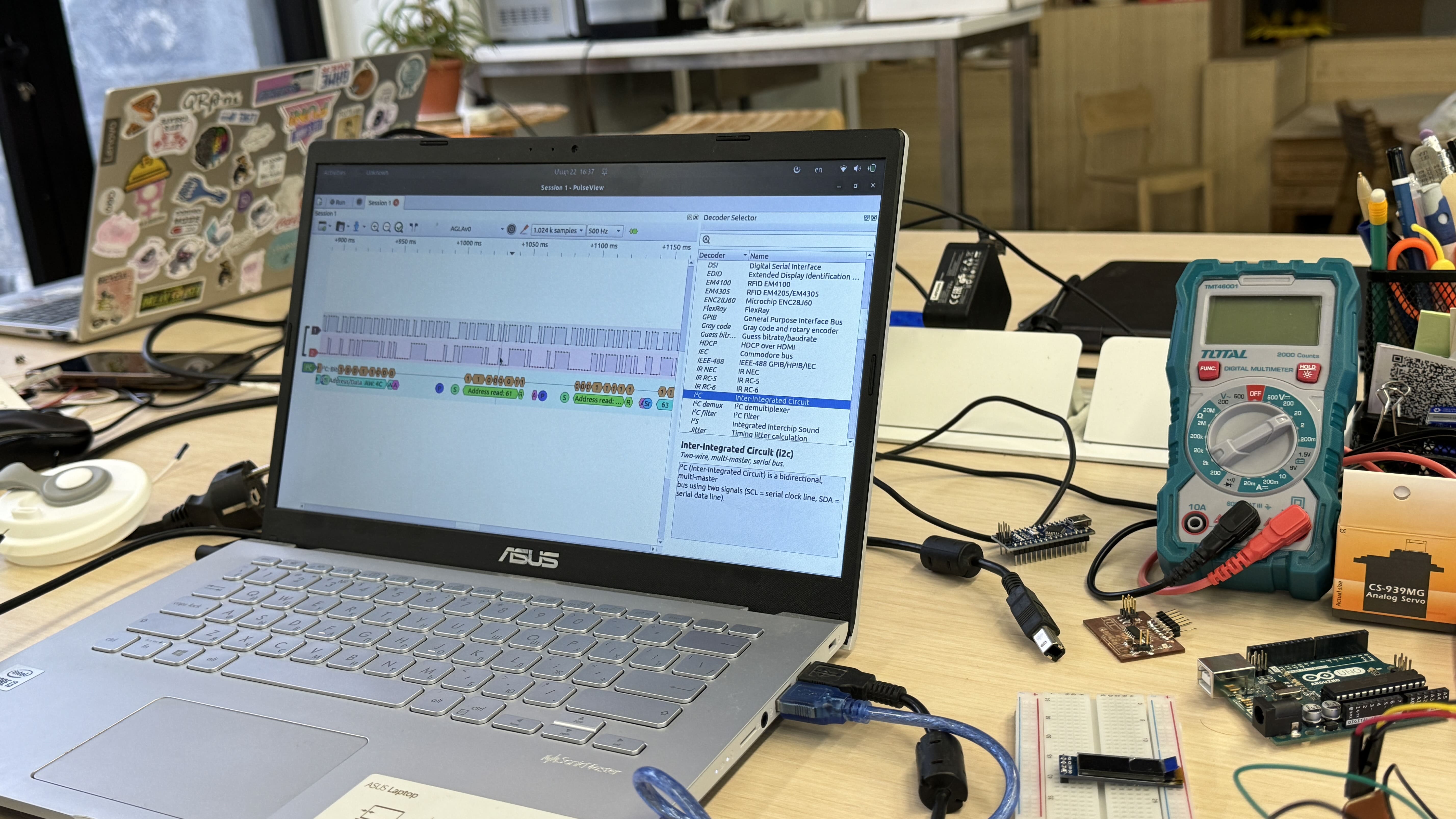
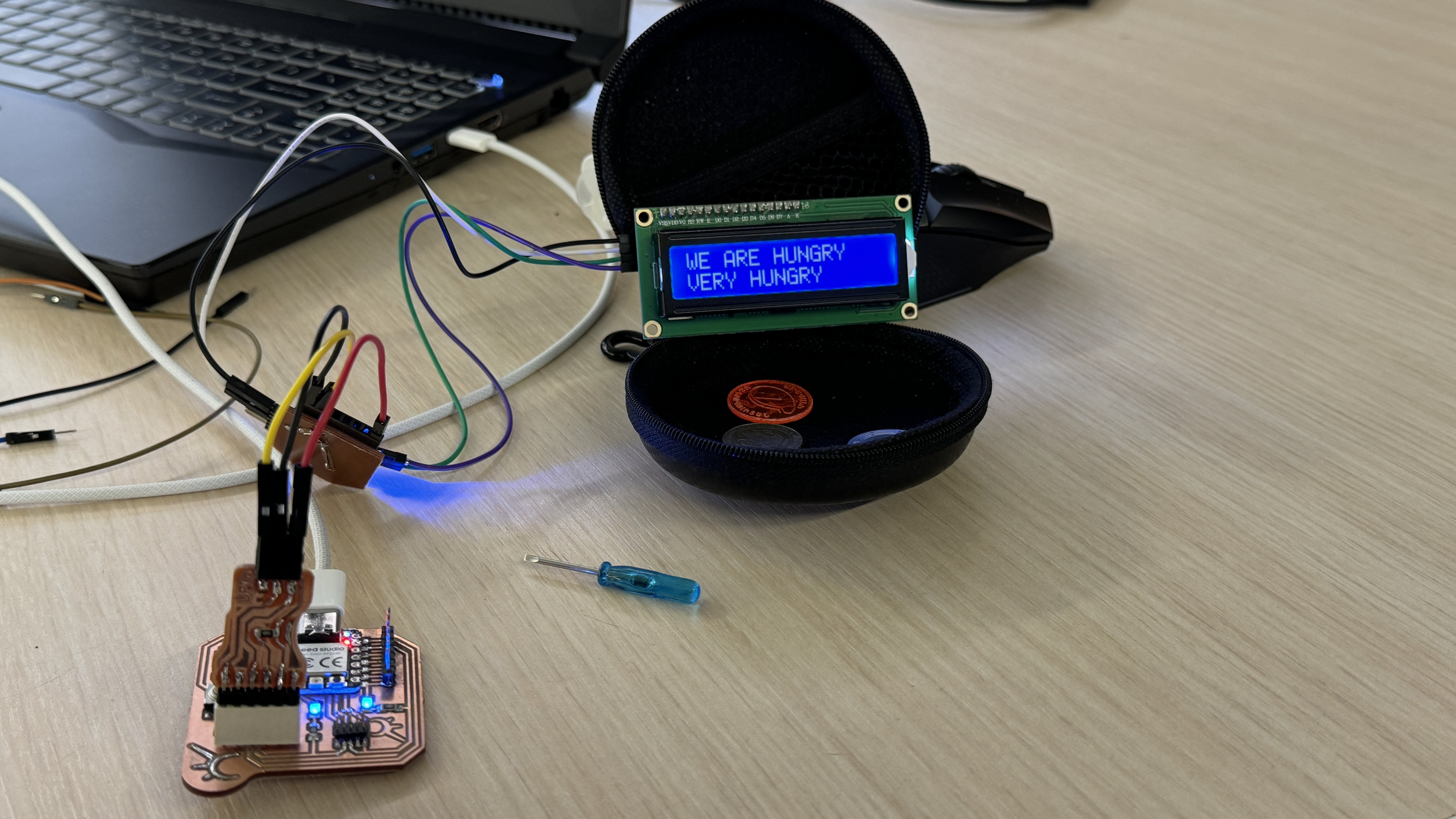
Also we made a logic analyzer using Arduino and read the I²C signal from Areg’s microcontroller to the LCD display. A logic analyzer is a tool for taking and analyzing digital signals. It allows to visualize the attitude of digital signals (such as I²C, SPI, UART, etc.) over time.
I²C is a two-wire serial communication protocol that enables various devices to communicate with one another using a shared bus.
My PCB board
At first for designing my own board, I decided to plan and understand what my board has to do. As it is for my chandelier, and my chandelier has to have a stepper motor, driver and sensor-I started from sketching my board on paper and drawing components and wires, so I could imagine what will I need.
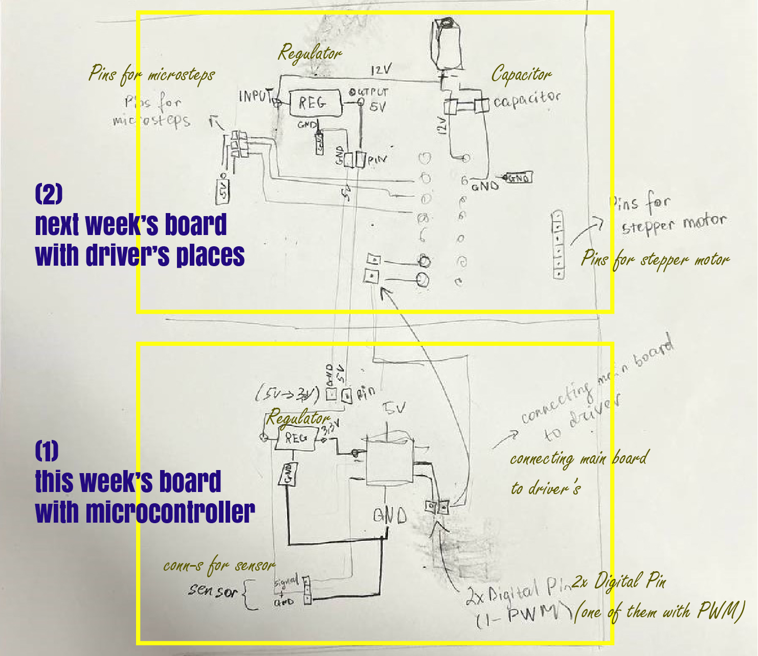
After finding out what can I make and do, I started my real journey in designing PCB.
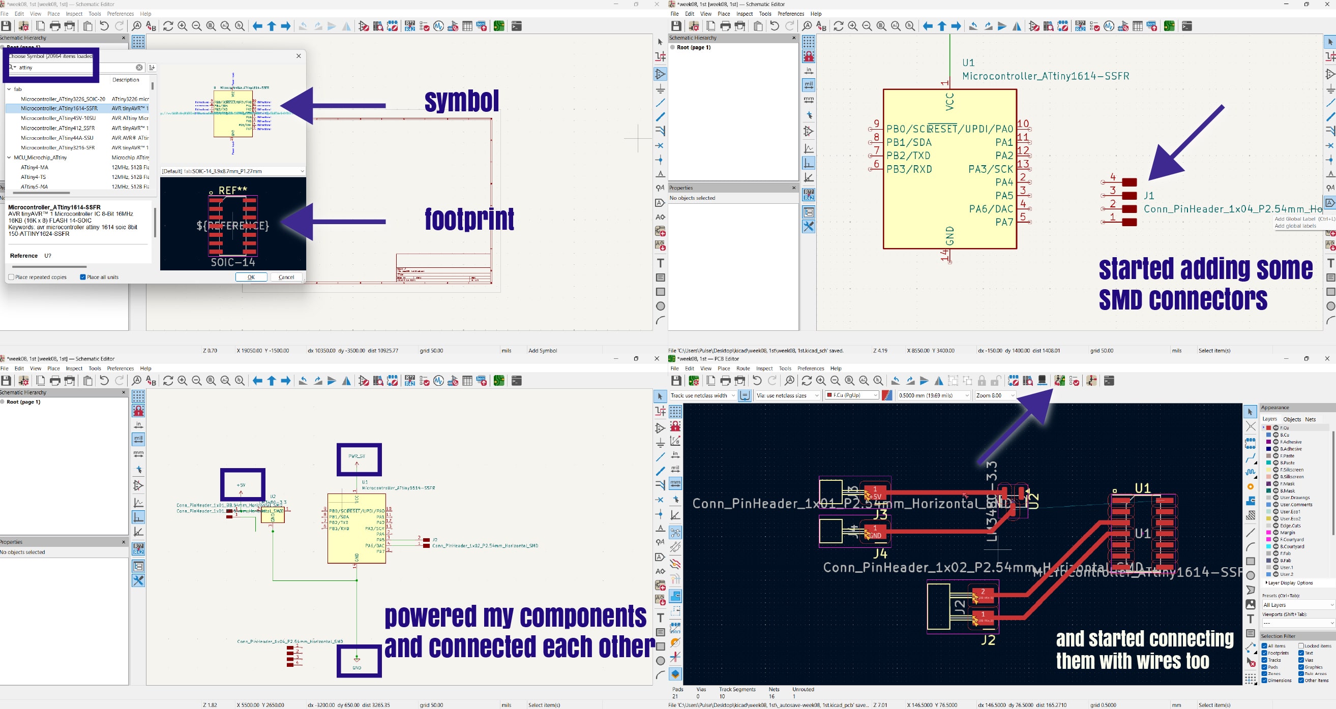
At first I put microcontroller - AtTiny1614, added his footprints and after started adding other components with their symbols and footprints.
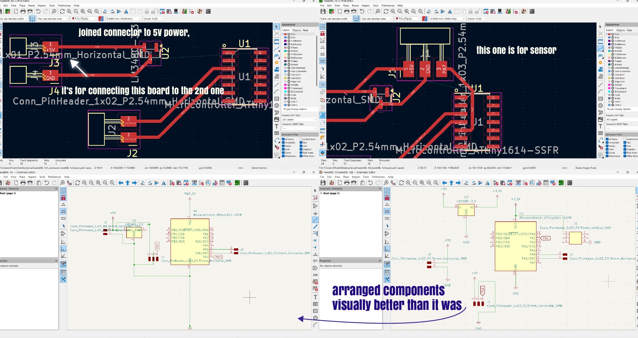
Designing by KiCad
In pictures below I introduced process of designing my PCB.
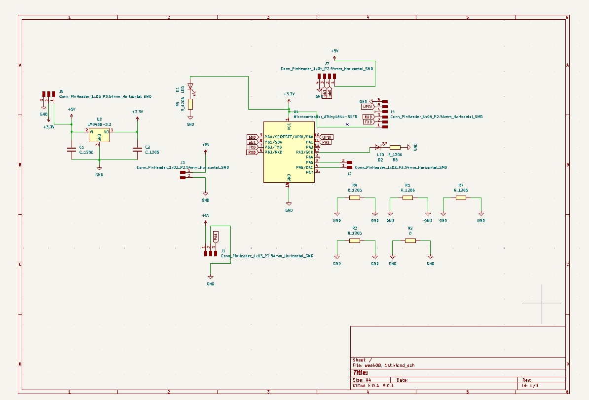
Here is my final board scheme.
After I corrected all components on my PCB too, changes wires and connected them with maximum user-friendly layout. Also I added drills, so that I could paste it on my chandelier.
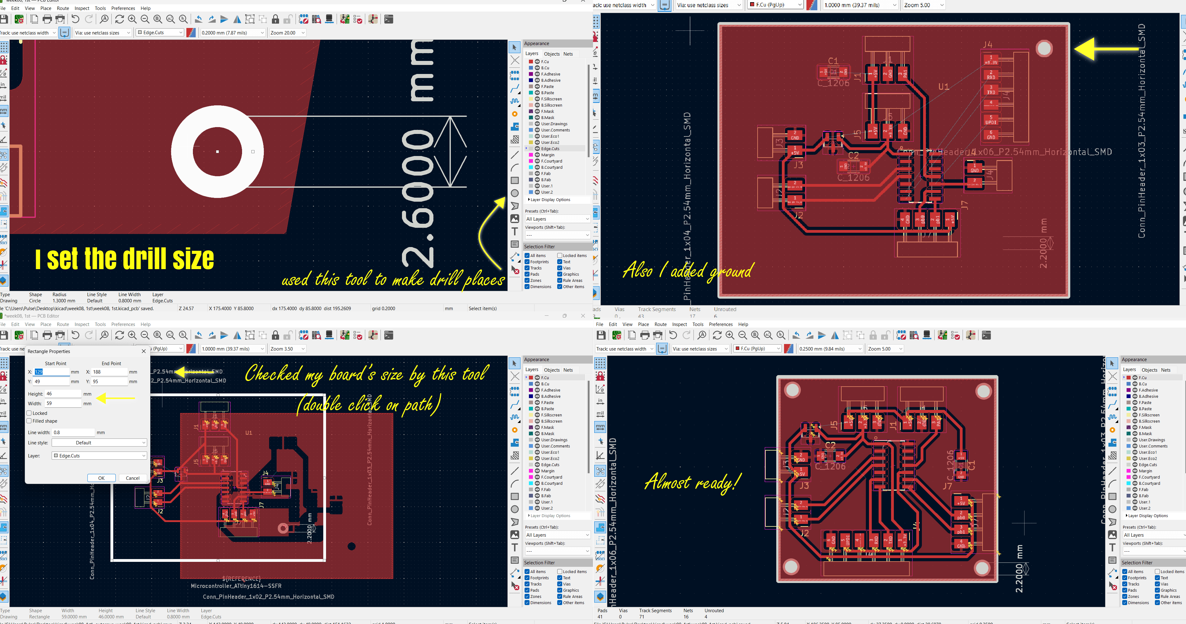
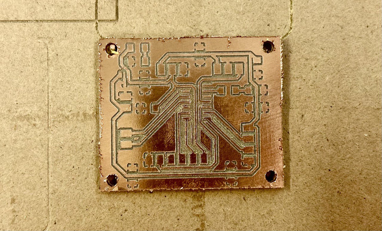
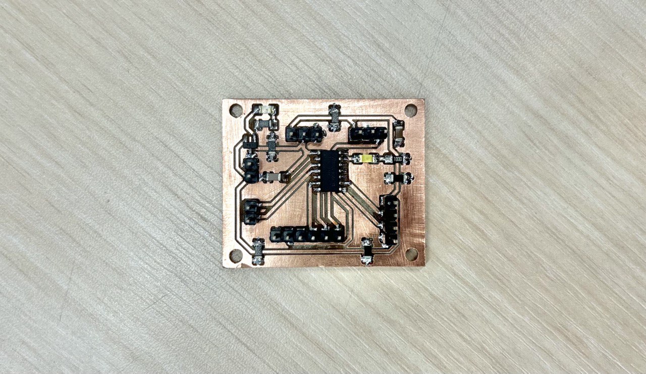
And here is the final PCB design. Sizes of it - 43mm x 35mm
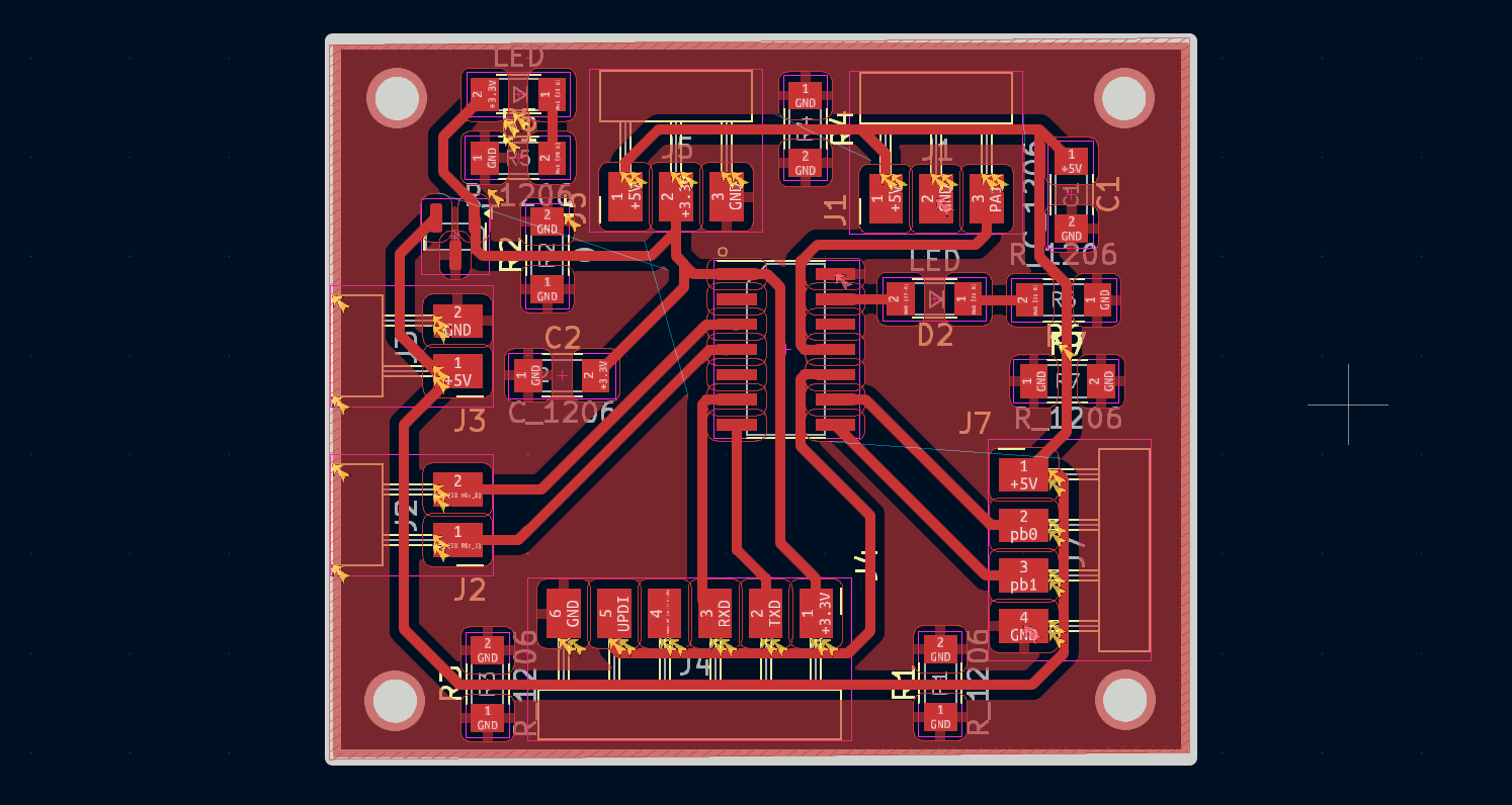
You can notice on my board 5x 0 Ohm Resistors-there are for connecting GND in places where it’s isolated. - RES 0 OHM JUMP SMD 1206
Exporting as SVG
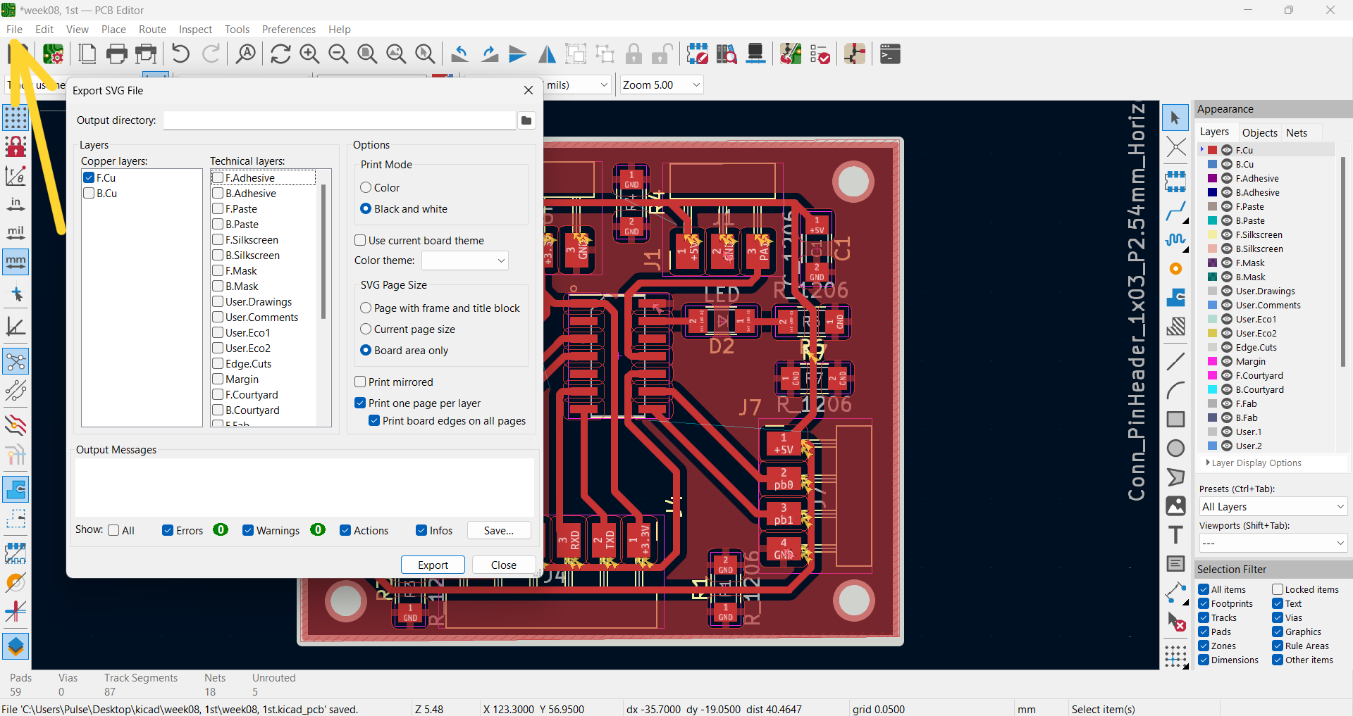
In this page I checked all components, wires, connections and exported it as SVG file. (Files>Export>SVG) After that the program will open this window. For saving traces I chose this type below with F.cu layer
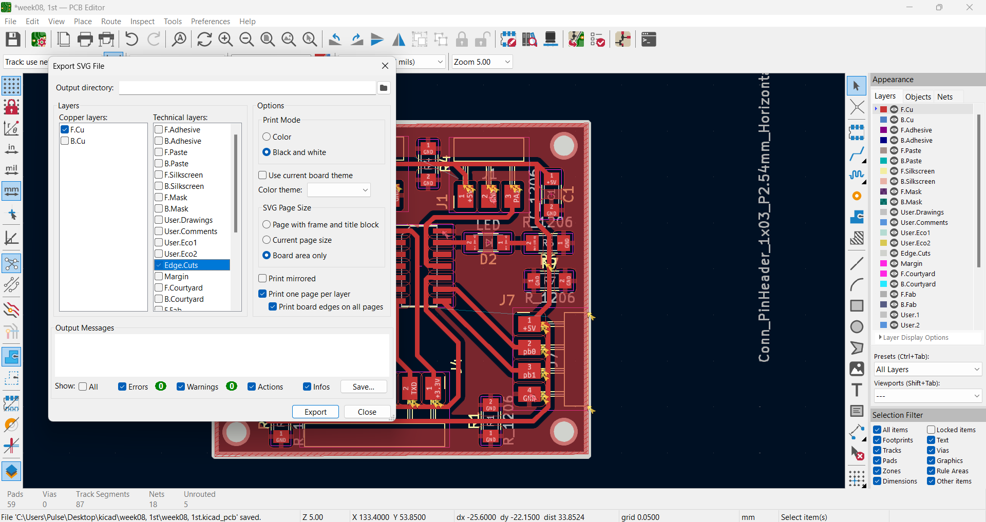
And for outline and drills I chose Edge.Cuts layer.
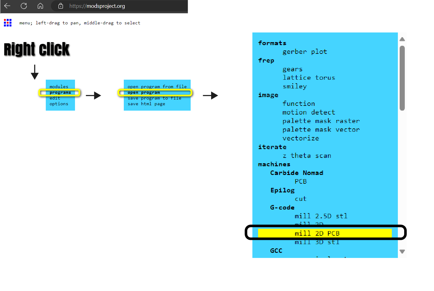
G-Code Generation
After designing by KiCad it’s time to generate the G-Code for PCB and send it for cutting.
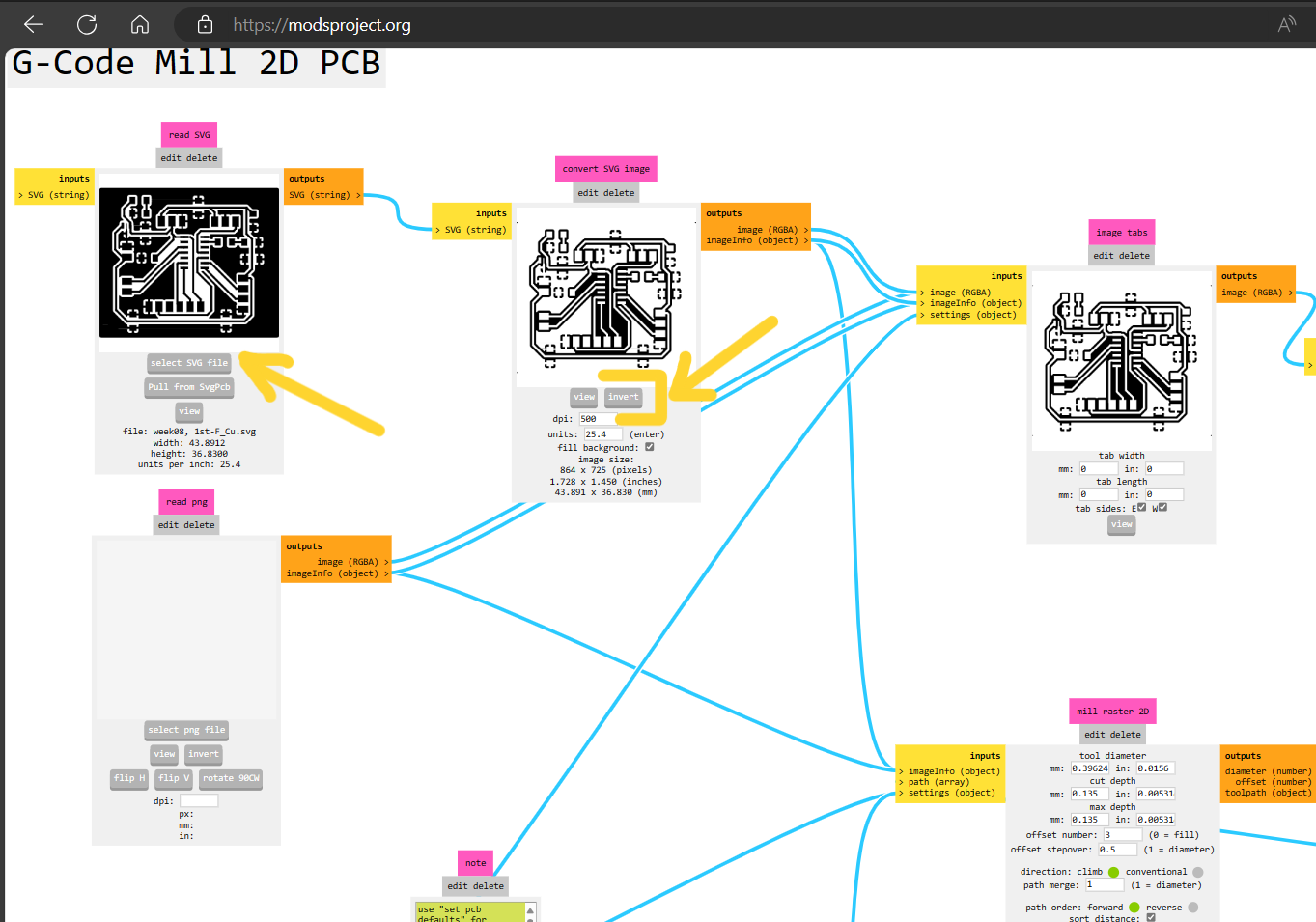
On my Electronics production Week I already documented how to generate a G-Code from PNG, but this week I generated it using SVG file. There were a little bit of difference.
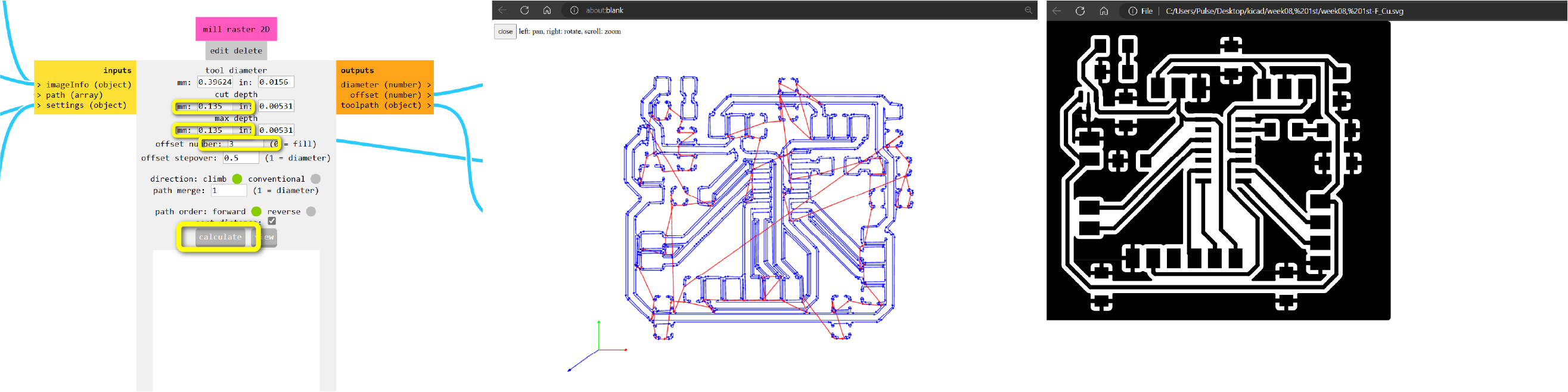
Isolate Traces 1/64
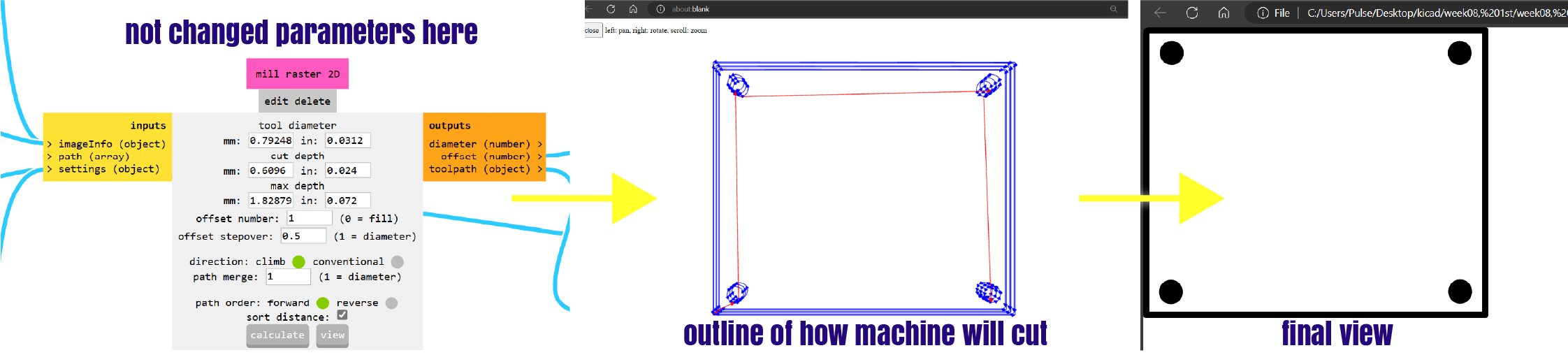
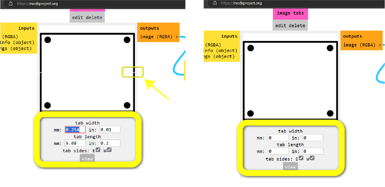
First time that I generated my G-Code, I noticed that my outline’s layout has some weird tabs in 2 sides, and by changing it’s width and length I managed to make my board without tabs, as I stick with tape.
G-Code for Traces >>
Mill Outline 1/32
After that my files were ready I started process of preparing to cut.
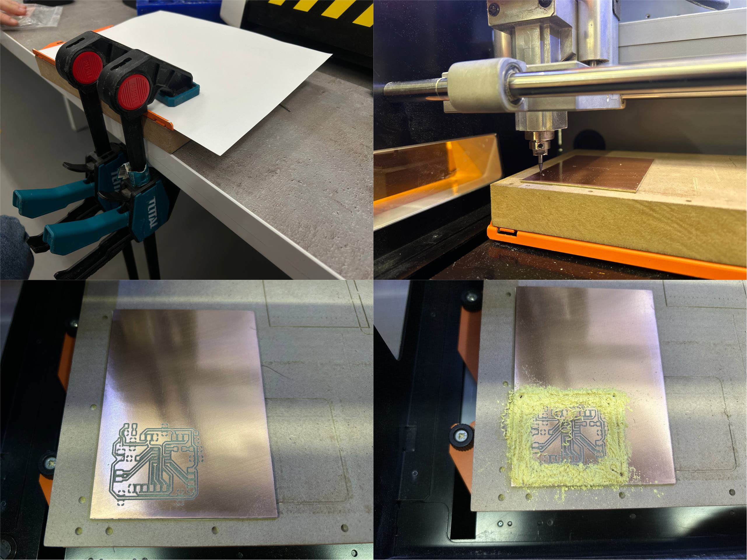
PCB Board Cutting
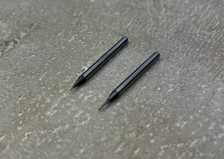
These 2 mills I used to trace and outline my board. Left is for tracing and right is for cutting.
I sticked my boards below part to tracing surface and pressed it, so that it won’t torn off.
Set the mill for tracing. And after changing it got the whole board cut.
Soldering
After sanding my board I started soldering process.
Soldering process was already known by me from previous weeks.
At first I soldered all 9 Ohm Resistors, then 2 other resistors and LED - one for always being enabled(green) and the other one is white-for coding and checking if my board and microcontroller are working well.
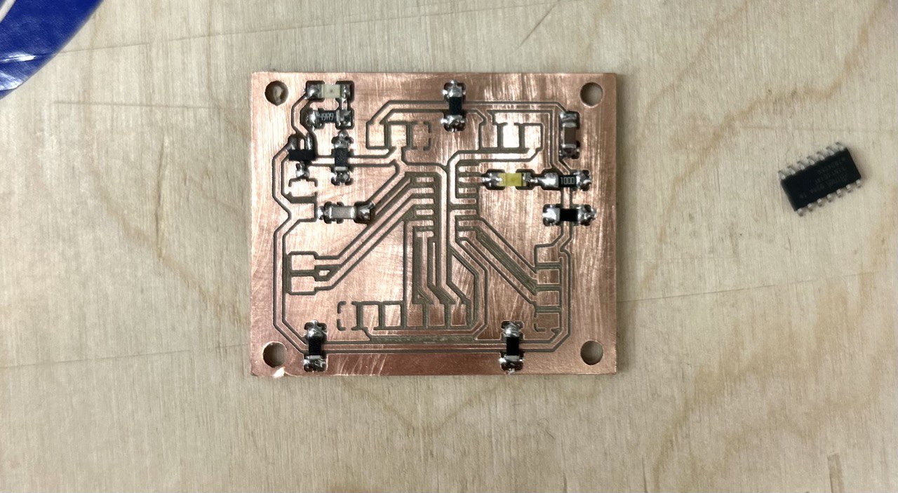
And after added microcontroller and connectors.
Programming
void setup() {
  // initialize digital pin LED_BUILTIN as an output.
  pinMode(10, OUTPUT);
}
// the loop function runs over and over again forever
void loop() {
  digitalWrite(10, HIGH);  // turn the LED on (HIGH is the voltage level)
  delay(20);                      // wait for a second
  digitalWrite(10, LOW);   // turn the LED off by making the voltage LOW
  delay(20);                      // wait for a second
}
Blinking LED, Cinnecting
For connecting all this wires and connect my microcontroller to Arduino Maxime’s documentation helped me a lot.
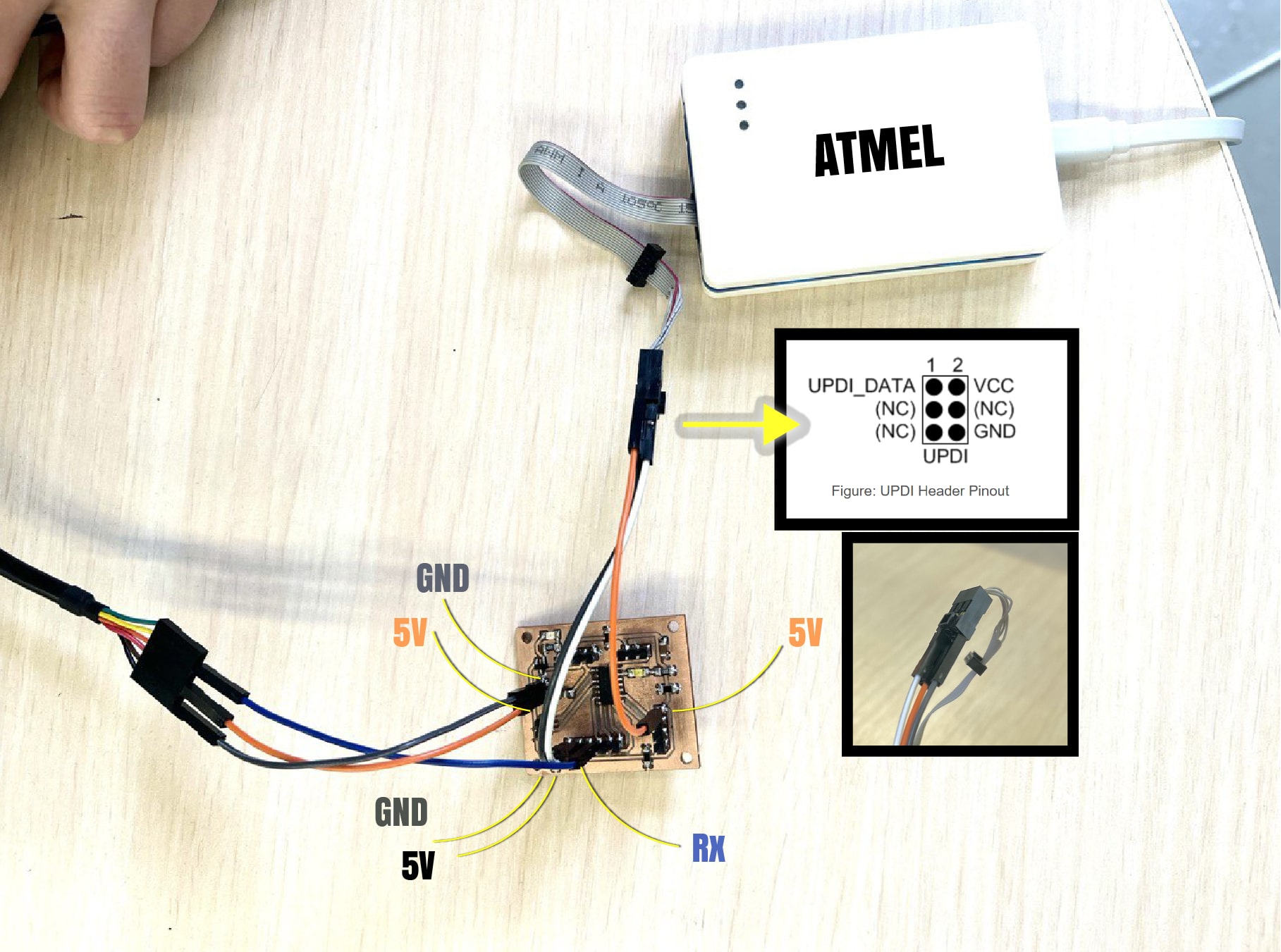
So in this photo you can see how I connected my AT Tiny 1614 microcontroller to Atmel-ICE and another wire, by which I connected Rx, GND and 5v.
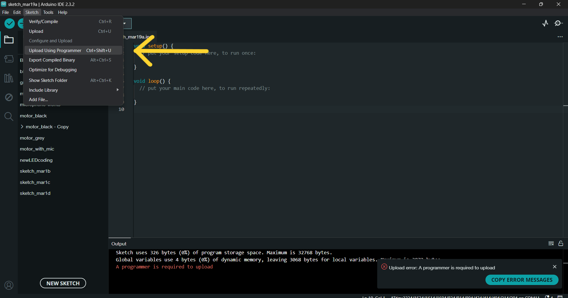
I programmed my micro by Atmel-ICE.
And this is the way you can do it in Arduino IDE.
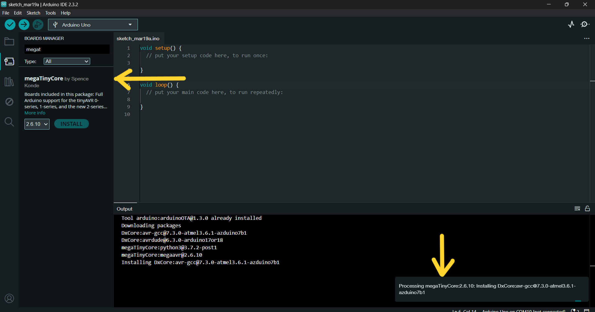
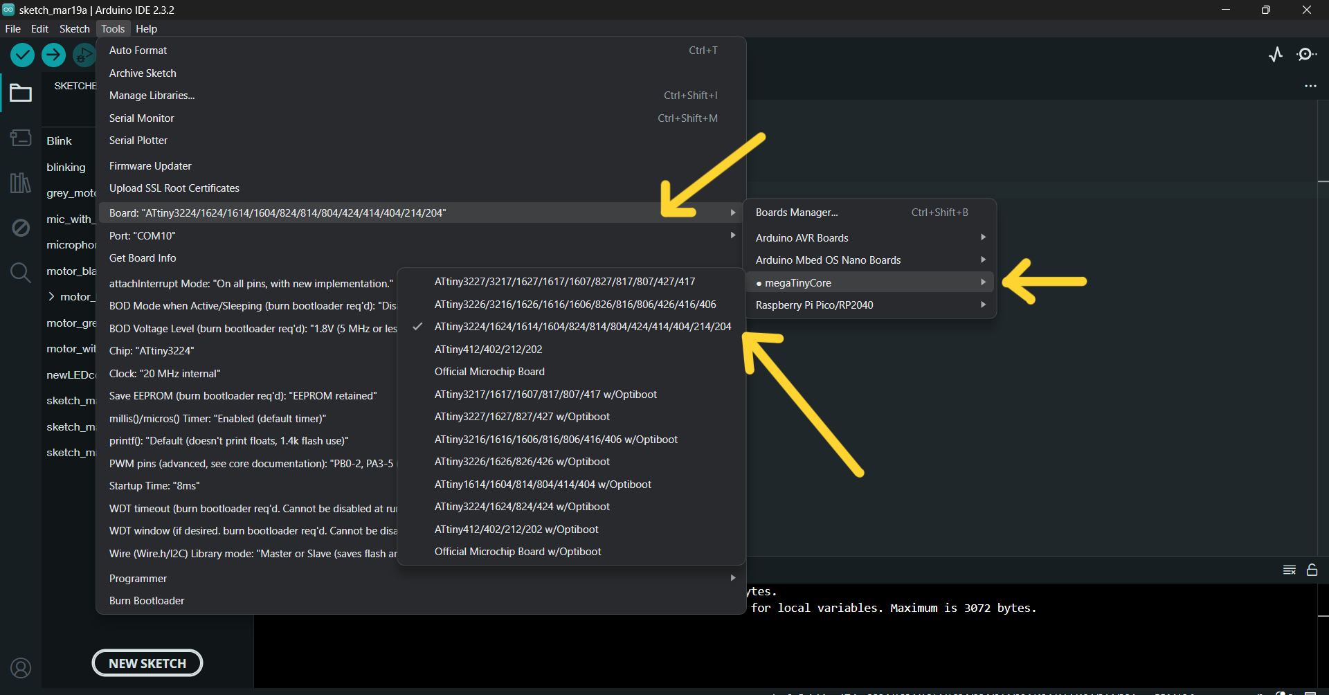
Go to Tools >> Board >> Additional Boards Manager >>
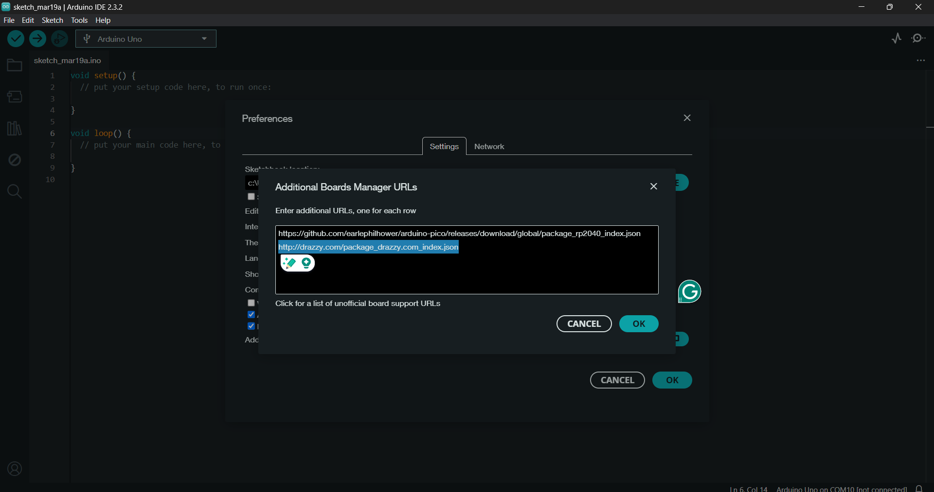
Paste the URL
http://drazzy.com/package_drazzy.com_index.json
which is installing the package for the ATTINY1614 (megaTinyCore from Spence Konde).
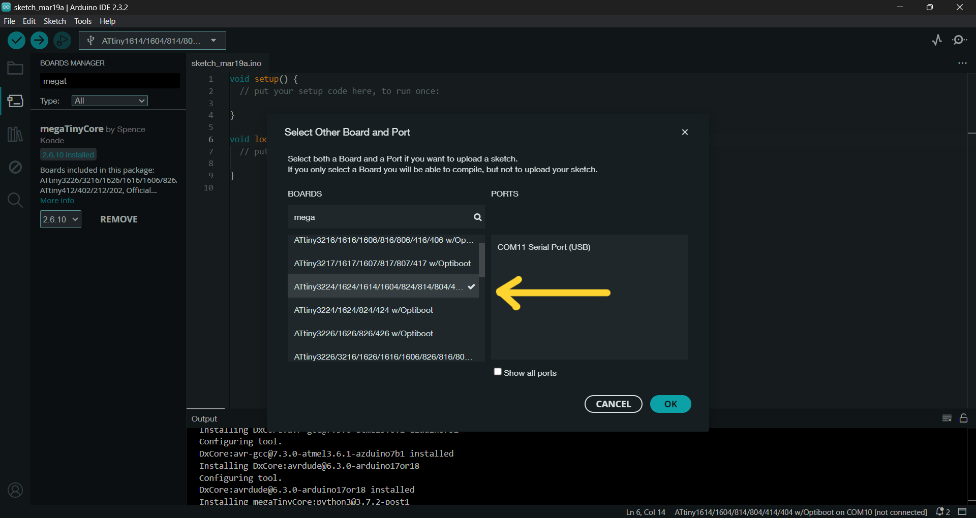
And as I read in Maxime’s documentation that he didn’t able to upload the code because AT TINY1614 with Optiboot, which didn’t support upload with UPDI, I chose >>
That’s it!
Conclusion
This cool week I ended having a functional PCB board which I will use in my final project - for my chandelier. I designed there all that I needed, tidier, small sizes. Also I used Atmel-ICE for programming my AtTiny microcontroller.
By making this PCB board I realized that I have some understanding on what I’m doing, what I need to design first, to think about and etc. So I learned a lot and improved my skills in soldering and designing board.