4. Electronics production
This week I’ve got acquainted with operation of a microcontroller circuit boards, circuit board design, part of electronics Design.
PCB Board and Common Components
Exploring and learning about PCB (Printed Circuit Board) boards are like electronic puzzles, with different pieces (components) that fit together to make things work.
Learning about PCBs also involves knowing how they’re made. They’re like electronic sandwiches, with layers of materials sandwiched together to create pathways for electricity to flow.
### PCB, the process of cutting PCBs using CNC machines.
By asking ChatGPT I mentioned some information about PCBs below:
### Understanding PCB Components
What PCBs are, and some of the common components, including microcontrollers, serial communication devices and etc.
PCB is a flat board made of non-conductive material with copper foil’s thin layer etched onto their surface.
They work as a platform for connecting electronic components to create functional circuits. PCBs provide electrical pathways (traces) for signals to travel between components, ensuring proper functioning of electronic devices.
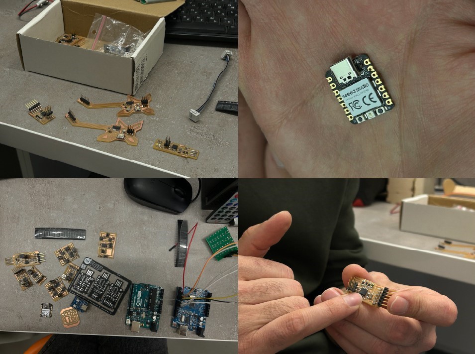
Common Components Found on PCBs
Microcontrollers: These are small computers integrated onto a single chip. They function as an intellectual capacity of many electronic devices, controlling their operation and processing data.
Serial Communication Devices: Devices like UART (Universal Asynchronous Receiver-Transmitter) chips provide serial communication between electronic components. They translate parallel data from microcontrollers into serial data for transmission over communication lines.
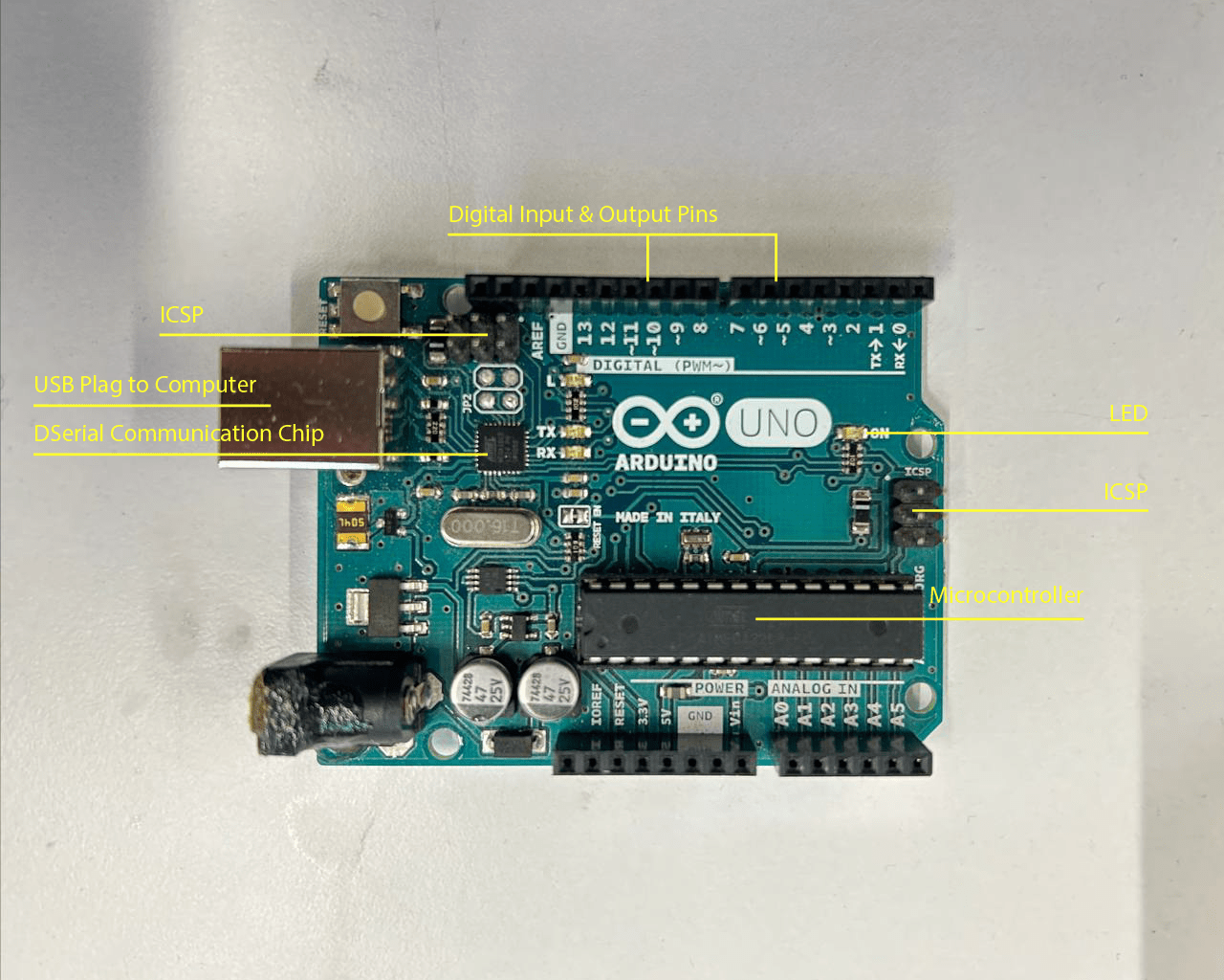
Microcontrollers are structured circuits that include a processor core, memory, and input/output peripherals. They execute instructions and control the operation of electronic devices based on programmed logic. Microcontrollers are used in a wide range of applications, including embedded systems, devices, robotics, and consumer electronics. - For example, Arduino Uno is a common microcontroller board used for prototyping. It has an ATmega328P microcontroller.
Serial communication devices assist data transmission between electronic components through serial protocols. They convert parallel data from microcontrollers into serial data rivers and vice versa, enabling effective communication over serial interfaces. Serial communication devices are commonly applied in various applications, including communication between microcontrollers, interacting with sensors and actuators, and connecting peripherals to computers.
Resistors: They are like tiny barriers for electricity. They control how much electricity flows in a circuit.
Capacitors: They help flatten electricity flow and can store energy temporarily. Besides that, capacitors reduce or wipe out noise.
Diodes: They let electricity flow one way but block it in the other way.
LEDs (Light-Emitting Diodes): They are often applied as indicator lights in electronic devices.
Connectors: They are used to connect different parts of circuit together.
 Also, as a part of group assignment
Group Assignment
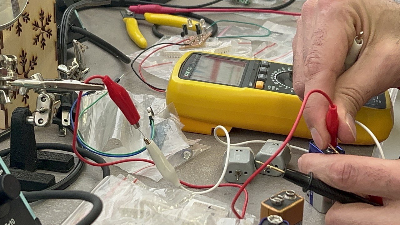
During the introduction, as part of a group assignment we also tried to put into practice what we talked about, and thus by taking wires with high noise/voltage, we tried to reduce the noise by using capacitor: which worked for us. By taking capacitors of different power, we obtained different degrees of noise reduction or even elimination process by oscilloscope. 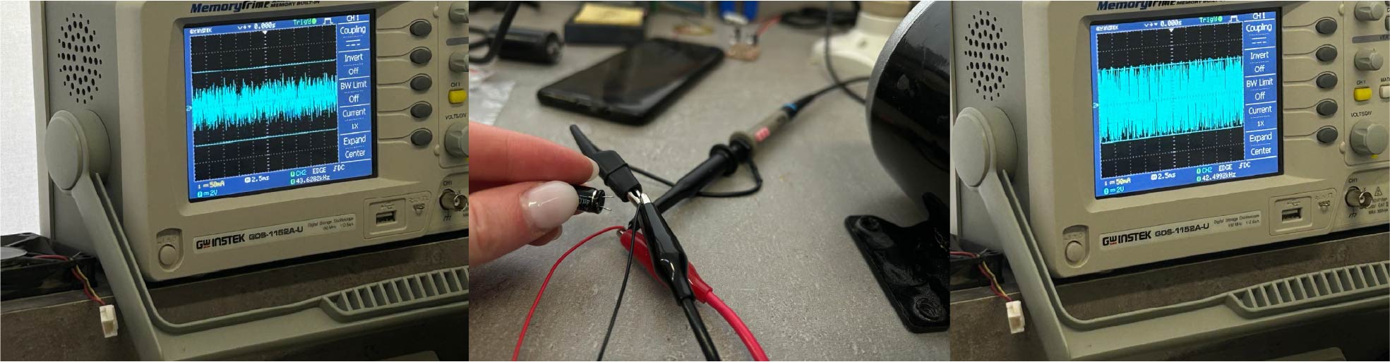
An oscilloscope helps to visualize electrical signals. It’s like an electronic microscope that lets you see how electricity changes over time.
The screen of an oscilloscope commonly looks similar to graph, with a horizontal axis - representing time and a vertical axis - representing voltage. When you look at the screen, you can see how the voltage of the signal goes up and down over time. This helps you understand what’s happening in your circuit or with your electrical signal.
We tried to burn some not dangerous components, to see how it works, what we do, that its burning.
Quentorres PCB
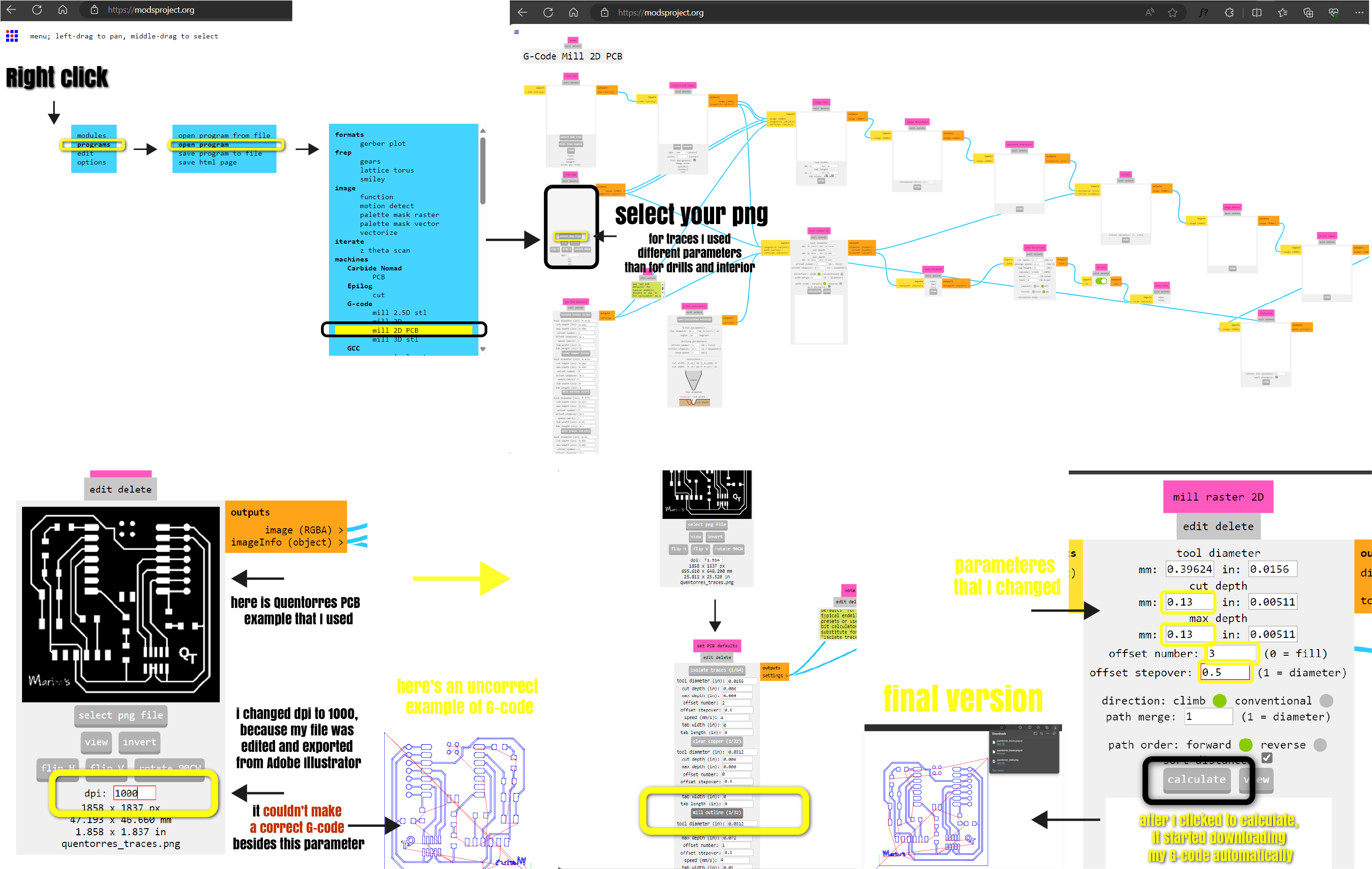
For making G-code I used Modsproject.
Here is how I made it:
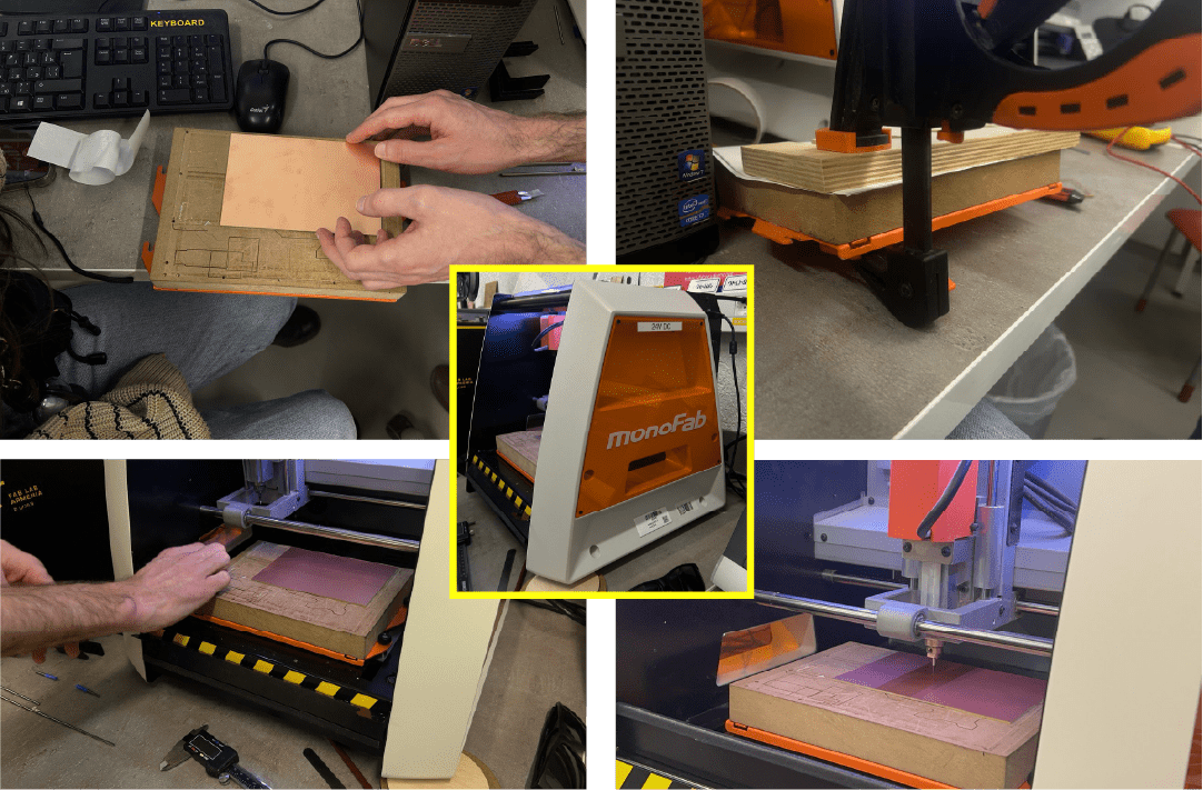
PCB Board manufacturing
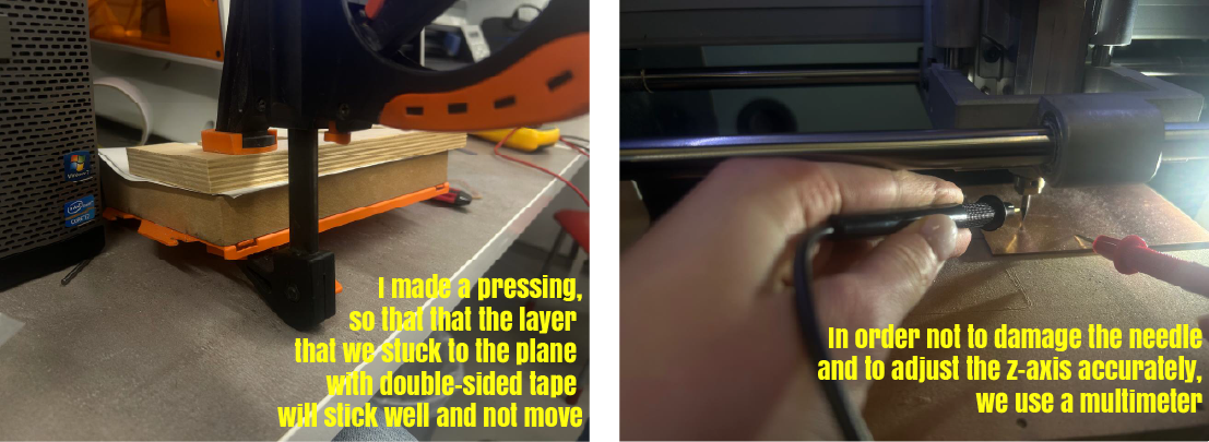
We cut our PCB boards by Roland MonoFab SRM-20. Before cutting as part of group assignment we got acquainted with needles-tried to change them, also with working surface, interface of software.
Soldering components on PCB Board
Also we got acquainted with “what soldering is”.
For my previous week assignment I already had a smaaaall experience in soldering.
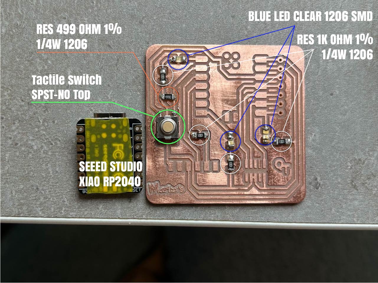
Useful liks: - OMRON SWITCH, SPST-NO Datasheet - Green LED - Seeed XIAO RP2040 RGB LED
In designing our PCB example that we already had, we used 2 types of resistors which you can see in photo. Also we used a switch, LEDs. For knowing component’s positive and negative sides we used a multimeter. As you can see in photo below - using this equipment I tried the LED and made sure that it works.
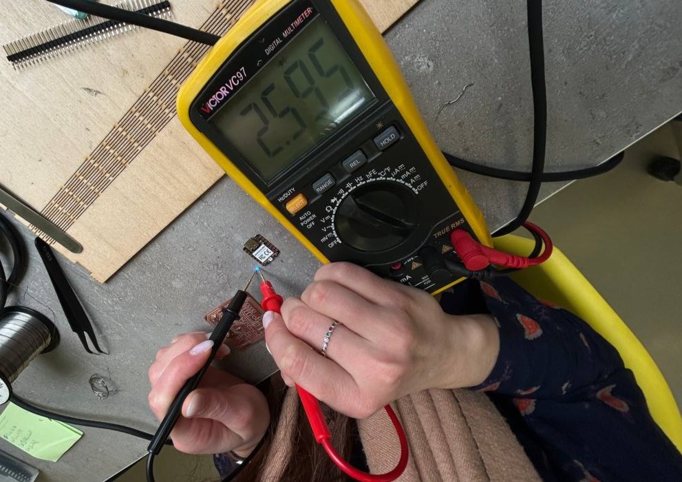
After trying every component, I was soldering them in board and trying multimeter on board (does it work, or not).
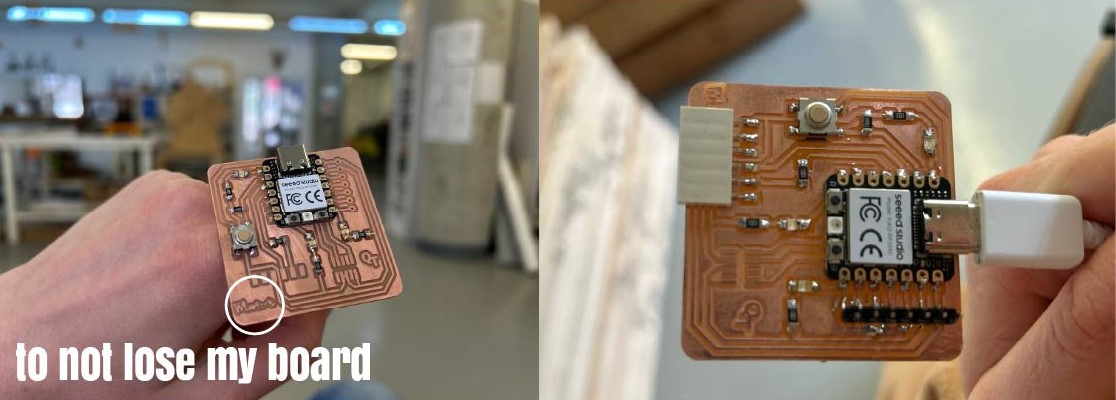
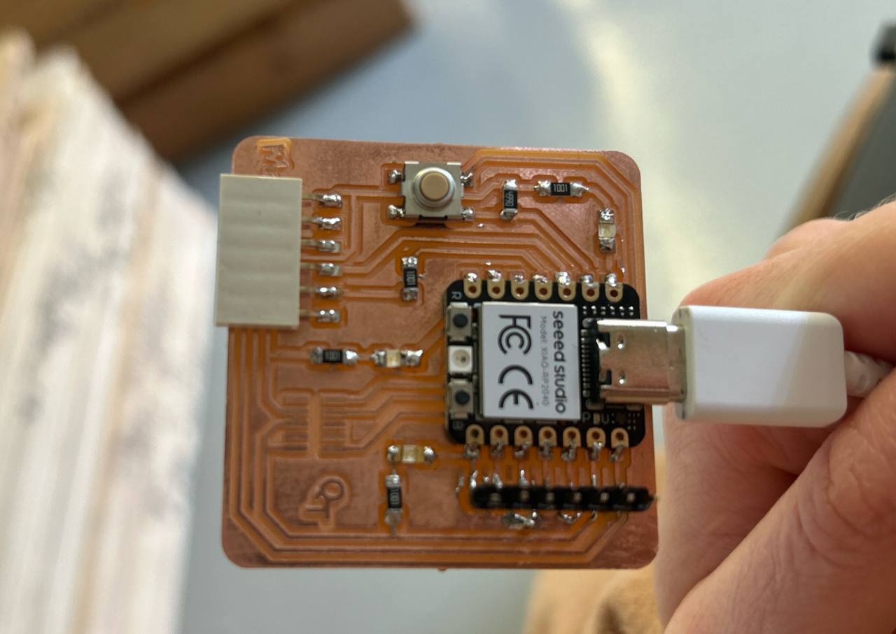
So after my board was soldered as needed and all was working, I switched it to my notebook.
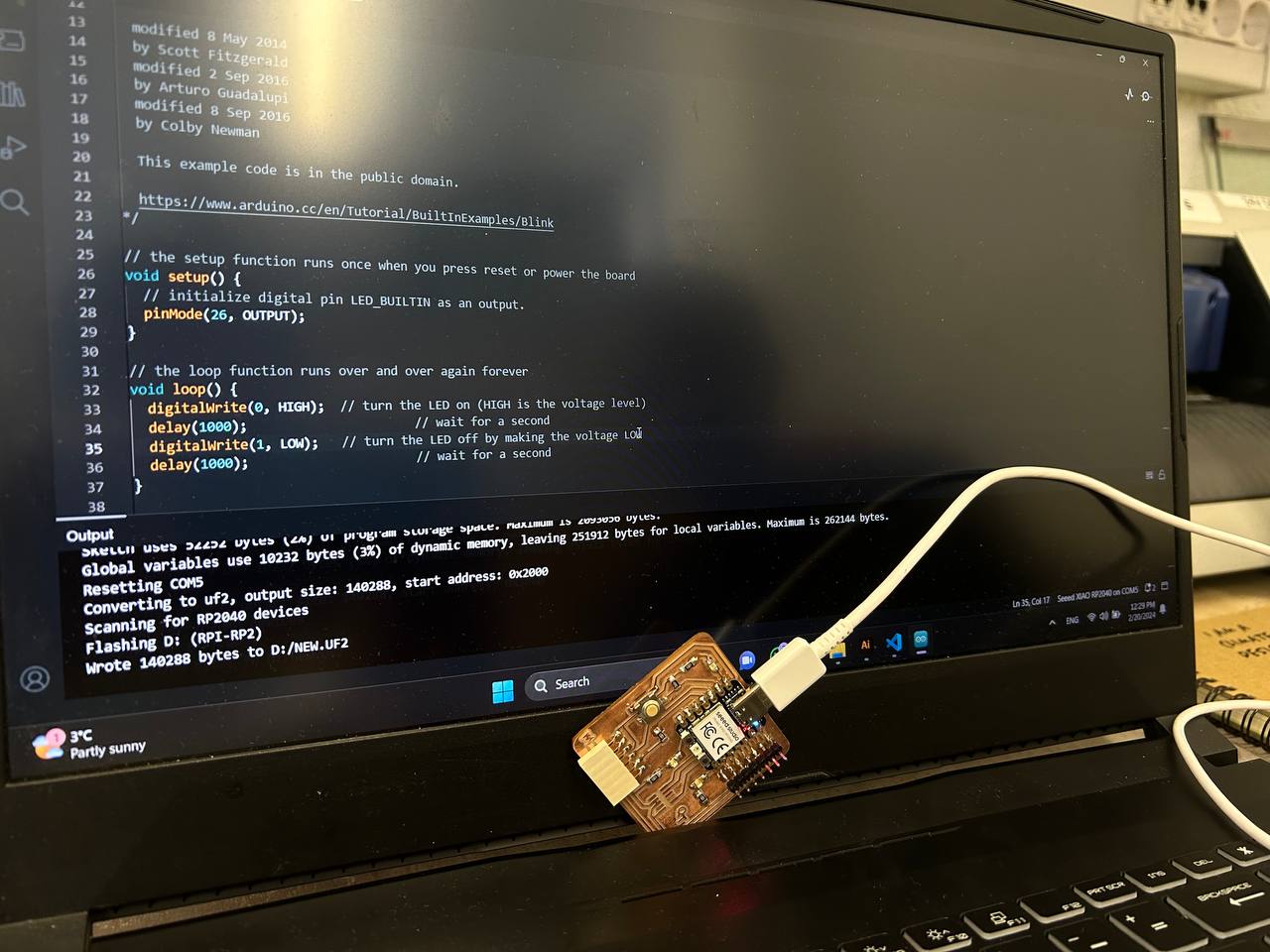 As you can notice on my notebook display there is an open software, where I have to code my microcotroller.
Arduino IDE
For coding I used Arduino IDE. Cause this software is free for downloading and also it has a very simple interface and programmed system.
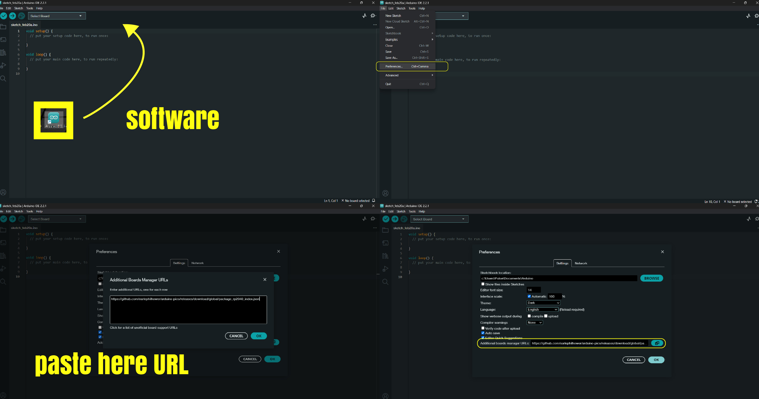
Code for pasting in URL stroke is here:
https://github.com/earlephilhower/arduino-pico/releases/download/global/package_rp2040_index.json
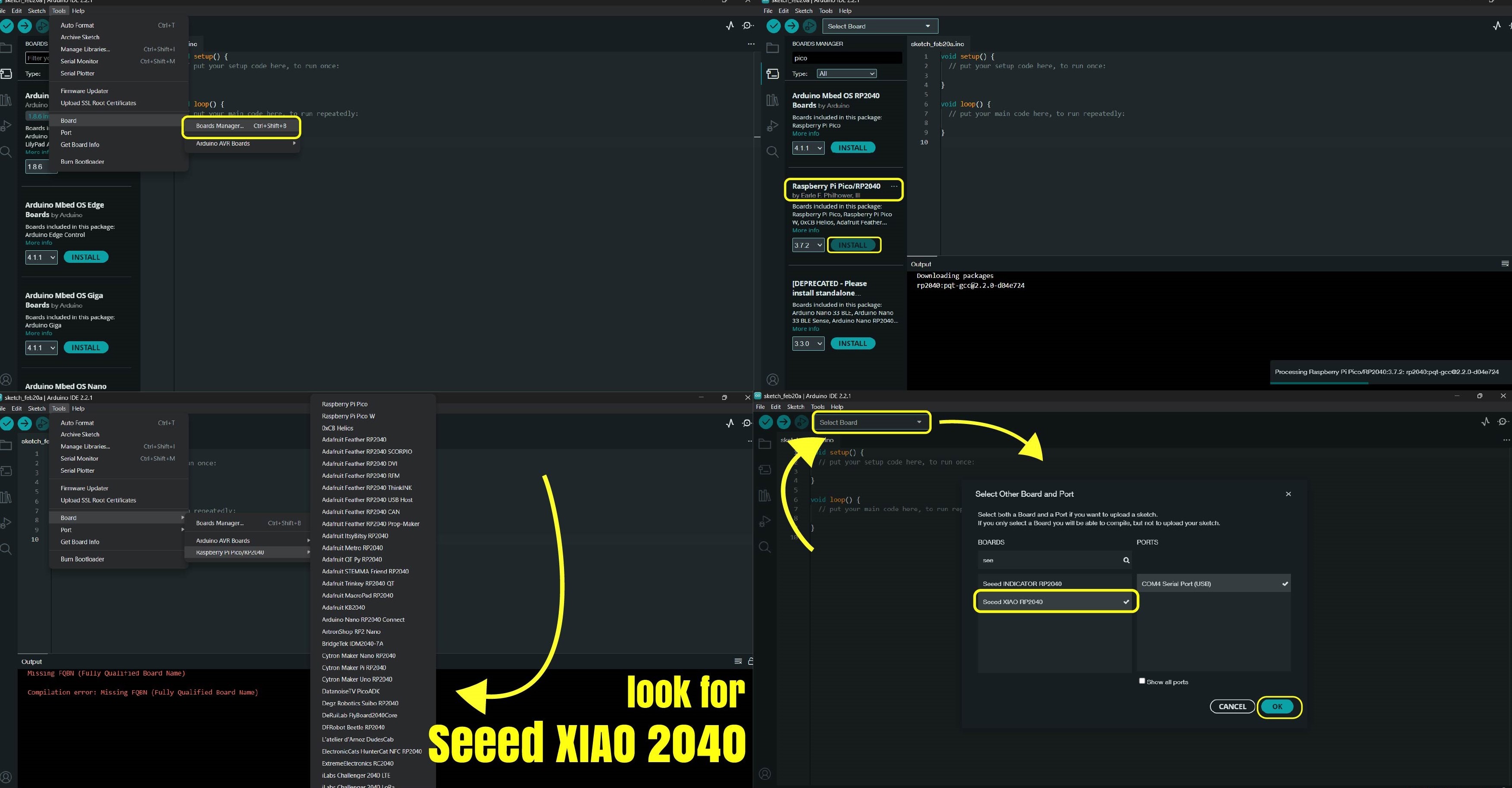
After setting URL code i downloaded Pico in the boards manager. Tools->Board->Board manager
Here in my screen you can see where my board was. I installed needed system - Xiao 2040 and setted it.
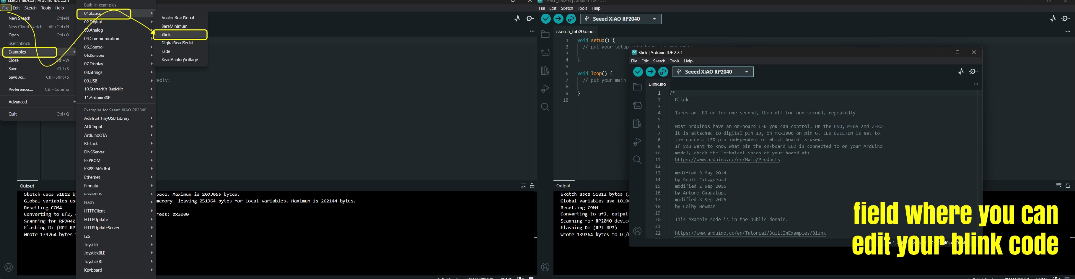
LED Blinking
After my code was ready and I uploaded it, I could see LED’s blinking on my board. First code that I write was blinking continuity. But after, I started experimenting with sequence. With that AI tools helped me a lot.
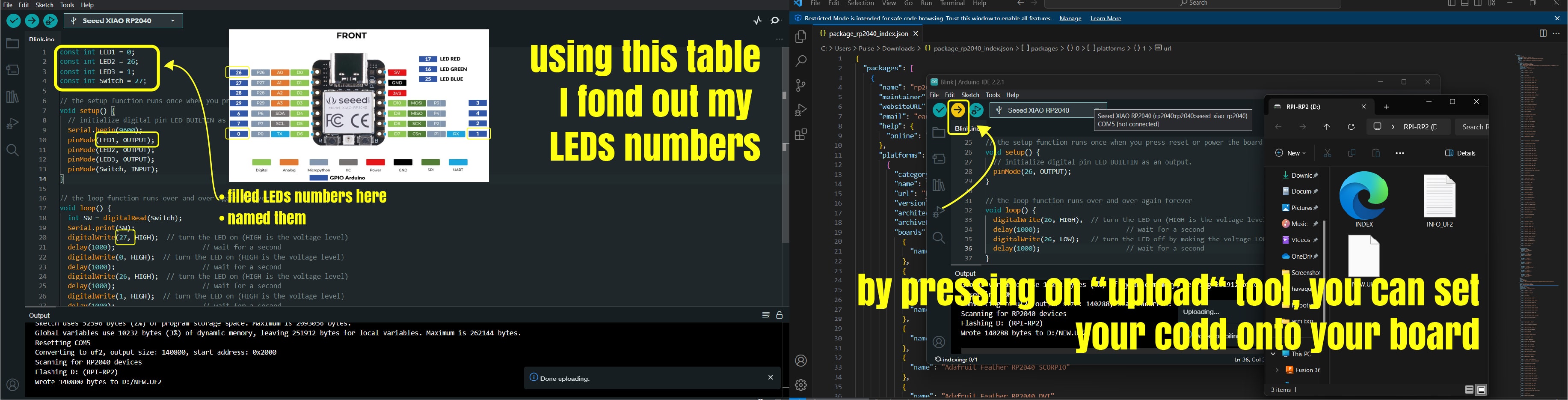
Below you can see my code in Arduino IDE.
const int LED1 = 0;
const int LED2 = 26;
const int LED3 = 1;
const int Switch = 27;

// the setup function runs once when you press reset or power the board
void setup() {
  // initialize digital pin LED_BUILTIN as an output.
  Serial.begin(9600);
  pinMode(LED1, OUTPUT);
  pinMode(LED2, OUTPUT);
  pinMode(LED3, OUTPUT);
  pinMode(Switch, INPUT);
}

// the loop function runs over and over again forever
void loop() {
  int SW = digitalRead(Switch);
  Serial.println(SW);

  if (SW == 1) {
    digitalWrite(27, HIGH);  // turn the LED on (HIGH is the voltage level)
    delay(1000);                      // wait for a second
    digitalWrite(0, HIGH);  // turn the LED on (HIGH is the voltage level)
    delay(1000);                      // wait for a second
    digitalWrite(26, HIGH);  // turn the LED on (HIGH is the voltage level)
    delay(1000);                      // wait for a second
    digitalWrite(1, HIGH);  // turn the LED on (HIGH is the voltage level)
    delay(1000);                      // wait for a second
    digitalWrite(0, LOW);   // turn the LED off by making the voltage LOW
    delay(1000);                      // wait for a second
    digitalWrite(26, LOW);   // turn the LED off by making the voltage LOW
    delay(1000);                      // wait for a second
    digitalWrite(1, LOW);   // turn the LED off by making the voltage LOW
    delay(1000);
  }
                       // wait for a second
}
Alternative way of connection
For an alternative way of connecting LED and making it blink I tried this type of connections.
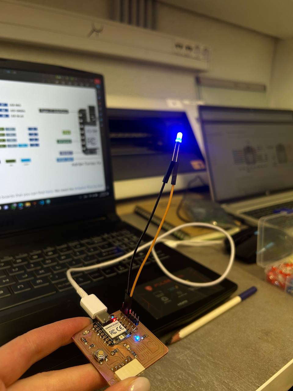
Besides that I had a problem with switching green LED cause it had 2.2V but my microcontroller had a 3.3V, so when I switched it, it just burnt. After that I used resistor for making my wanted Voltage. I counted it and switched 68 Ohm resistor but after I even tried 390 Ohm and 20 Ohm Resistors, of course they did’t work so well. There were a lower light. (In picture below it had to be written 68 Ohm)
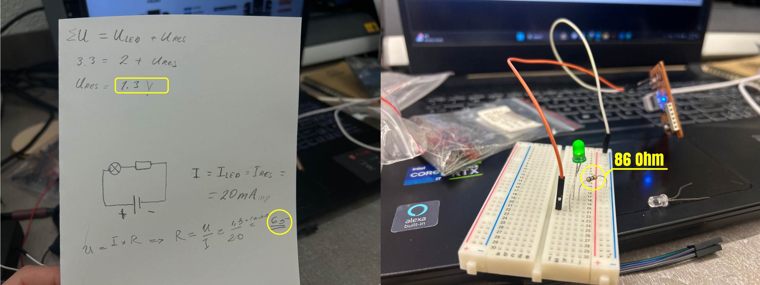
Here is the process.
Conclusion
This week was a bit harder than previous one, but I made it.
I learned a lot about components in PCB board like resistors, capacitors, microcontrollers and etc. At first it was hard for me to learn about all this components and try to use it in my assignment making. It needs some time to fill the gaps.
I’ve got acquainted with PCB board cutting-interior, exterior. At this process there were many questions, especially in making G-code by modsproject.
Also I tried soldering small components. It was very nice to solder components. I liked this process very much. It requires patience a lot.
I learned Arduino IDE template with blinking and changed blinking sequence of my LEDs in my PCB board.