4.Electronics Production
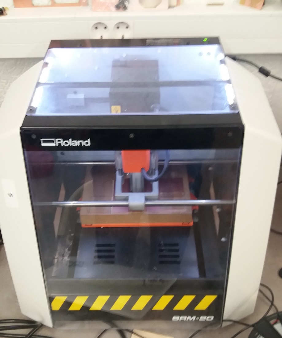
In our laboratory, we use a Roland SRM-20 CNC machine to cut out the board.
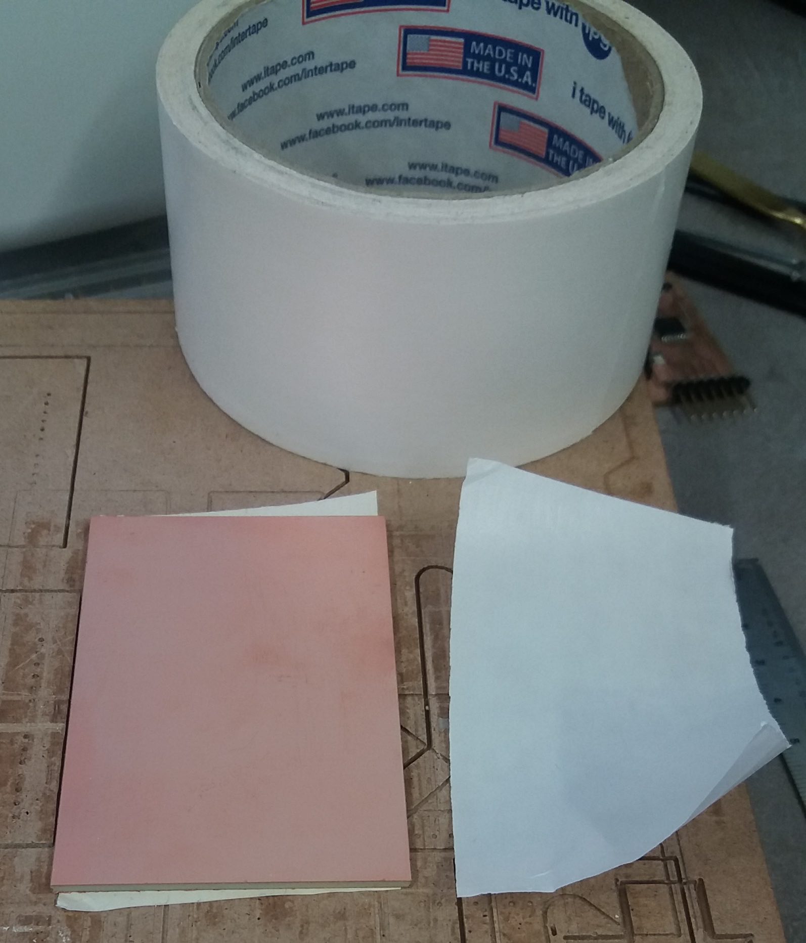
Attaching the board to the table
We attached the new board to the MDF table using double-sided tape. To improve fastening, clamps and pieces of wood are sometimes used to hold the board to the table. However, we can also do this by hand, depending on the size of the board.
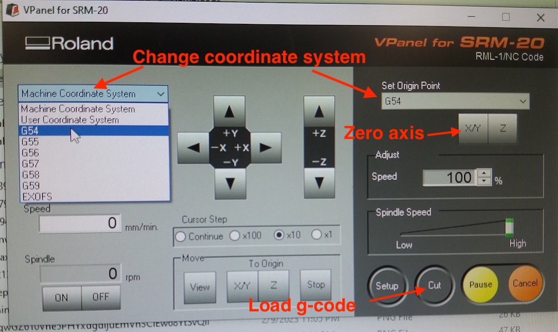
Software control
The software we use to control the CNC “VPanel for SRM-20”:
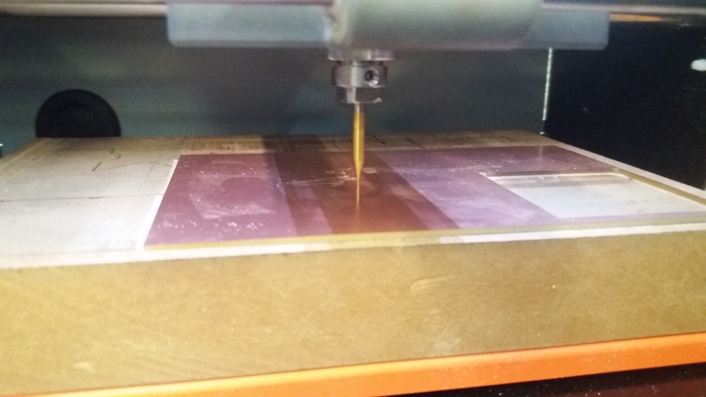
Reset the Z axis
To zero the Z axis, we manually lower the cutter closer to the board. Once it is close enough, we use the appropriate hex key to release the cutter and carefully lower it until it makes contact with the board. After contact we tighten the screw and zero the Z axis.
V-cutter testing
For a group assignment, we tested a V-cutter. Know what its diameters are at each depth and know how to adjust the settings for different thicknesses. o We started with a simple test drawn in Inkscape.
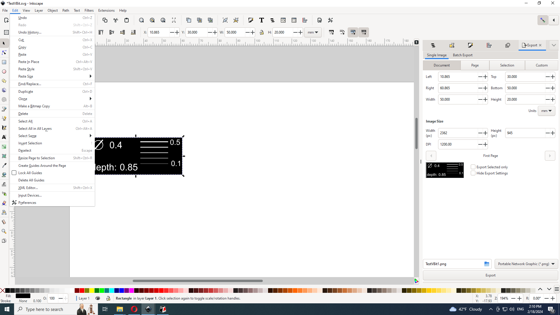
To generate G-code, we decided to use Fab Mods. Here it is possible to generate G-code using files of different formats. We use the SVG format as a drawing.
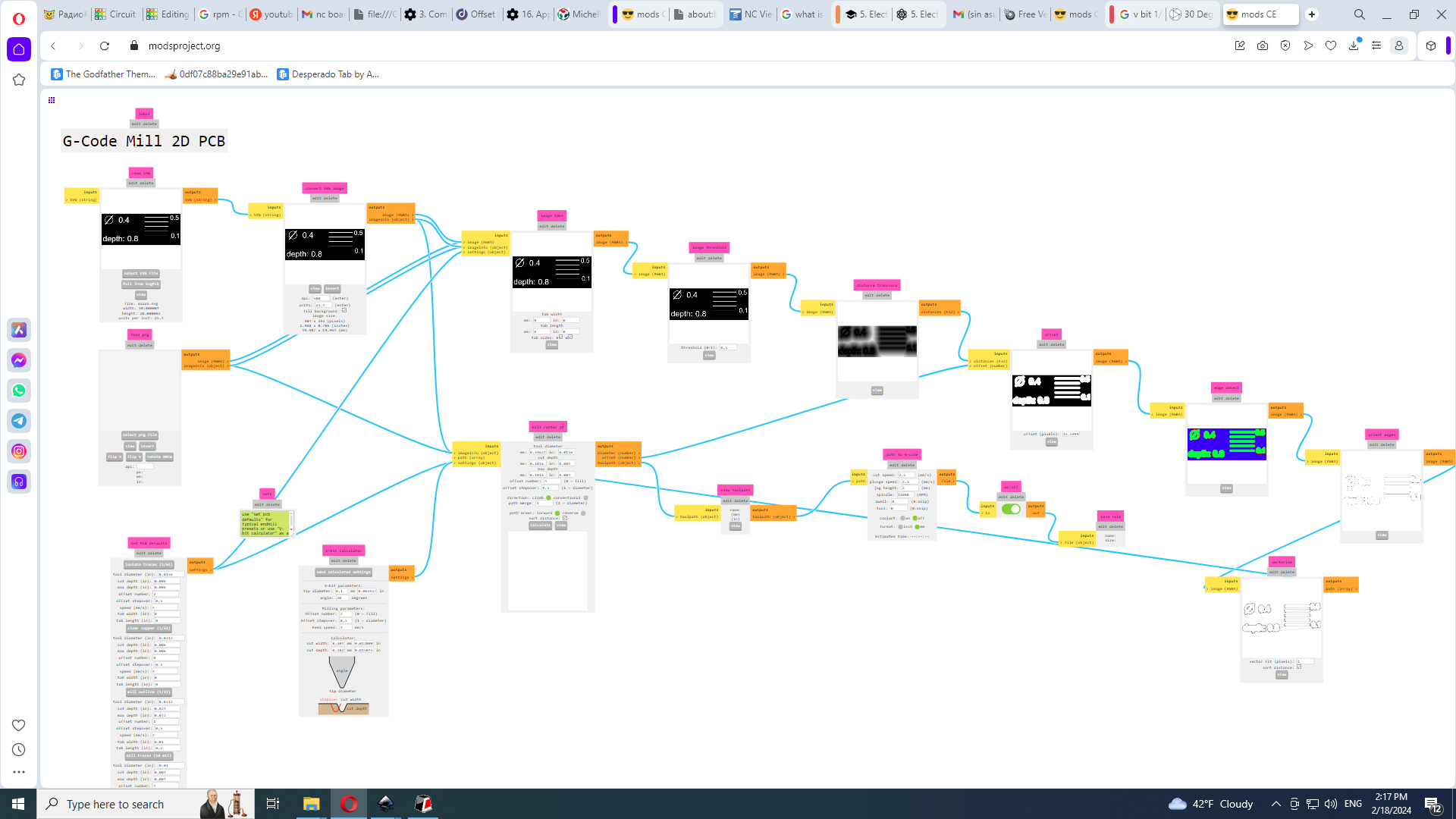
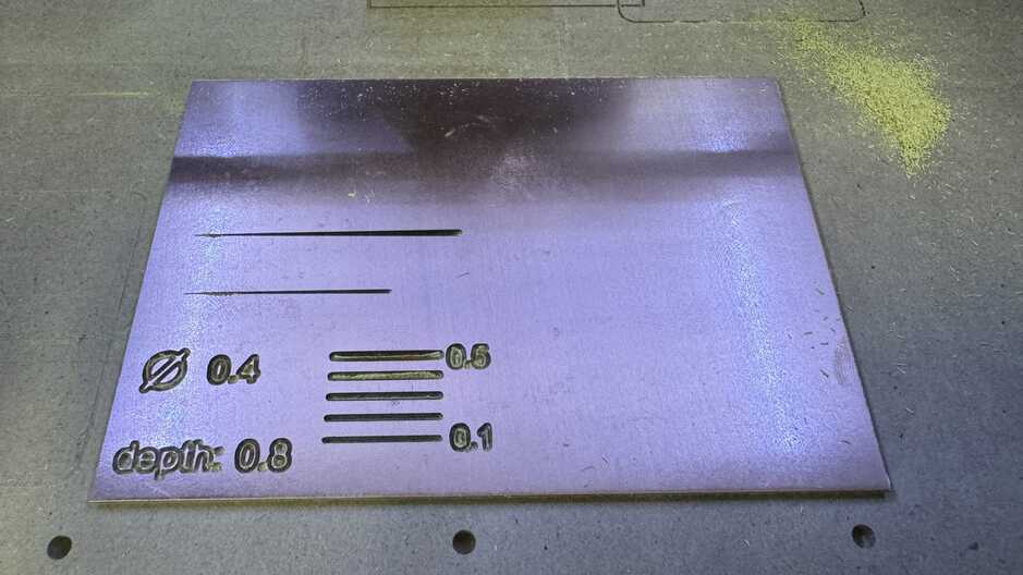
We set the fictitious tool diameter to 0.4 here because we didn’t know what it would be at each depth. and started with a depth of 0.8 to engrave several lines ranging from 0.1 to 0.5 mm thick.
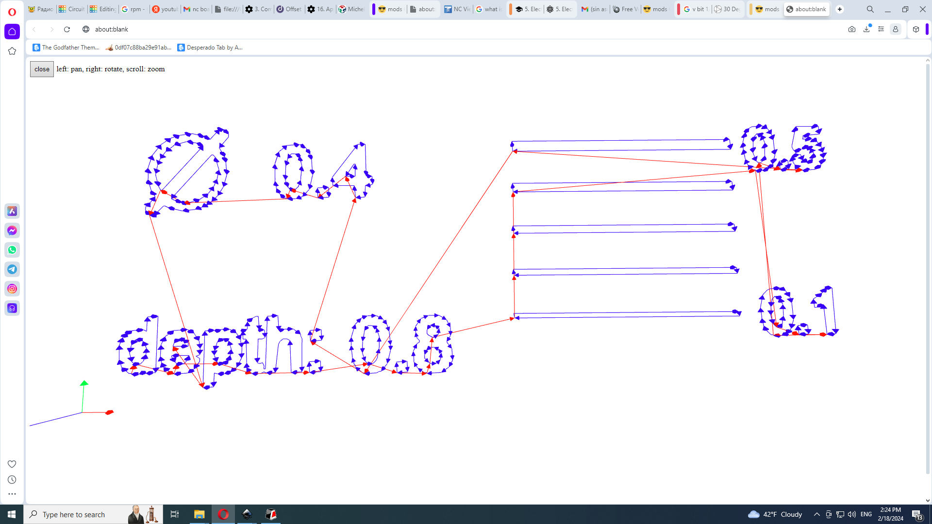
Then we generated a G-code and previewed the cutting path:
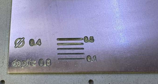
We installed the cutter, loaded the G-code and started engraving these lines and got the following result:
Manually writing g-code
Due to the long time it takes to test when engraving, we decided to create one line going down a certain distance and then measure it. To do this, we forced the cutter to rotate and move only along one axis, increasing the depth.
It was a fascinating experience that we gained thanks to Ashot manually generating g-code.
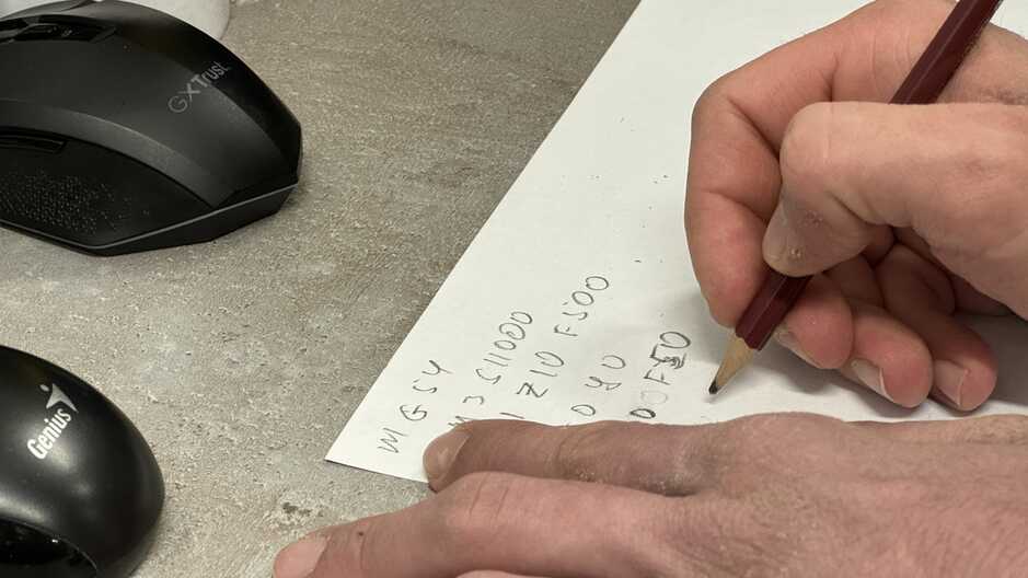
Ashot wrote the following code:
%
G17
G21
G40
G49
G54
G80
G90
G94
S11000
G00Z2.0000
M03
G00Z2.0000
G00X0.0000Y0.0000Z2.0000
G01 Z0 F100
G01 X40 Z-1.6
Z50
M05
M30
%
Having given this code to the program, we got the following result:
Calculation of the recess of a V-shaped cutter
We also drew a V-cutter shape with actual dimensions and tried to solve it mathematically:
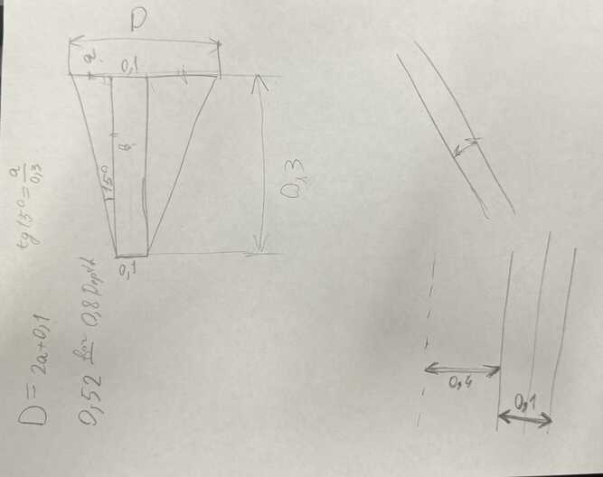
Also, since we did not know the tip diameter of the V-cut, we assumed a value of 0.2 mm. Areg developed a formula for calculating the necessary parameters.
During the testing and measuring process, Areg and I created a drawing in Solidworks that automatically measures each depth. In case the cutter tip diameter is indeed 0.1 mm, we used this value in the calculations. However, we also had the option to change this setting to 0.2mm.
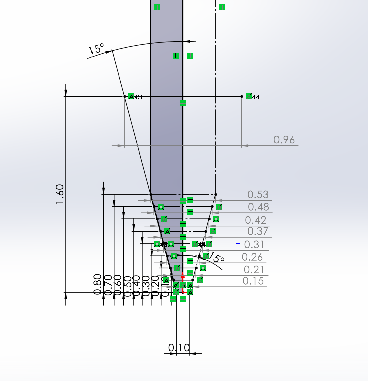
Since we did not know the tip diameter, we assumed it to be 0.1 mm. However, we could also change this parameter to 0.2 mm or another value if necessary. These uncertainties can lead to some inaccuracies in the measurements, but we used theoretical approaches to calculate the depth and thickness at a 30 degree angle using the parameters of the model created in Solidworks.