11. Input devices
Group assignment:
- Probe an input device(s)’s analog levels and digital signals
This week’s group assignment was led by support instructor Maxim Richard.
This week our group has been exploring analog levels and digital input device signals. We tested the HC-SR04 digital ultrasonic rangefinder sensor and the Sharp GP2Y0A21YK0F analog sensor.
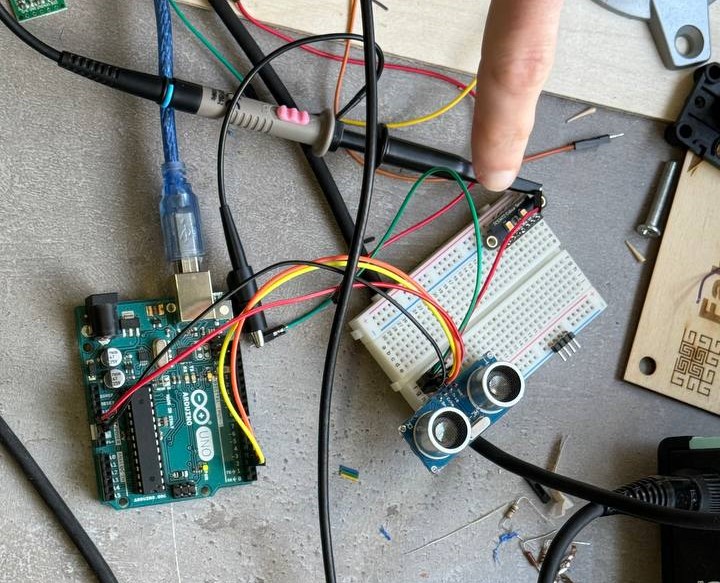
HC-SR04 digital sensor
First of all, we decided to explore the HC-SR04 digital ultrasonic rangefinder sensor. In order to see the sensor in action, you need to connect it to a microcontroller and write code. We connected the sensor to the Arduino UNO board. To provide power to the sensor, we connected the Vcc and GND pins to the corresponding Arduino UNO pins. The Trig pin of the sensor was connected to the 9th pin of the board, and the Echo pin to the 10th pin.
Code Without library
From the beginning we wrote the code without using libraries
const int trigPin = 9;
const int echoPin = 10;

float duration, distance;

void setup() {
  pinMode(trigPin, OUTPUT);
  pinMode(echoPin, INPUT);
  Serial.begin(9600);
}

void loop() {
  digitalWrite(trigPin, LOW);
  delayMicroseconds(2);
  digitalWrite(trigPin, HIGH);
  delayMicroseconds(10);
  digitalWrite(trigPin, LOW);

  duration = pulseIn(echoPin, HIGH);
  distance = (duration*.0343)/2;
  Serial.print("Distance: ");
  Serial.println(distance);
  delay(100);
}
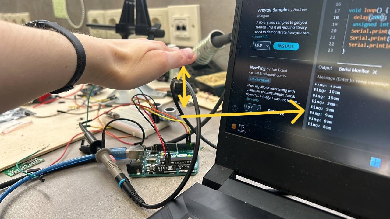
NewPing.h library code
Then we wrote the code using the NewPing.h library:
#include <NewPing.h>
#define TRIGGER_PIN 12 // Arduino pin connected to the sensor's trigger pin
#define ECHO_PIN 11    // Arduino pin connected to the sensor's echo pin
#define MAX_DISTANCE 200 // Maximum distance to measure (in centimeters)

NewPing sonar(TRIGGER_PIN, ECHO_PIN, MAX_DISTANCE);

void setup() {
    Serial.begin(9600);
}

void loop() {
    delay(50); // Wait for sensor stability
    unsigned int distance = sonar.ping_cm();
    Serial.print("Distance: ");
    Serial.print(distance);
    Serial.println(" cm");
}
Output of distance values
Then we looked at the values received from the sensor via Serial Monitor:
Pulses through an Oscilloscope
We also tested the sensor using an oscilloscope:
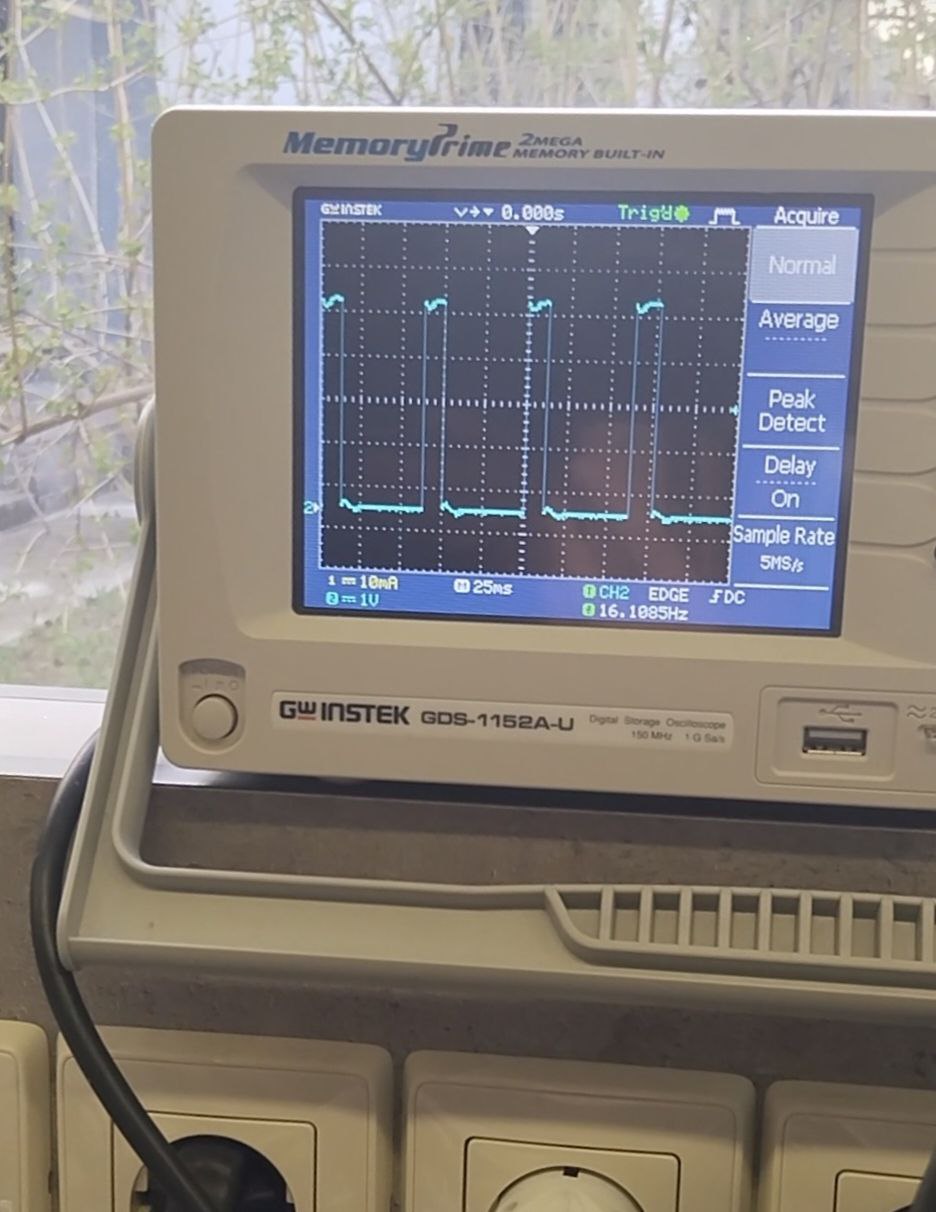
When the object is closer to the sensor, the amplitude of the wave on the oscilloscope decreases.
Sharp GP2Y0A21YK0F analog sensor
After that, we began using the Sharp GP2Y0A21YK0F sensor. This distance sensor operates on infrared (IR) light and utilizes it for distance measurement. Its principle of operation is as follows: the sensor emits an infrared beam towards an object. When the beam reflects off the object, it reaches a light detector (position sensing device or PSD). The position of the reflected beam on the PSD changes depending on the object’s position. The sensor’s built-in signal processing circuit calculates the distance based on the position of the optical spot on the PSD and outputs an analog signal corresponding to the distance to the object in front of the sensor.
Dependency search
First we decided to simply write the following code:
#define IR_SENSOR_PIN A0

void setup() {
    Serial.begin(9600);
}

void loop() {
    int sensorValue = analogRead(IR_SENSOR_PIN);
    Serial.println(sensorValue);
}
and see what values the sensor produces
We decided to conduct research and find the relationship between the value obtained from the analog pin and the distance. A good platform for this work is Excel.
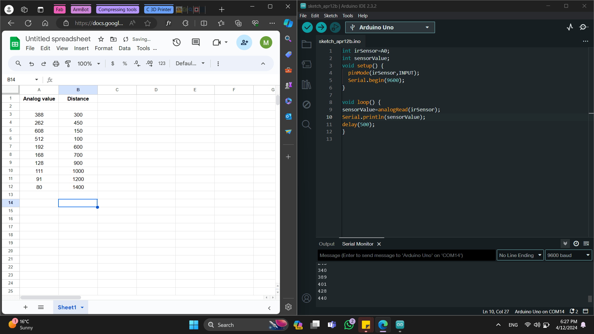
In the SERIAL MONITOR we received values from an analog sensor:
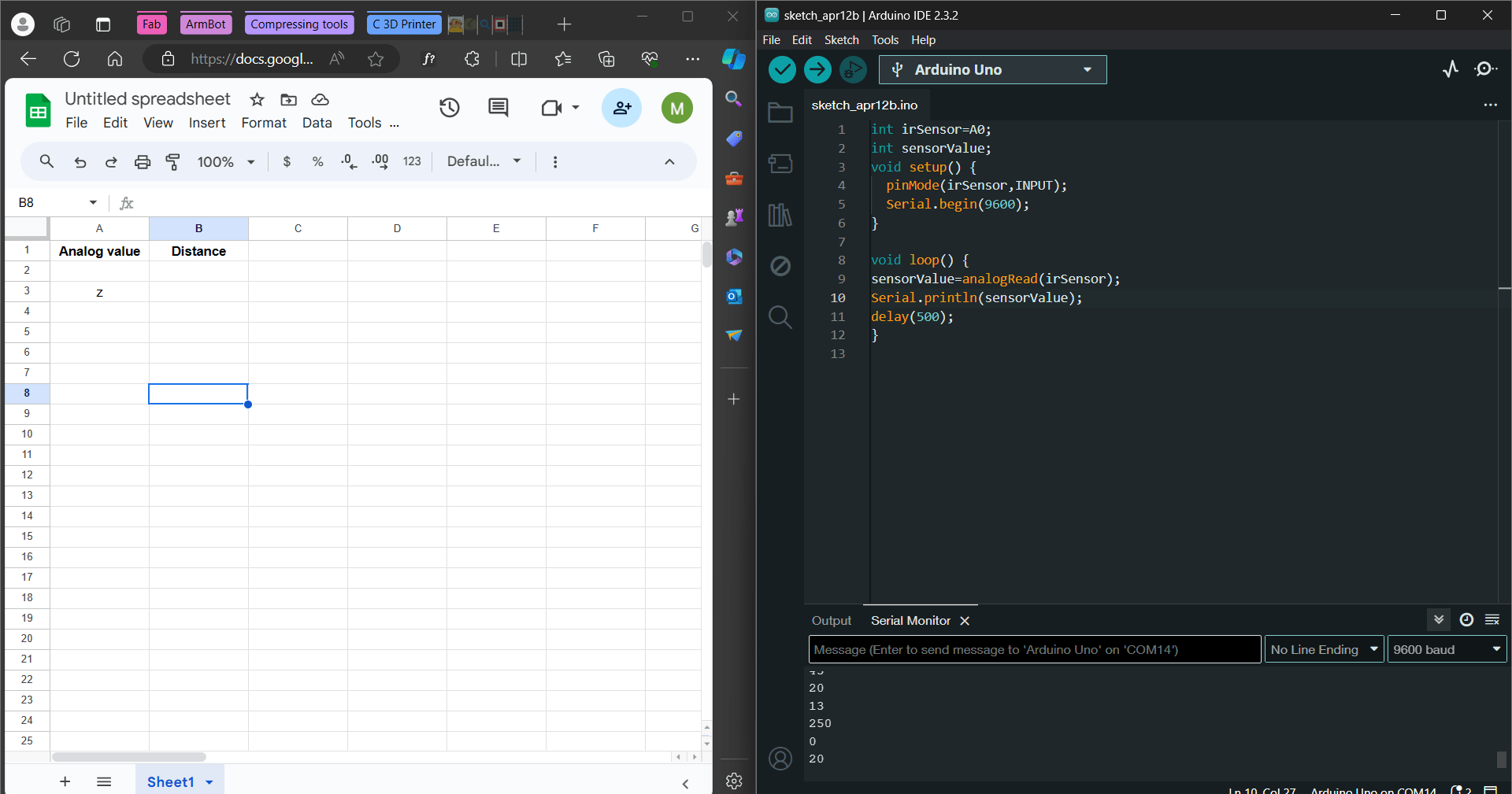
and at the same time the distance to the object was measured:
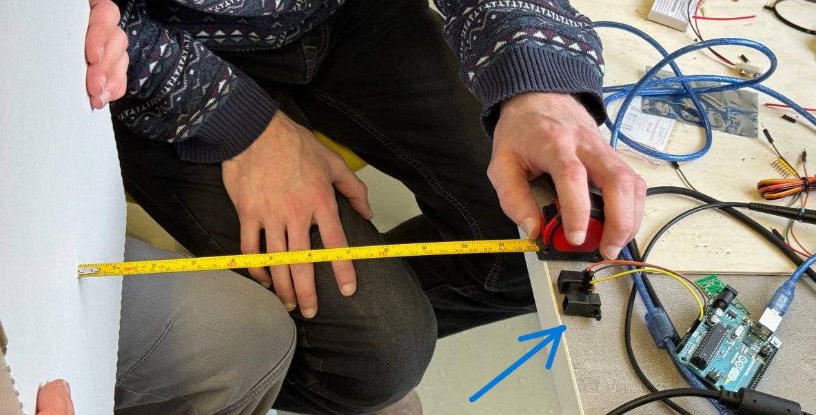
We entered our data into an Excel spreadsheet, dividing it into two columns: one for the analog values and the other for the distances we measured accordingly.
Then we changed the location of the values and got the following graph and function:
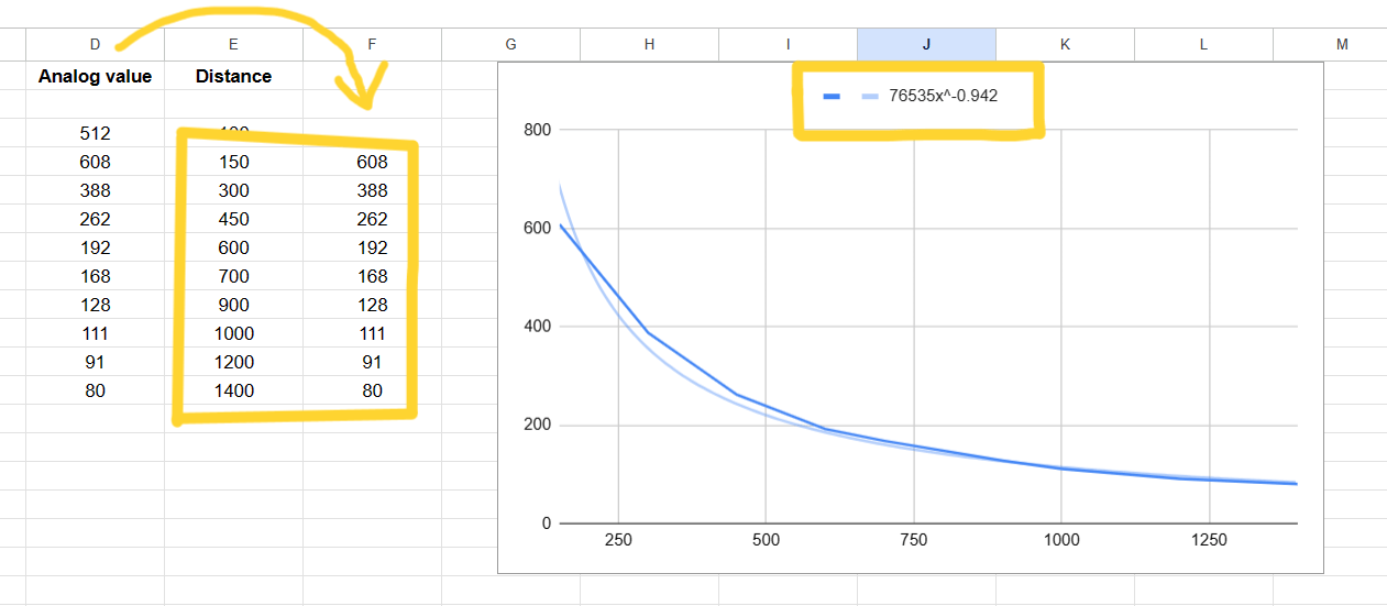
We received the following dependence of distance on analog values:
f(x) = 76535x^(-0.942)
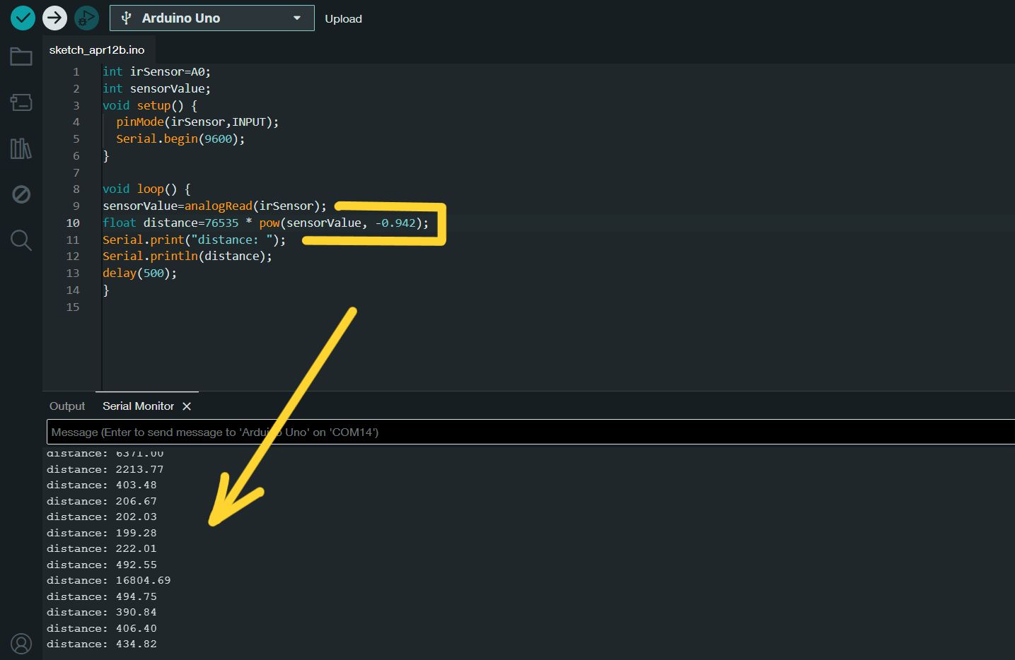
We then modified the code to the following:
int irSensor=A0;
int sensorValue;
void setup() {
  pinMode(irSensor,INPUT);
  Serial.begin(9600);
}

void loop() {
sensorValue=analogRead(irSensor);
float distance=76535x * pow(sensorValue, -0.942);
Serial.print("distance: ");
Serial.println(distance);
delay(500);
}
Even though the modified code worked, it was still lacking in accuracy. Potential factors that could contribute to this deficiency include ambient lighting, noise interference, or the need for additional measurements.
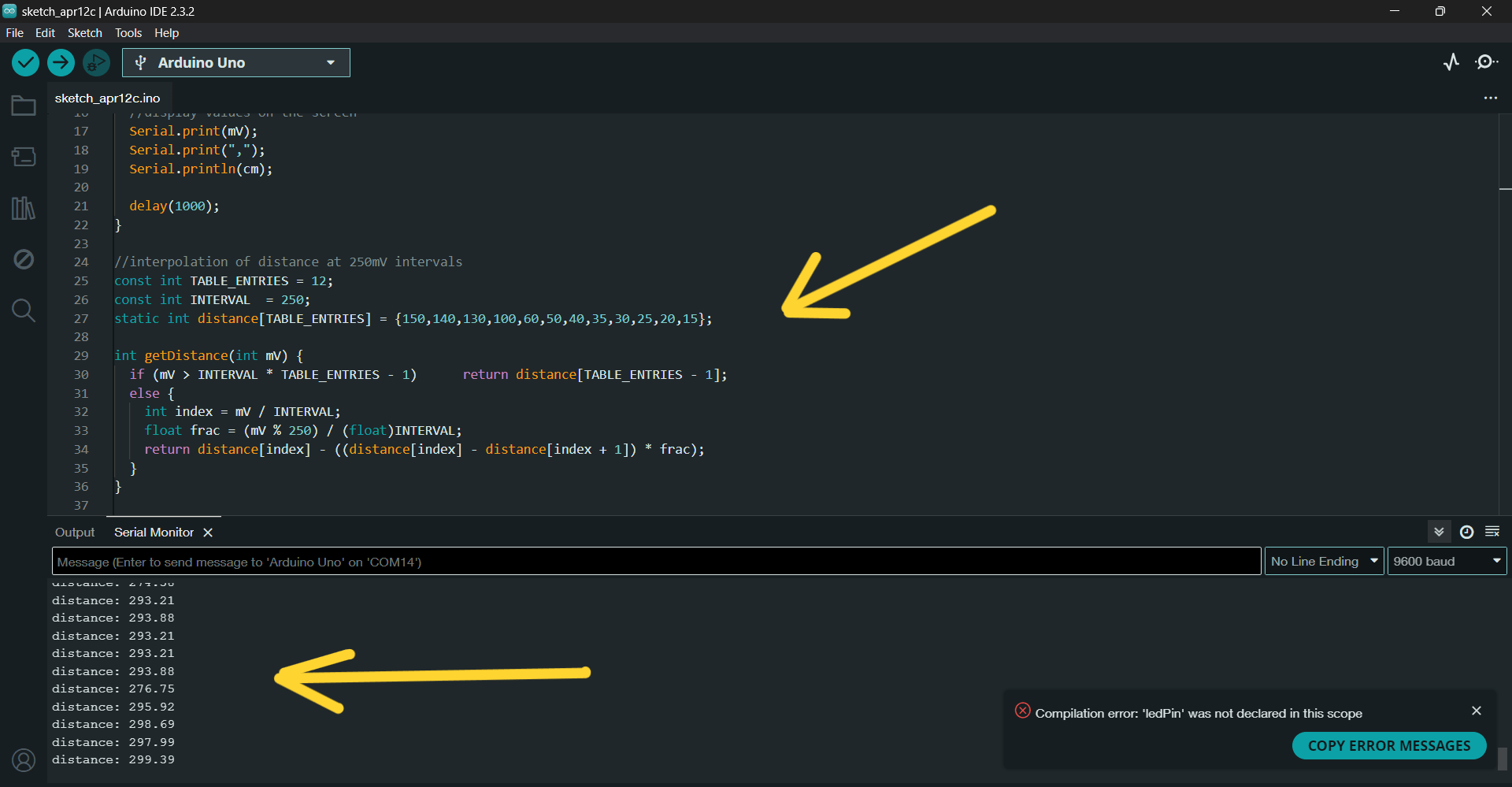
Code using the NewPing library
We then found the code using the NewPing library and loaded it onto the board:
const int sensorPin = A0;
const long referenceMv = 5000;

void setup() {
  Serial.begin(9600);
  pinMode(ledPin, OUTPUT);
}

void loop() {
  //reading the voltage
  int val = analogRead(sensorPin);
  int mV = (val * referenceMv) / 1023;
  int cm = getDistance(mV);


  //display values on the screen
  Serial.print(mV);
  Serial.print(",");
  Serial.println(cm);

  delay(1000);
}

//interpolation of distance at 250mV intervals
const int TABLE_ENTRIES = 12;
const int INTERVAL  = 250;
static int distance[TABLE_ENTRIES] = {150,140,130,100,60,50,40,35,30,25,20,15};

int getDistance(int mV) {
  if (mV > INTERVAL * TABLE_ENTRIES - 1)      return distance[TABLE_ENTRIES - 1];
  else {
    int index = mV / INTERVAL;
    float frac = (mV % 250) / (float)INTERVAL;
    return distance[index] - ((distance[index] - distance[index + 1]) * frac);
  }
}
This code was already working correctly and produced the correct distance values: