8. Electronic design
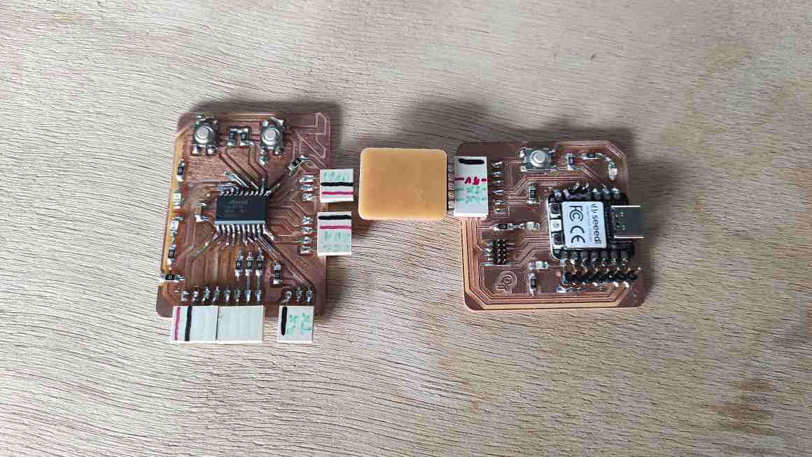
Hero Shot
Assignment :
Group assignment:
- use the test equipment in your lab to observe the operation of a microcontroller circuit board
- send a PCB out to a board house
Individual assignment:
- use an EDA tool to design a development board to interact and communicate with an embedded microcontroller, produce it, and test it
- extra credit: try another design workflow
- extra credit: design a case for it
- extra credit: simulate its operation
Group Assignment
You can find our group page here and this week group assignement here
Individual Assignment
Kicad Basics
To start our week, we participate to a workshop to learn Kicad basics. We learned to add libraries for symbols and footprints, then we used the SAMdino documentation and try to recreate it in the Schematic Editor then export it in the PCB editor.
In the absence of our instructor we struggled a lot to understand how every components works together and we couldn’t succeed at replicating it but we learned to use a bit of the Software.
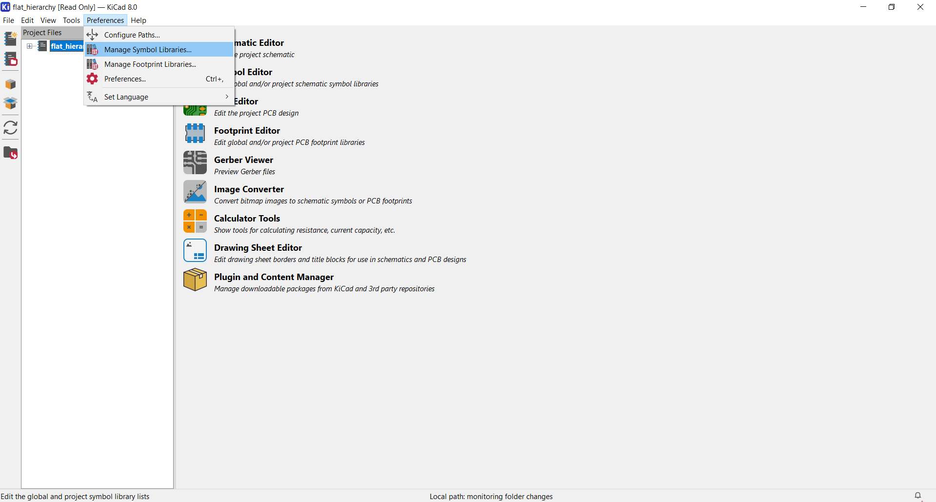
Adding Libraries
Before anything, we dowloaded the Fab Electronics Library for Kicad and followed the Readme.md to install it and import Symbol and Footprint Libraries.
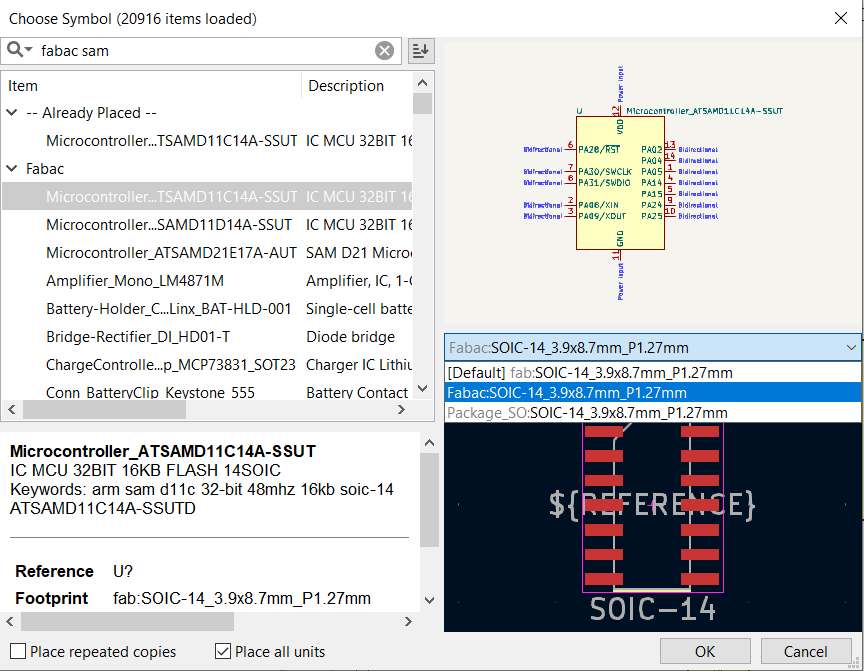
We found out later there’s some default link errors between symbols and footprints (fab or fabac library) and we need to select the right footprint when choosing a component.
Schematic Editor
After creating a new project, we need to open the schematic editor.

Here’s the principal functions we used for the schematics.
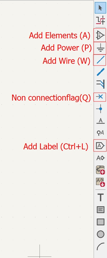
When adding a symbol, we searched for components in the Fabac Library and added it to our schematics. NB : We found out later there’s some default link errors between symbols and footprints (fab instead of fabac library) and we need to select the right footprint when choosing a component.
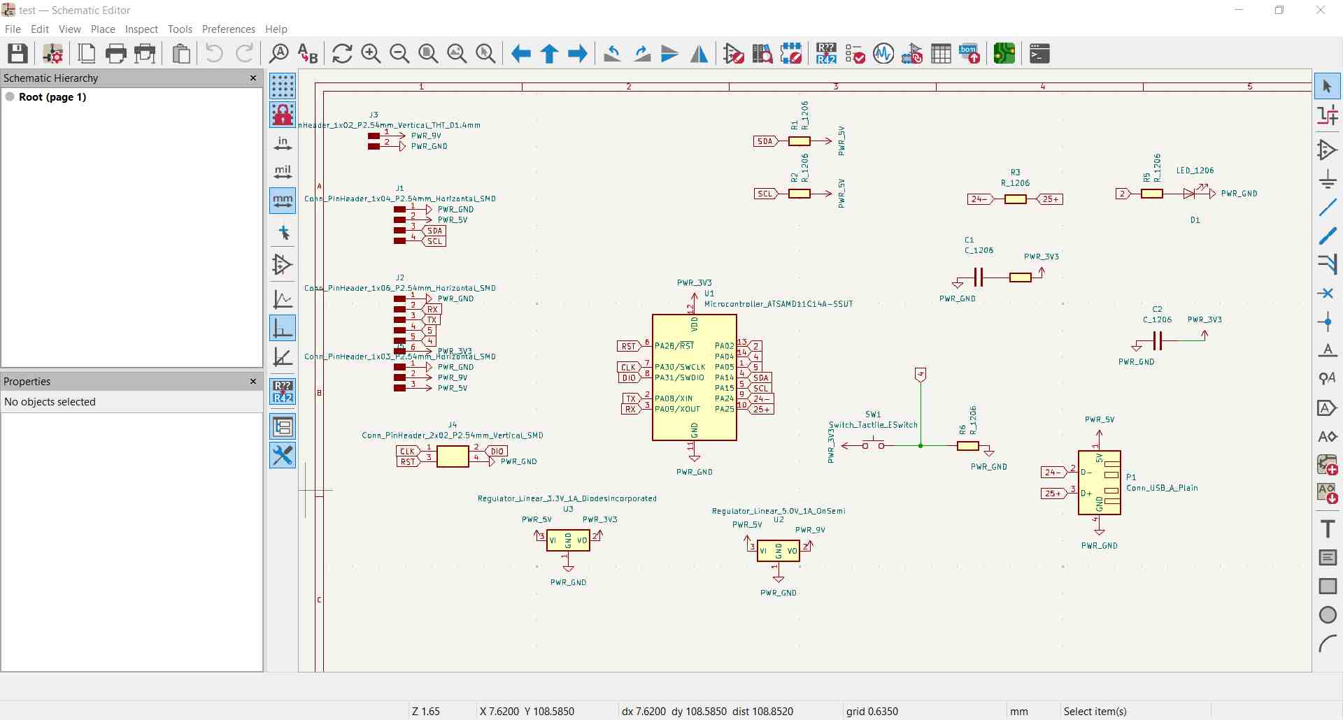
We manage to add all components and link them with wire and labels. We can turn all elements using “R” shortcut.
PCB Editor
Then we click “open PCB Editor” then import footprints and place them a bit like the Samdino.
Blue lines correspond the schematic link between components and we had to trace paths between them.

At this moment, this design was quite overwhelming and we don’t mange to finish it.
Personal Design
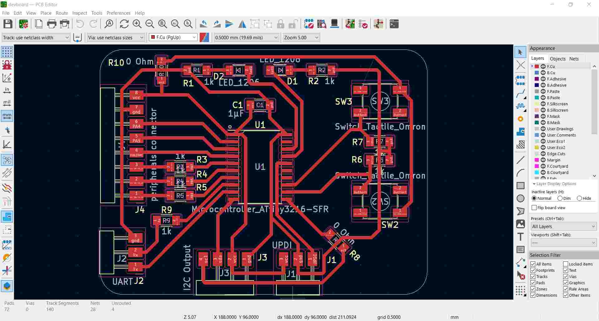
After this failure, I started again with a more simple board, trying to fulfill the requirement for my final project. I chose an ATtiny3216-sfr micro-controller, because it has lot of pins for my numerous inputs. But I’m not sure it can communicate with an e-paper screen.
I decided to create different type of connexion UART, UDPI and allowed to use numerous peripherals including I2C.
I first make search about connexions using different websites and threads :
I also checked ATtiny 3216 datasheet.
I didn’t undertsand every thing but I wanted to give a try to a first design. I couldn’t particpate to the Global OpenTime but I watched the replay and it helped me a lot
I decided to make a board with UART connector, UDPI for programming, I2C to test displays, and multiple I/O with or without resistor. I also add buttons and LEDs to make tests on boards. At first, I designed a Reset Button but as it share pin with the UDPI, that wasn’t very relevant.

I imported the foot prints in the PCB editor and manage to create the paths using some 0 Ohm Resistors.


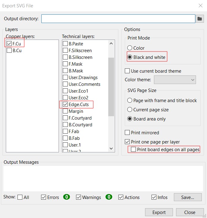
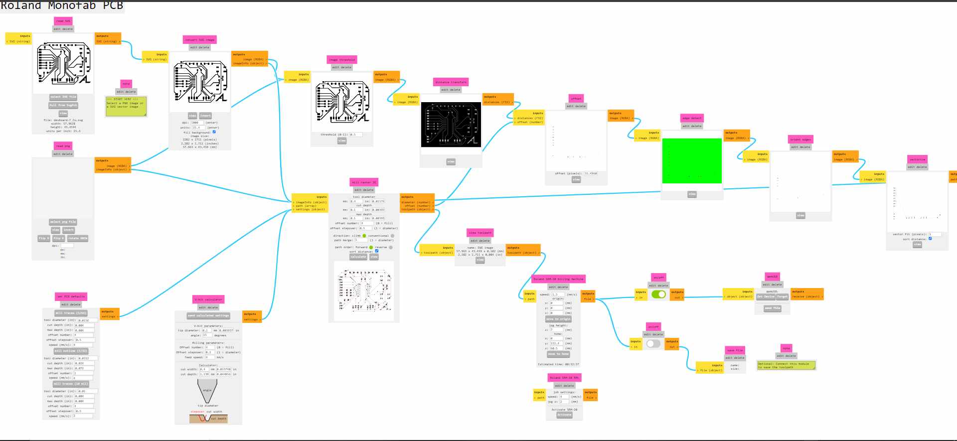
I could export my design in SVG selecting the right layers, checking black and white and unchecking “Print board edges on all pages” to create an RML with modsproject.

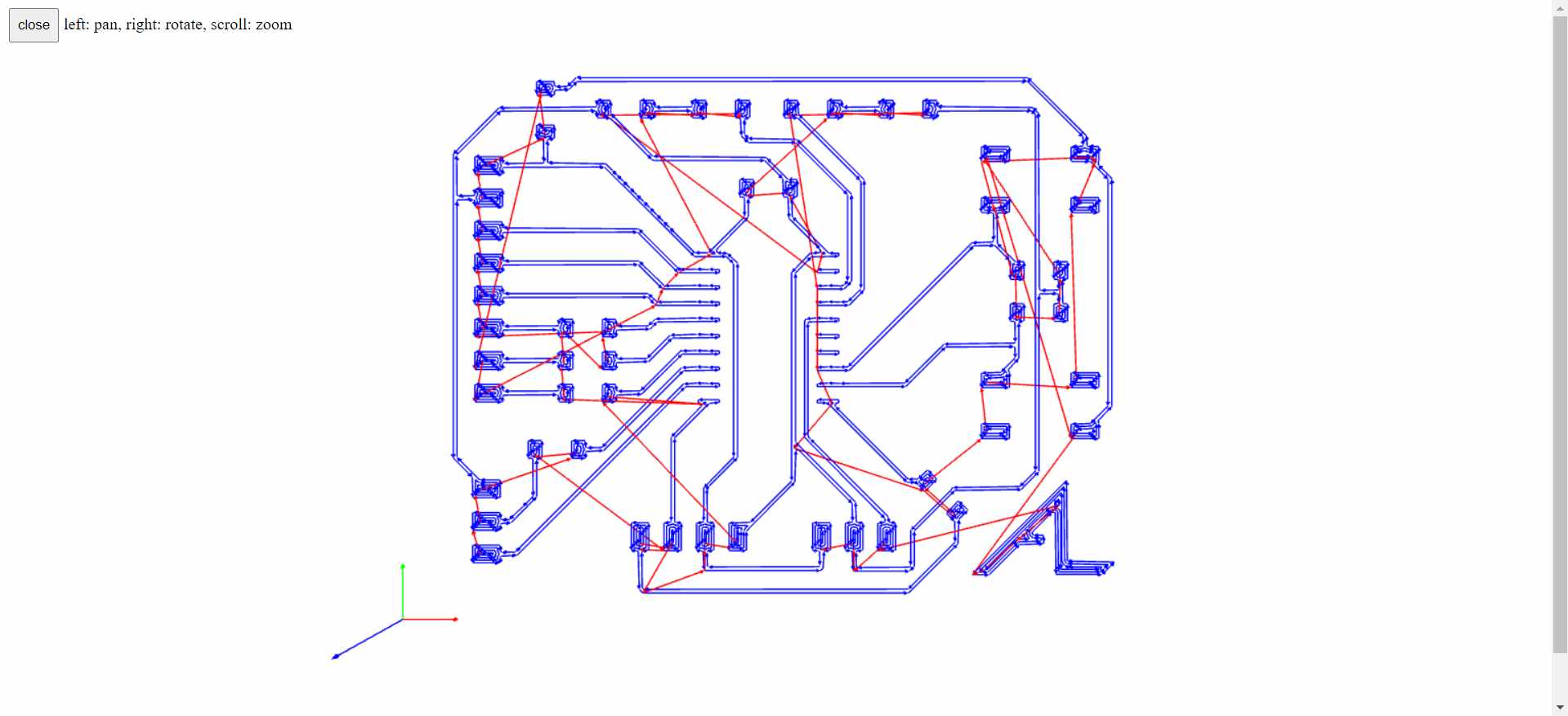
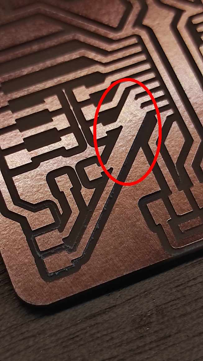
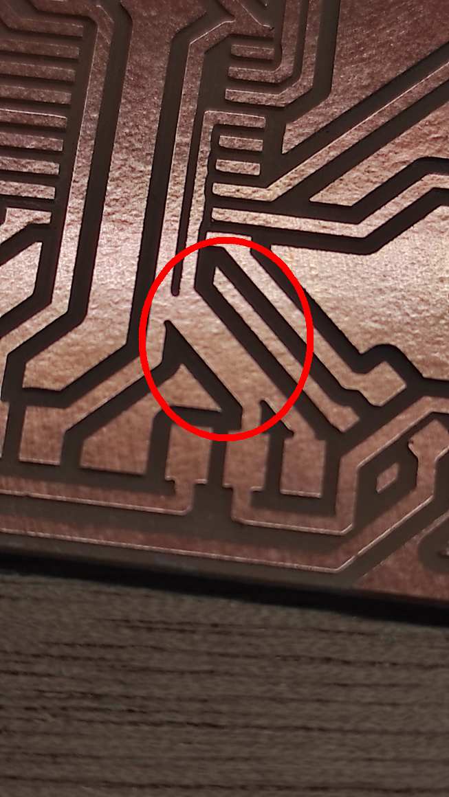
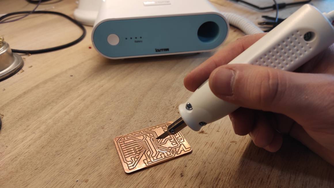
I could milled the PCB but some paths were too close so i used an ultrasonic cutter too separate them.

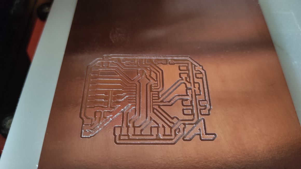
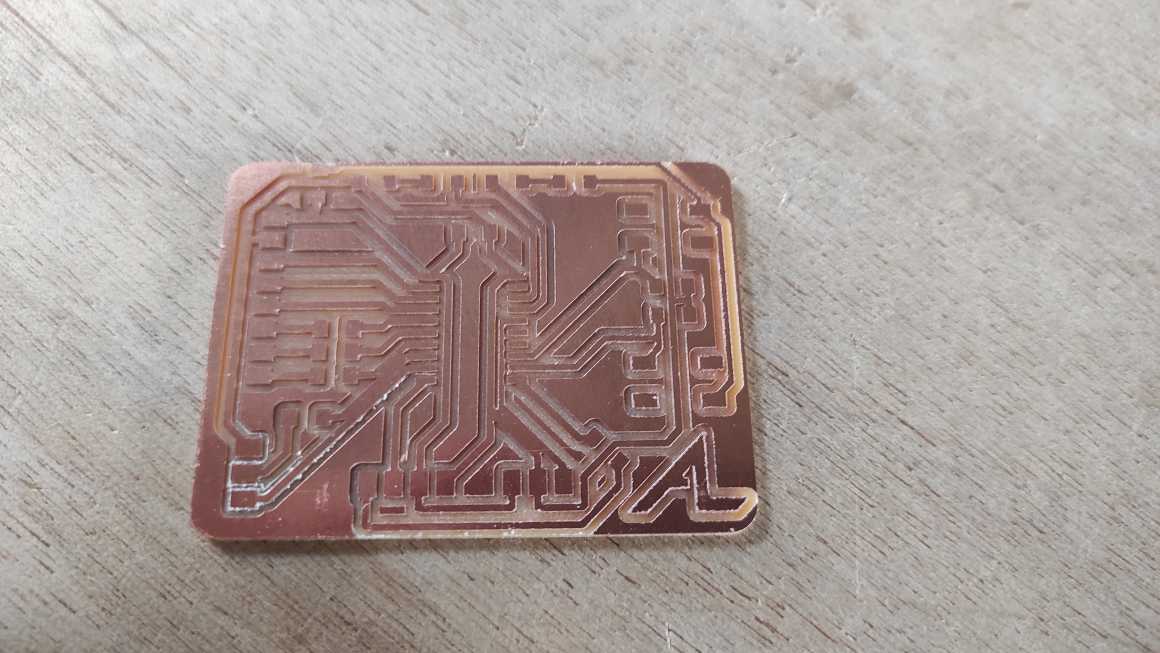
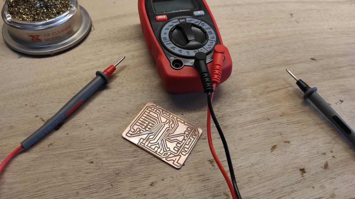
I tested all the paths with a multimeter to check unattended connexion and prepared all the components.
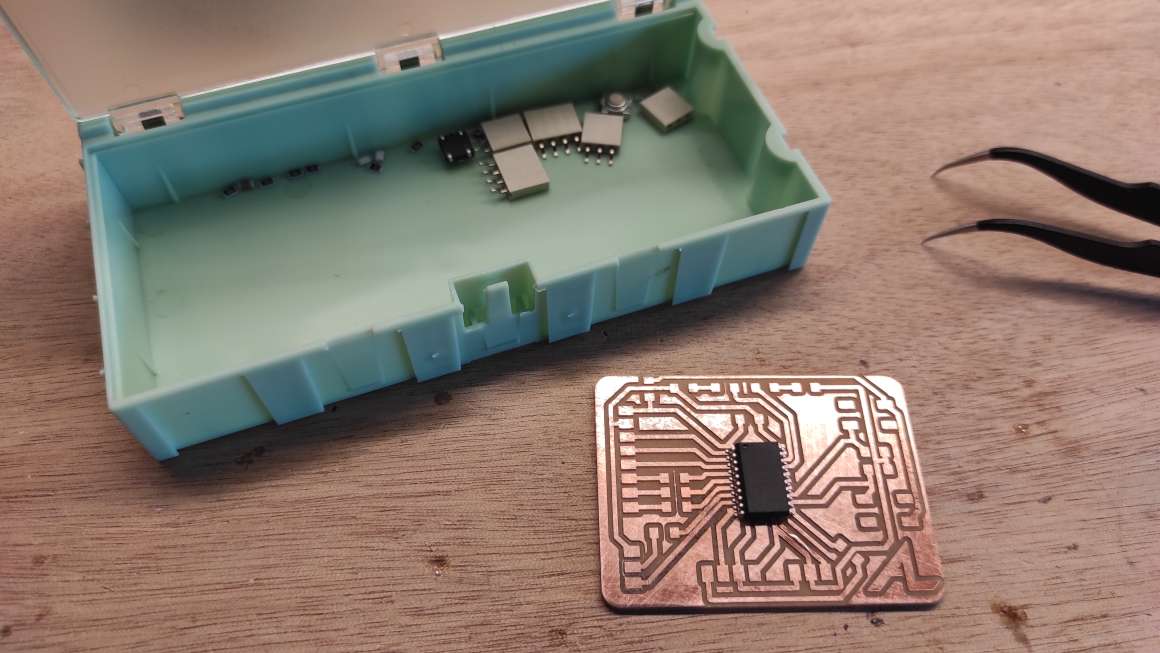
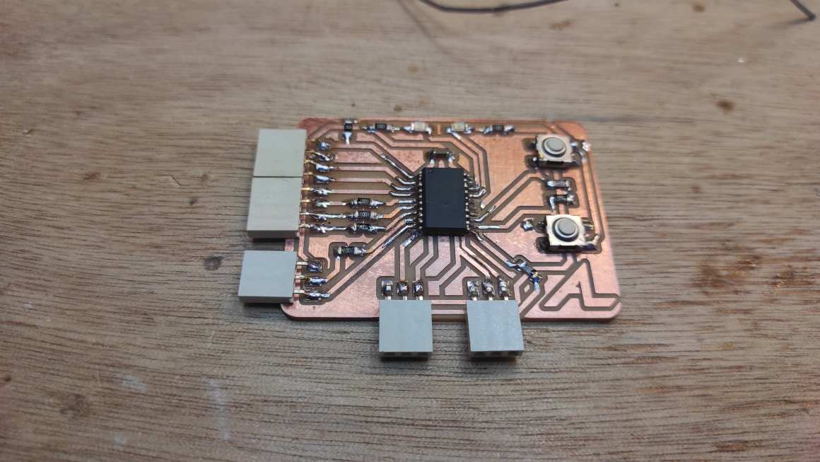
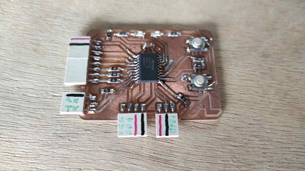
I soldered all the components without too much difficulties.

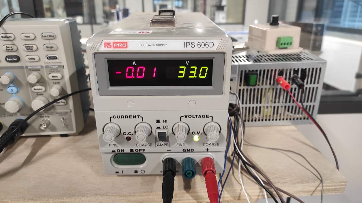
And then, I made an enormous and dangerous mistake due to fatigue, haste, and lack of attention.
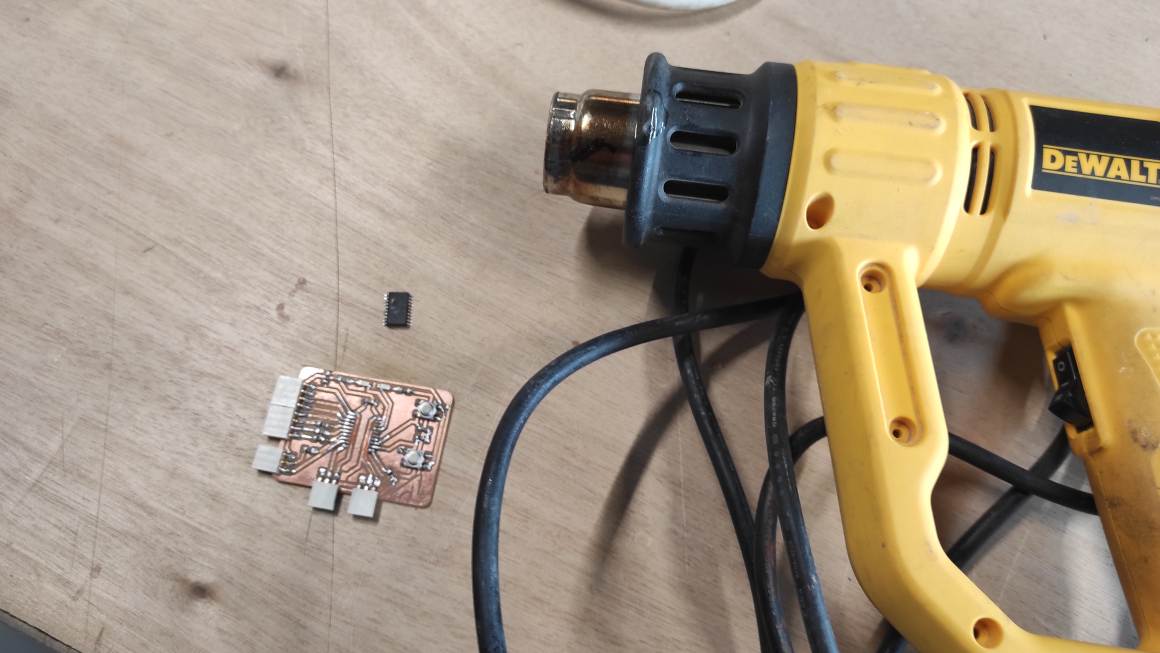
I tested my board at 33V instead of 3.3V and the chip immediatly burned.
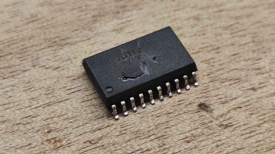
I desoldered it with a heat gun and replace the chip. I also replaced a wrong connector 1x03 for a 1x04 for the I2C.
Programming
I found the megaTiny repository for the AtTiny Library for Arduino IDE and the URL to add in the IDE preferences to install it. I wanted a simple blink program to test the board. I followed the Quentorres Git but it didn’t respond as expected when placing the uf2 file.
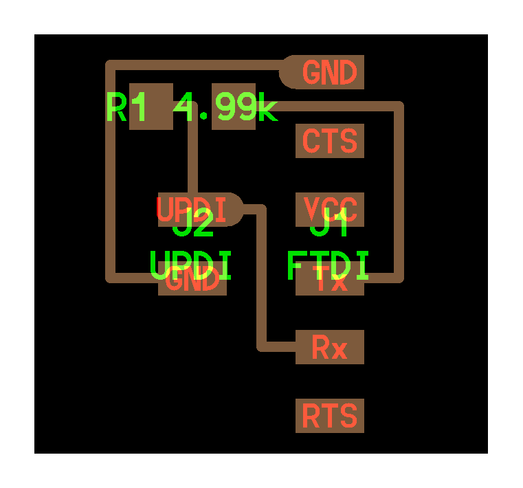
Before searching anyfurther, my instructor invite me to test first with another programmer to verify my board. I also finally found out I couldn’t program the ATtiny through UART but only with UDPI, so I needed to design a UART to UDPI adaptater. I make an adaptation of the one provided on the documentation. But I also made the mistake of designing it backward.


Even as my boards was rightfully alimented, i could manage to program it. I always had an error of communication with the UPDI. I checked the datasheets and prior years fabac students documentation.
I learned a lot through Tessel Renbrinks’ documentation. I compared the parameters I used in the IDE, I installed pyupdi, I changed programmers but it didn’t worked.
I also checked Hyejin Ahn’s page and Tamiya Yuichi’s page, but as I running very late for this week and the next one, I reported my investigation to more favorable times.
Class Archive
- SAMDino Kicad Schematics copy & PCB attempt
- Personal devboard Kicad Schematics & PCB
- Personal devboard SVG traces & interior
- Personal devboard RML traces & interior
- FTDI to UDPI adaptater Schematics & PCB
- FTDI to UDPI adaptater SVG traces & interior
- FTDI to UDPI adaptater RML traces & interior
Memes of the week :