3. Computer controlled cutting
Hero Shots

Assignment :
Group assignment:
- characterize your lasercutter’s focus, power, speed, rate, kerf, joint clearance and types
Individual assignment:
- cut something on the vinylcutter
- design, lasercut, and document a parametric construction kit, accounting for the lasercutter kerf, which can be assembled in multiple ways, and for extra credit include elements that aren’t flat
Group Working
For the group assignment, we agreed on tasks to realize and on the design of our models. You can find our group page here and this week group assignement here
Lasercutting test
I made on Inkscape the lasercutting test, inspired by the different tests available in our Lab.
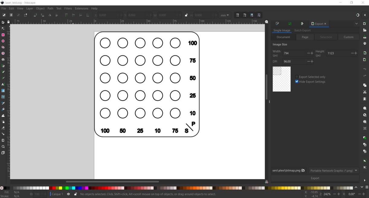
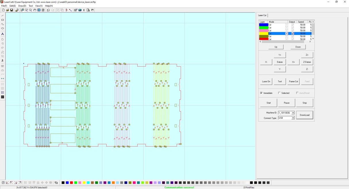
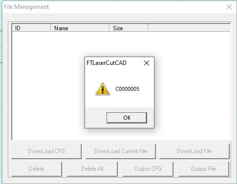
The machine used lasercut 6.1 software to run. It needs to read files as DXF, occuring a lot of troubles in conversion with more recent file types. Unfortunately, Lasercut couldn’t read my DXF file, and not knowing at this monent how to solve it, I decided to remake it directly with the Lasercut Software.
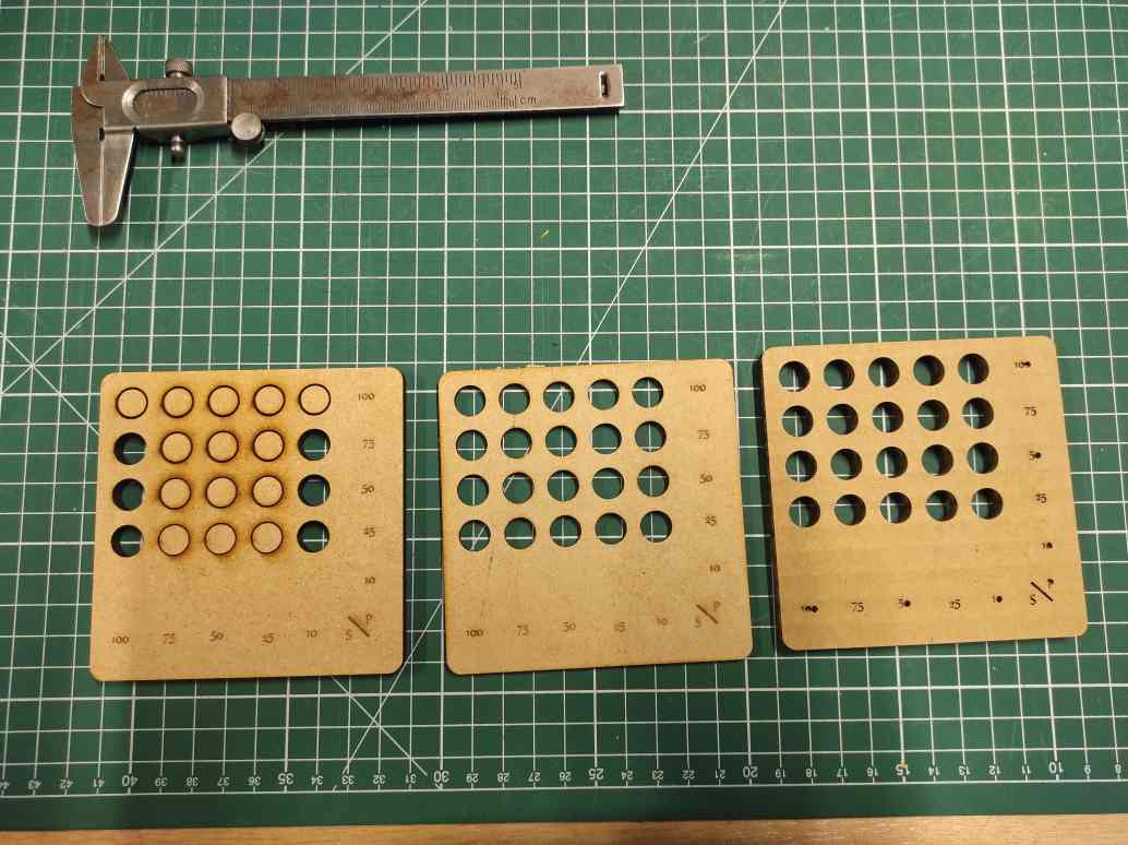
Lasercut software uses colors to differentiate the line. It realize the cutting in the order they appeared. The power and the speed of cutting or engraving can be set for each color.
The Lasercut Software was hardwork : each parameters change make to 30 seconds to apply, selecting a path don’t enlight the color corresponding making the more than 25 colors to check very difficult, and the 100mm/s speed go unexplicably slower than the 25mm/s.
I could make test on 3mm and 6mm MDF and on 6mm cardboard.
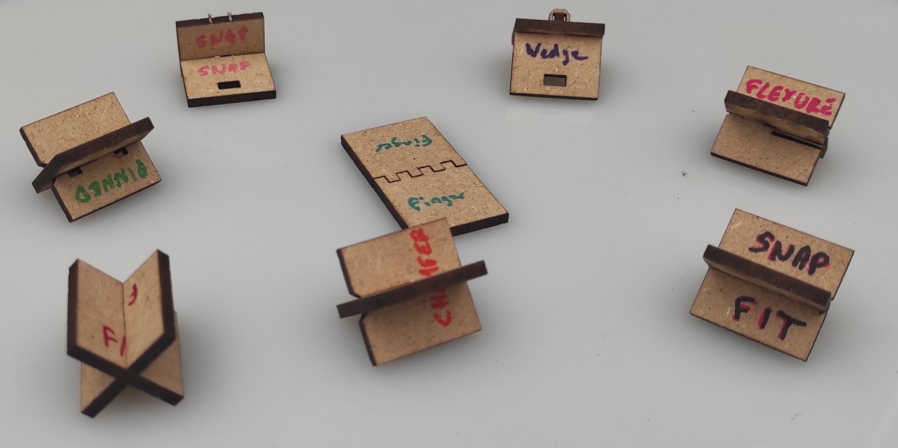
Joints types test
I also remade the joints examples provides in the course documenation in fusion. I tried to make it parametric, using fusion paramaters.

I made all the models in one sketch using formulas as measurement, and constrait to keep them in the right form.
Although, when i change parameters such as the material thickness, i couldn’t get everything to stay at the right place, probably because some constraints are missing or not pertinent. I need more exploration of that and I should certainly make several sketches to facilitate the process and test the parametrics on the go.
To prepare the file for the lasercut, i extruded all the joints, made a new sketch, use the projection tool on all the bodies and add the kerf radius as on offset.

Focus
I made the focus alignement, inspired by 2022 Agrilab students work.
I used a caliper to measure distance between a sheet of paper and the down edge of the tightening ring.
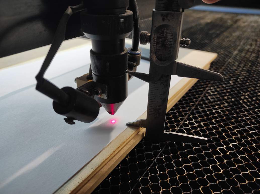
I made a series of point with a z modifier. I found the 50mm settings was the finest point on the paper and correspond to the autofocus setting.

Vinylcutting
Design
In order to test the vinylcutter, i decided to modify my lab mascot, the cow matching . I downloaded a png base model on my instructor Luc Hanneuse’s FabAcademy page and modified it with inkscape. As an amateur of lovecraftian tales and the Cthulhu myth, i decided to add tentacles and wings using Bezier curves tool to transform it as Cowthulhu.

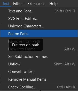
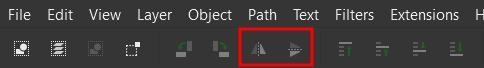
For adding the text in a circle shape, I first create a textbox and trace a circle path. Then I choose the “Put on path” tool in the “Text” Menu. Using, the mirror and rotations tool, I managed to place the text where i wanted.

I needed a second circle for the second part of the text.

To finish, I modified the path to make them non-visible.

Cutting
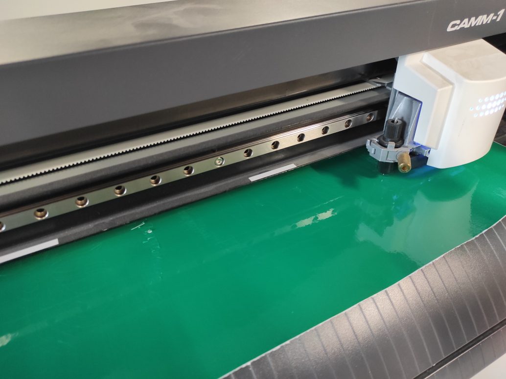
I used the Roland Camm-1 GS-24 Vinylcutter to cut my model.
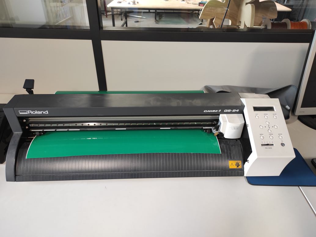
To charge it, the lever must be down.
The roll need to enter the most aligned way possible. The size can be adapt by moving the wheel as needed, preferentially under a white mark.
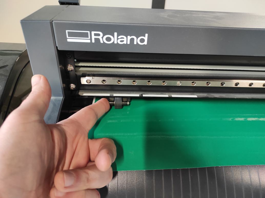
When the position is good, you can pull down the lever and valid the charging with the Enter button.

This vinylcutter uses an automatic level knive. The pression force can be set directly on the machine using the force button. 60gf is recommended for adhesive vinyl and 50gf for flex.
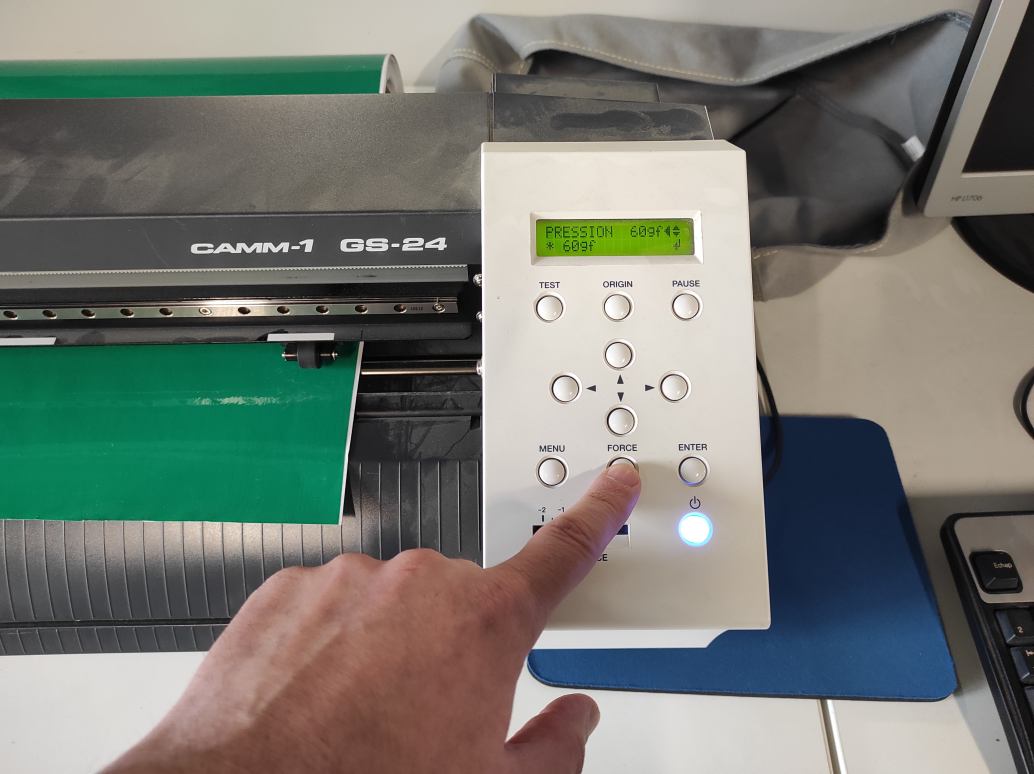
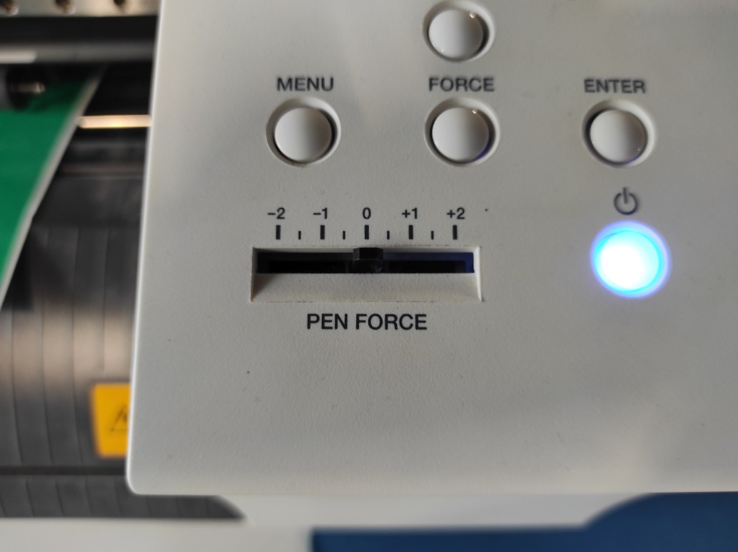
If needed, there is a possibility to slightly adjust the pen force on the go.
Before starting, the origin can/must be set using the arrows to move the pen, and maintaining the origin button to validate the position.
You can open your svg file in Inkscape.

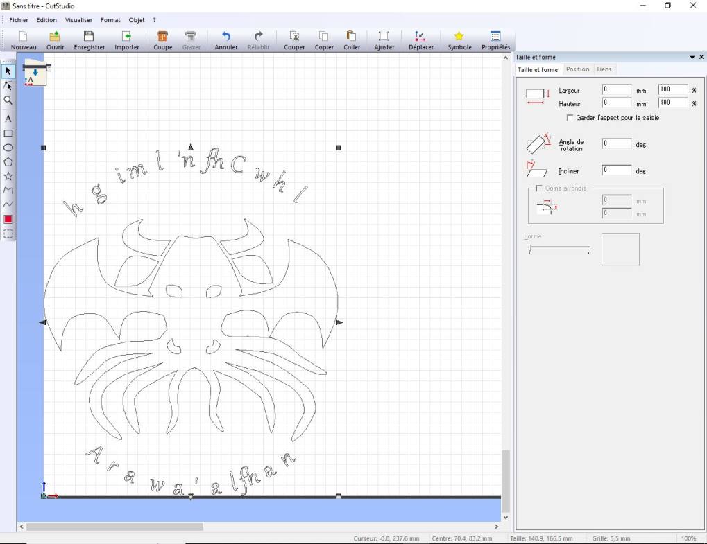
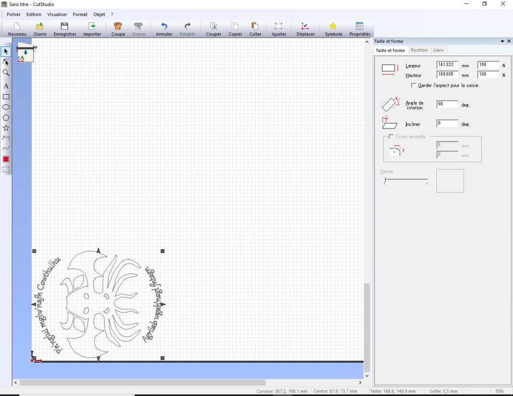
The SVG is exported to Cutstudio software with a plugin. You can open it through Plugin>Roland cut Studio>Open in CutStudio (or “mirror horizontal” for Flex)

Cut studio needs all the path to be grouped to open them but it didn’t recognize well the text, even if it was turned into paths. To resolve it, I had to juggle with the combine tool and group/degroup to get all the letters. I didn’t find a consistant way to do it but i maged to have it works. Then I rotate it for space management.
I choose to make an adhesive vinyl for my notebook.
I used the recommended configuration at 60gf pen force and standard speed (25m/s)
The motif was good but the text was a bit ripped. So I made another try reducing the pen force to 50 and the speed. This second realisation didn’t cut enough material and I moved the vinyl sheet so I couldn’t make a second pass.
The third try at 55 pen-force with 2 pass was a success so I could start the weeding.
The central was quite easy to weed, but i had a lot of work for the letter. I had to use tweezer, curved weeding tool and knive, letter by letter. Some of them detached and I had to replace it.


I had the same difficulties with the transfer media. Some letters didn’t want to stick on it or on the contrary didn’t want so stich on my support. I often had to grab them and replace them with the tweezer.
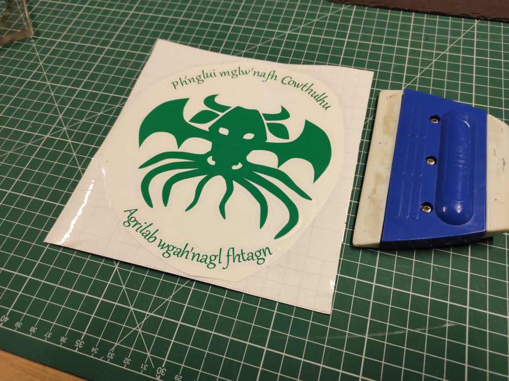
I finally made it and I’m quite satisfied of the results.
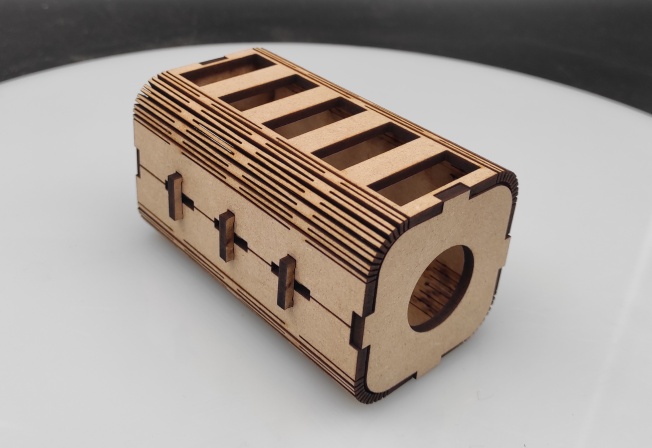
Lasercutting
Design
I wanted to try living hinges patterns. I searched for tutorial and followed this one.
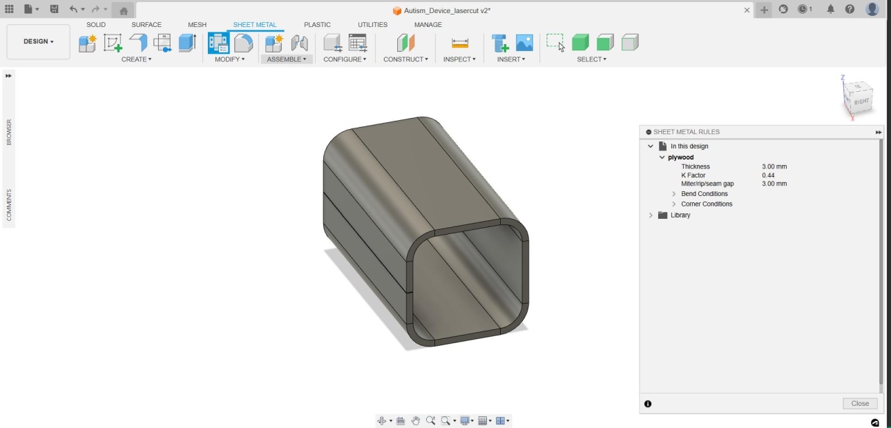
I decided to make a plywood model of my final project to see the size. I’m aware that living hinge aren’t strong enough for something that will be manipulated a lot. I have rebuilt my model on fusion using metal sheet.
I set parameters for the material thickness, tolerance and the kerf we have determined for the group assignement.
I started with a profile large enough for the future switch for the length I choose about my palm size.
I defined sheet metal rules in the sheet metal menu then create a flange from my sketch.
Then, I create flate pattern and start designing the hinge.
I needed to add some parameters with formulas to calcule the amount of line needed and the space beteween them.

Using multiple sketches, to avoid too many calculation from the software, I create rectangular patterns for the first hinge with projections, then another rectangular pattern for the three other hinges.

I finally added cutting and bodies to complete my 3D model. I cchoose to add a hole large enough to push a button inside it. It will permit to avoid unattended push on it.

I first used finger joints and tried to design a closing system but it wasn’t working very well. I finally change the closing systeme for simple staple-like clips.
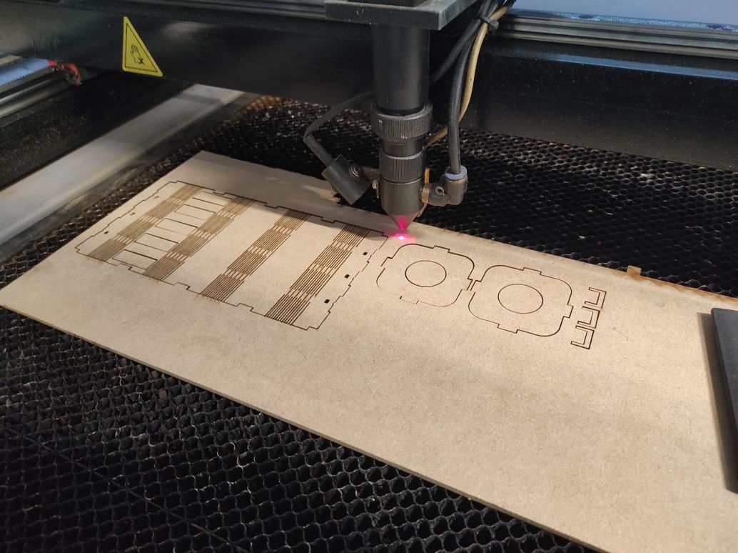
Cutting
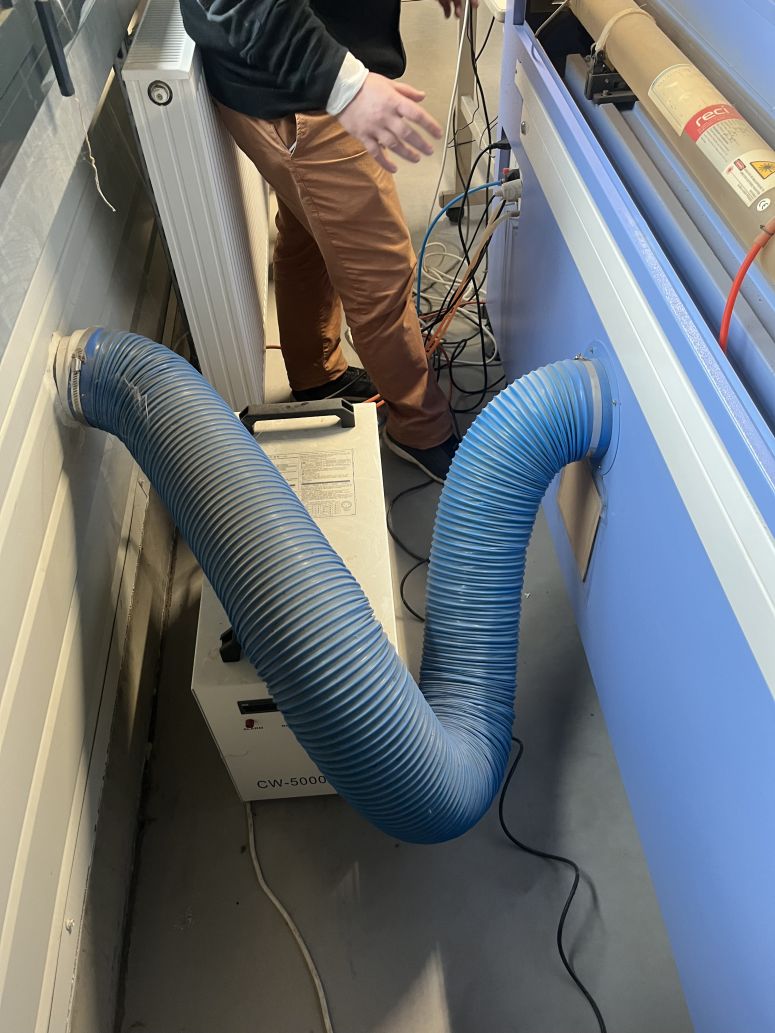
The lasercutter used at Agrilab is a MLlaser ML-W1290 150W. Its cutting surface is 1200*900mm.
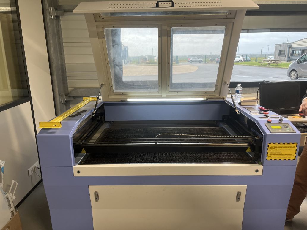
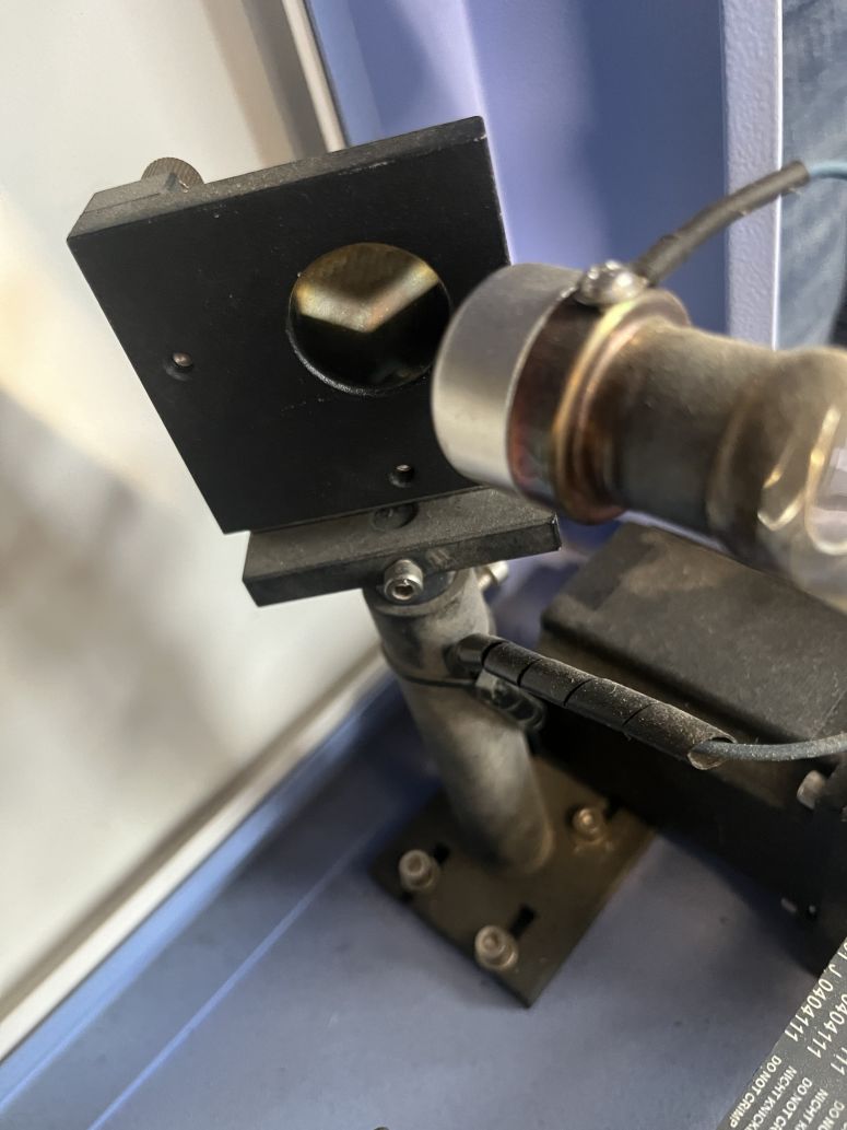
The CO2 laser tube at its back send light to 3 mirrors then trough a lens to focalize the power to a point through the material to cut by burning it.

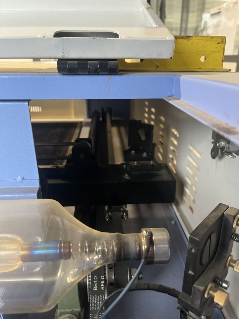
The tube is cooled with a watercooling system and the smokes are extractyed to the outside through a venting machine.
The machine used lasercut 6.1 software to run. It needs to read files as DXF, occuring a lot of troubles in conversion with more recent file types.
For my model, I had to use multiple DXF files as it was difficult for the software to interpret multiple path. I had to keep it the most simple as possible. I used projection of my final model to avoid DXF messing up the paths. The counterpart was that everytime I wanted to implement changes or improvement the projection links broke and the sketche needed to be remade. On those last sketches, i added an offset of 0.125mm corresponding the radius of the kerf measured by my co-student. Lasercut software uses colors to differentiate the line. It realize the cutting in the order they appeared. The power and the speed of cutting or engraving can be set for each color. For this model, I only used 50% power at 50mm/s in cutting as it appears to be one of the most efficient power/speed rate for a 3mm MDF when I tested it for our group assignement.
Also, the communication between the machine and the software sometimes broke. The only way to repair it is to reboot the computer.
My two first lasercut broke before I could take a picture. But somehow, i needed to re-cut it as I forgot to remove some hinge cuts that conflicted with the switches cuts for the first one, and to add the kerf offset for the second one. Also, my closing system was completely inefficient, so i simplified it.
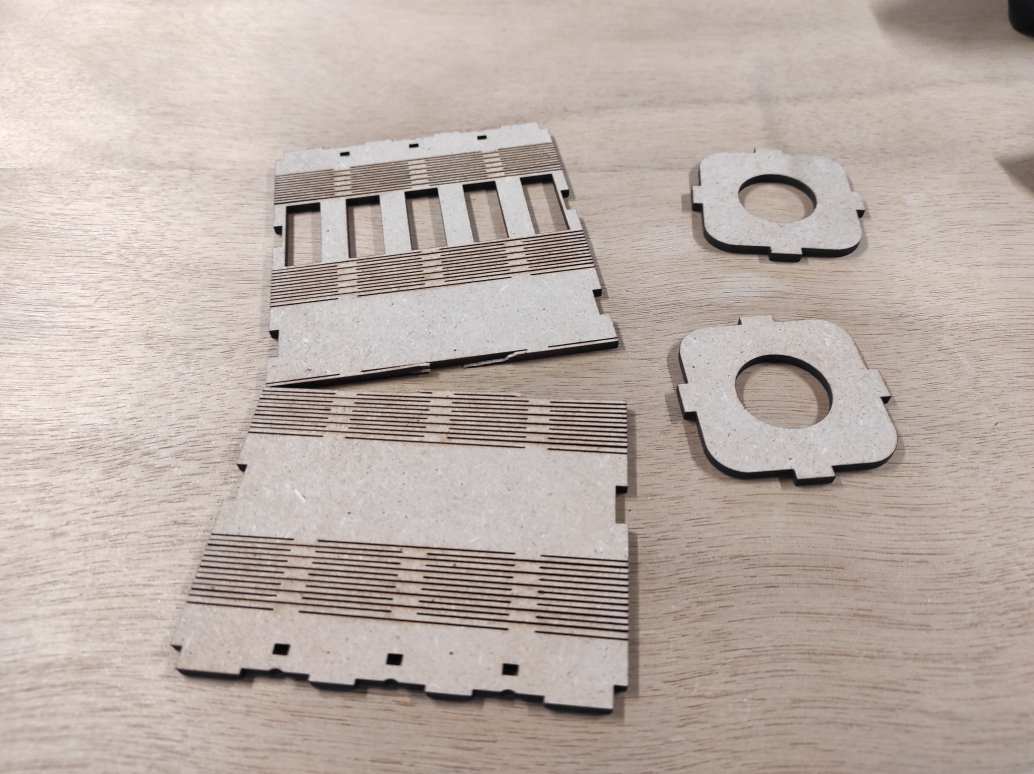
On my third attempt, I could finally make a nice lasercut and assemble it.
The hinges don’t completely fit, probably because the pattern make it too loose.

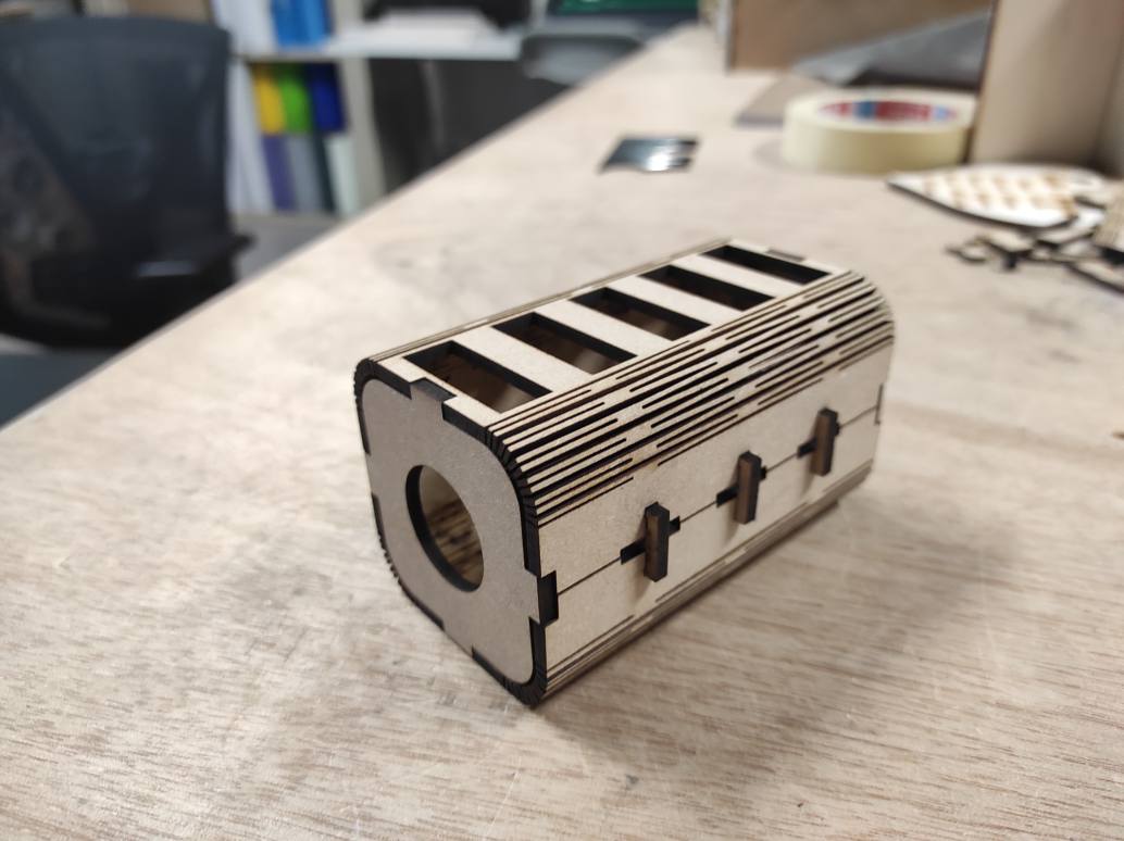
The size could be a bit longer to facilitate manipulation between the two hands and i’d like it to be thinner to handed it more easily.

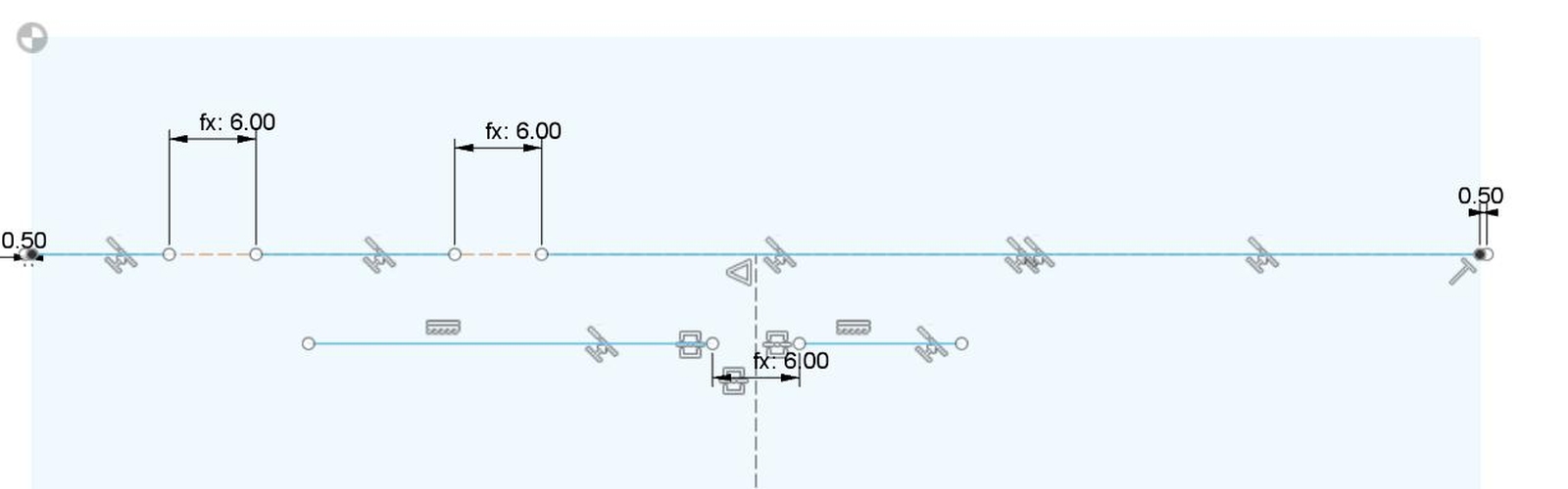
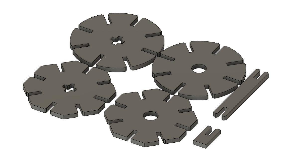
Parametric design
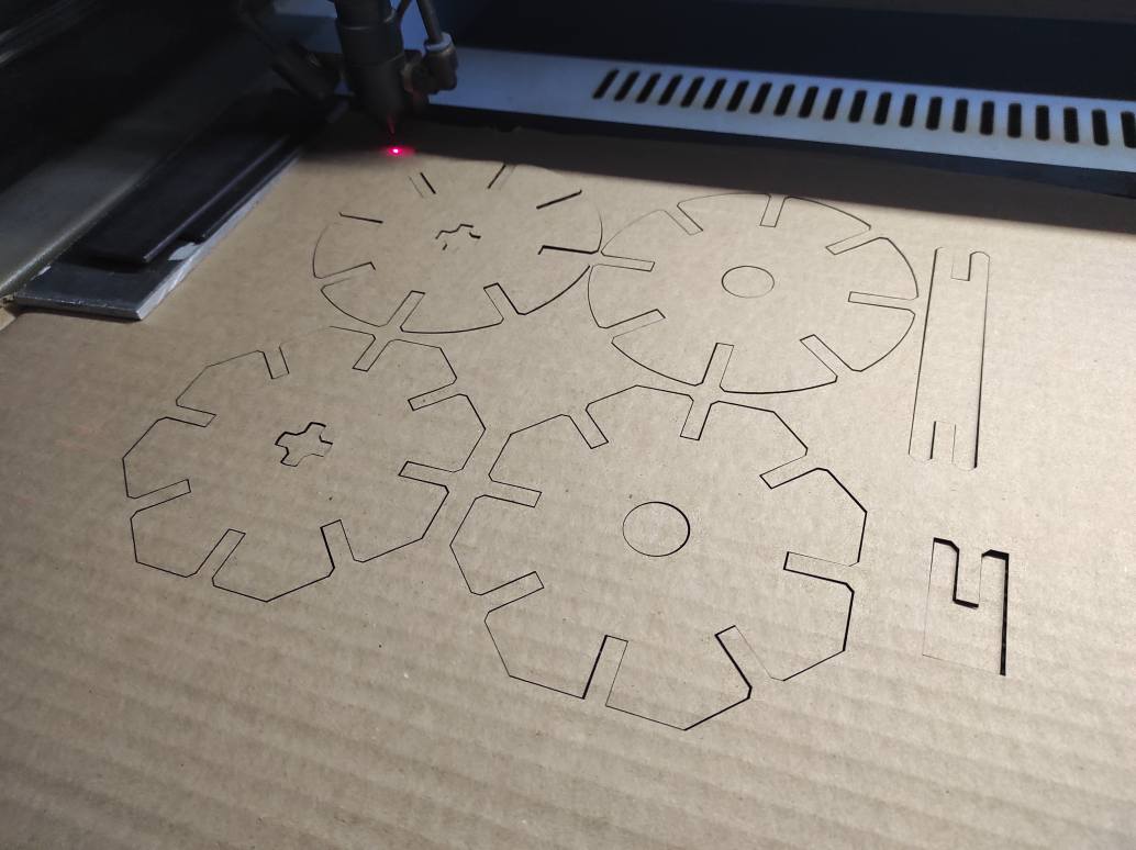
To complete my assignment, I created a parametric design for a construction kit using Fusion 360.
From a unique sketch, I made 4 kind of pieces (octogon or round, with crossed or circle center)

All dimensions are relative to the material thickness, except for the kerf.
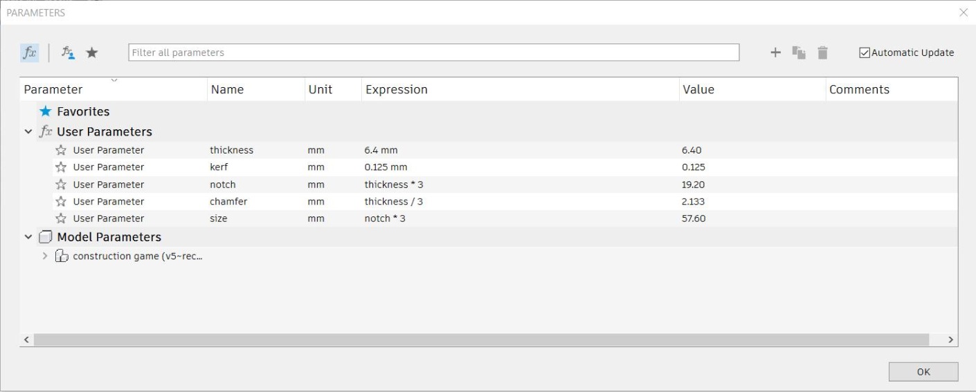
I added some pieces to make axes or clip. Then I made an offset of the kerf an all the side surface, including the holes.
I cutted the design on a cardboard.
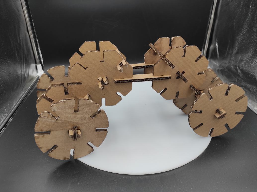
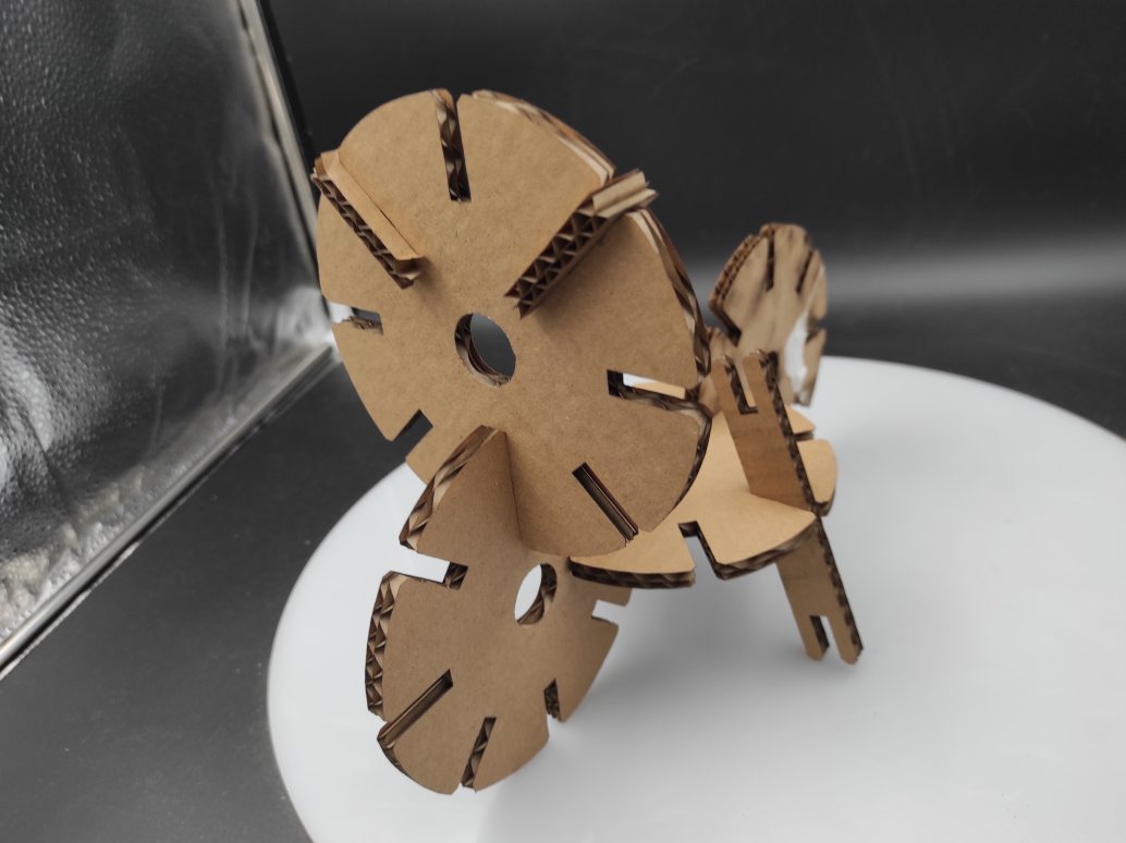
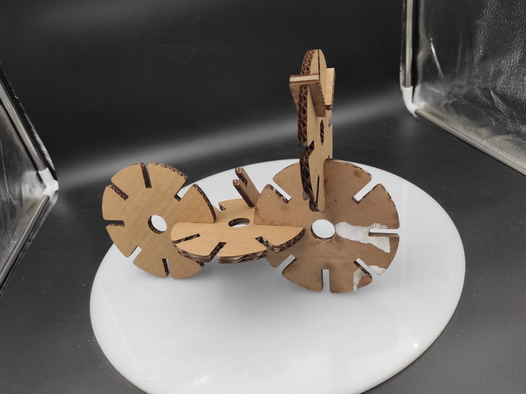
I could make some assembly, like a cart or a motorcycle.

My files
- Lasercut test Inkscape file
- Joints type models F3D
- Joints type models DXF
- Cowthulhu Vinylcutter SVG File
- Mood/Interaction acceptance device wood prototype F3D
- Mood/Interaction acceptance device wood prototype DXF 1, DXF 2, DXF 3
- Conctruction Kit
Impressions of the week
As usual now, not much time for a lot to experiment. I took nearly an entire day for my vinylcutting and weeding but I really enjoyed it. I feel more confident with Inkscape too. Concerning Fusion, I learned to use a part of the metal sheet tools I never touched before. I wanted to try the hinge but i don’t feel confident to re-use it later without a tutorial. If I had more time, I would have spend it trying several settings for the hinge patterns maybe making a workbench of it. I would have appreciated to explore more type of pattern too, as I imagined some pushing or sliding system.
For my final project, I don’t think I will use the model I created this week, beacuse it’s too fragile and absolutely not ergonomic. Anyway, it helps me defining more precisely what I need : a shape more elongated to facilitate manipulation, a more flexible material like rubber or silicone, a reccessed button to avoid unattended push.