4. Electronics production
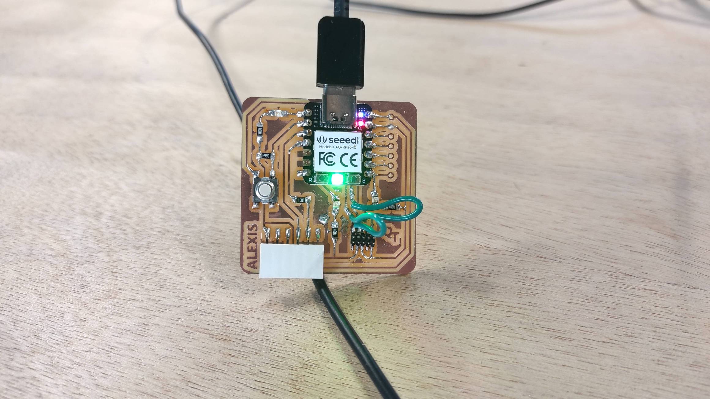
Hero Shot
Assignment :
Group assignment:
- characterize the design rules for your in-house PCB production process
- send a PCB out to a board house
Individual assignment:
- make and test a microcontroller development board
- extra-credit : personnalize the board
- extra credit: make it with another process
Group work
You can find our group page here and this week group assignement here
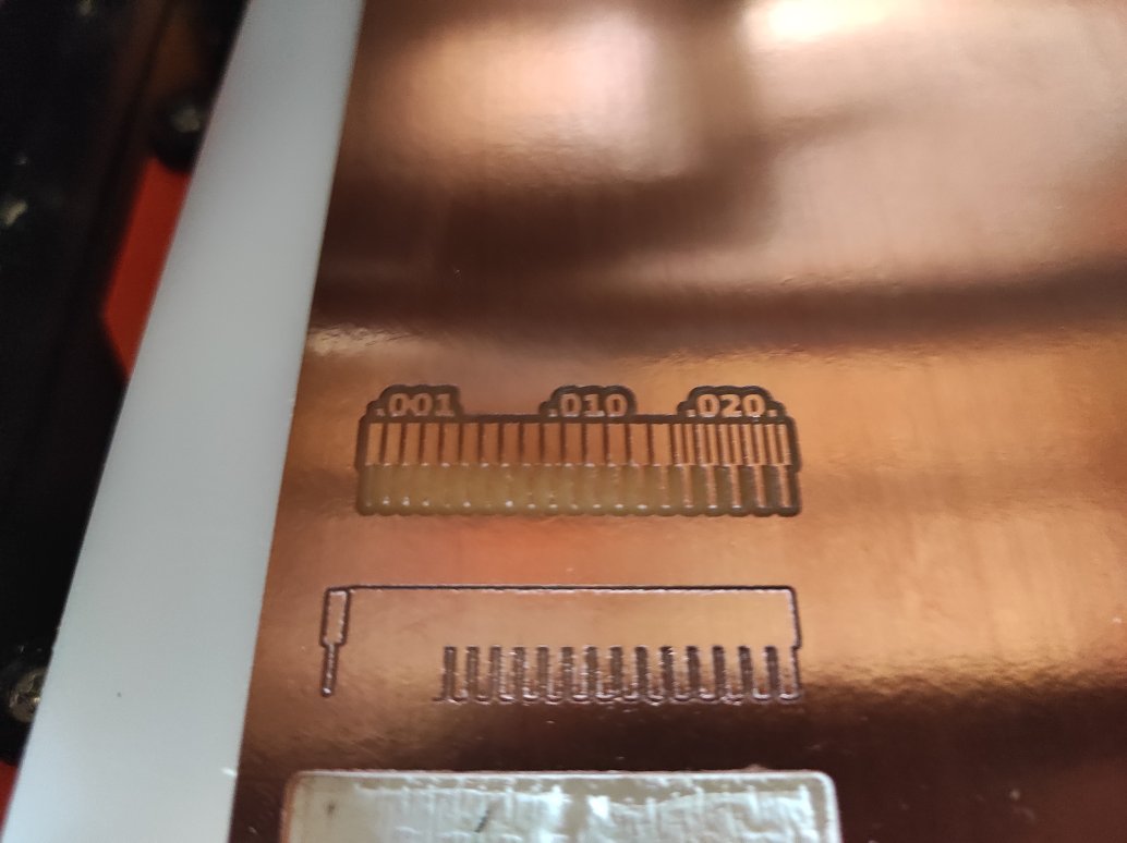
To characterize the design rules for our in-house PCB production process, we decided to try different end mills on our Roland SRM-20.
Preparing files
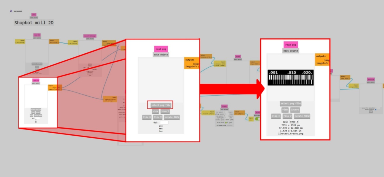
Getting the traces and the interior linetest PNG files from the course documentation, we used mods project.
At first, youve to right-clicked to open the menu, then choose programs > open program and finally choose the milling machine and the program corresponding. For us, it was the Roland SM-20 mill 2D.

It opens a big tree where you need to enter the settings to create your work file.

We will need two files, one for the traces and one for the cutting, cause we don’t use the same end mill.
First, you need to upload a SVG or a PNG of your circuit path.
Then you add the end mill properties for creating the path in the end mill Raster 2D box. We use a 0.4 mm flat end mill with a cut depth of 0.1 mm. The offset is set at 4 with a stepover of 0.5, meaning that the end mill will make 4 times the traces around the sketch if it has the space for it. You also need to add the milling machine properties, the speed of movement, here set as 1.5 and the origin. The job height and home can be let as it is.
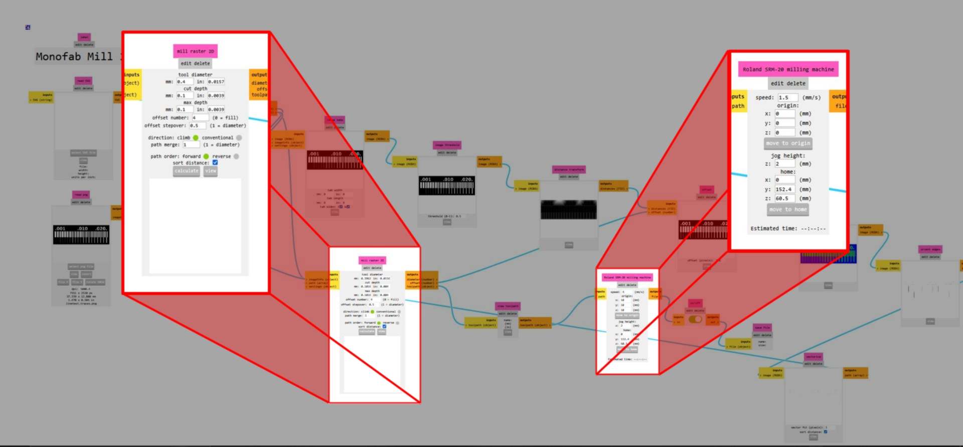
Once the parameters are set, you can click calculate under the mill raster 2D box. It will automatically download the file in the right format (RML for for this machine).

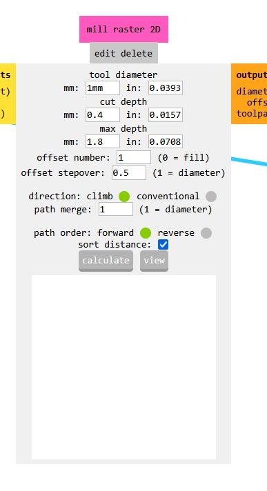
Use the same process for the interior : - Import the PNG file, - add the parameters : To cut the PCB, we use a 1 mm flat end mill, with a cut-depth of the 0.4 mm to a max depth of 1.8 mm (the pcb’s thickness is 1.5 mm). The offset is set to 1. The step is not taken into account in this case. The speed can be increased to 2.
Preparing machine
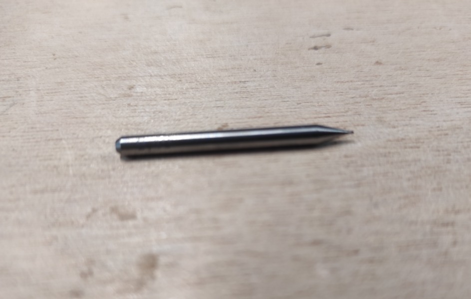
As described above, we use a Roland SM-20 milling machine with, for the first test, a 0.4 mm flat end mill.


Fisrt, the Copper Clad Laminate (CCL) has to be fixed on the sacrificial layer with double-sided tape. This time, the CCL was already fixed by our instructor for the exemple.
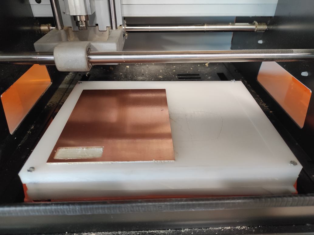
The end mill has to be screwed in the collet.

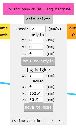
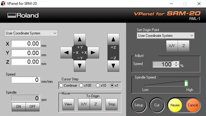
Using the machine’s dedicated software (Vpanel) controls, the end mill is placed over a chosen origin. You can choose the movement step : continue, x100 (1mm), x10 (0.1mm) or x1 (0.01mm).

You can validate the position by hitting the XY Origin on the right side of the panel. The position X and Y now turn to 0.

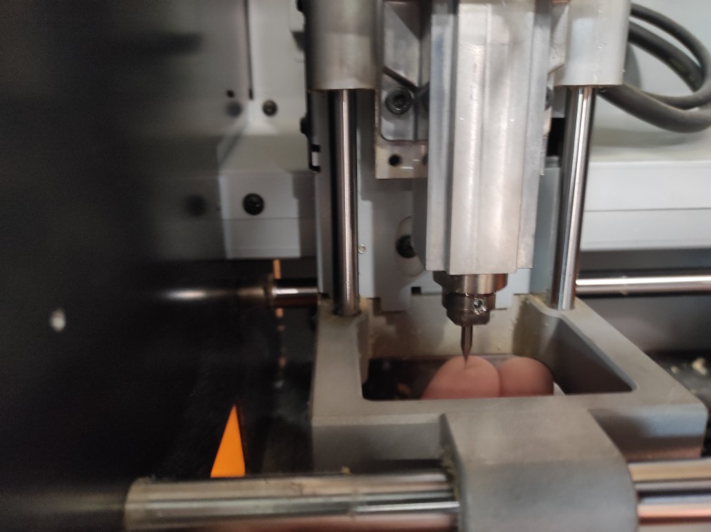
Then you have to set the Z origin. To do so, you have to approach the end mill near the surface of the CCL, then unscrew the collet to make the end mill slip a little (controlled by touching it) till the surface.

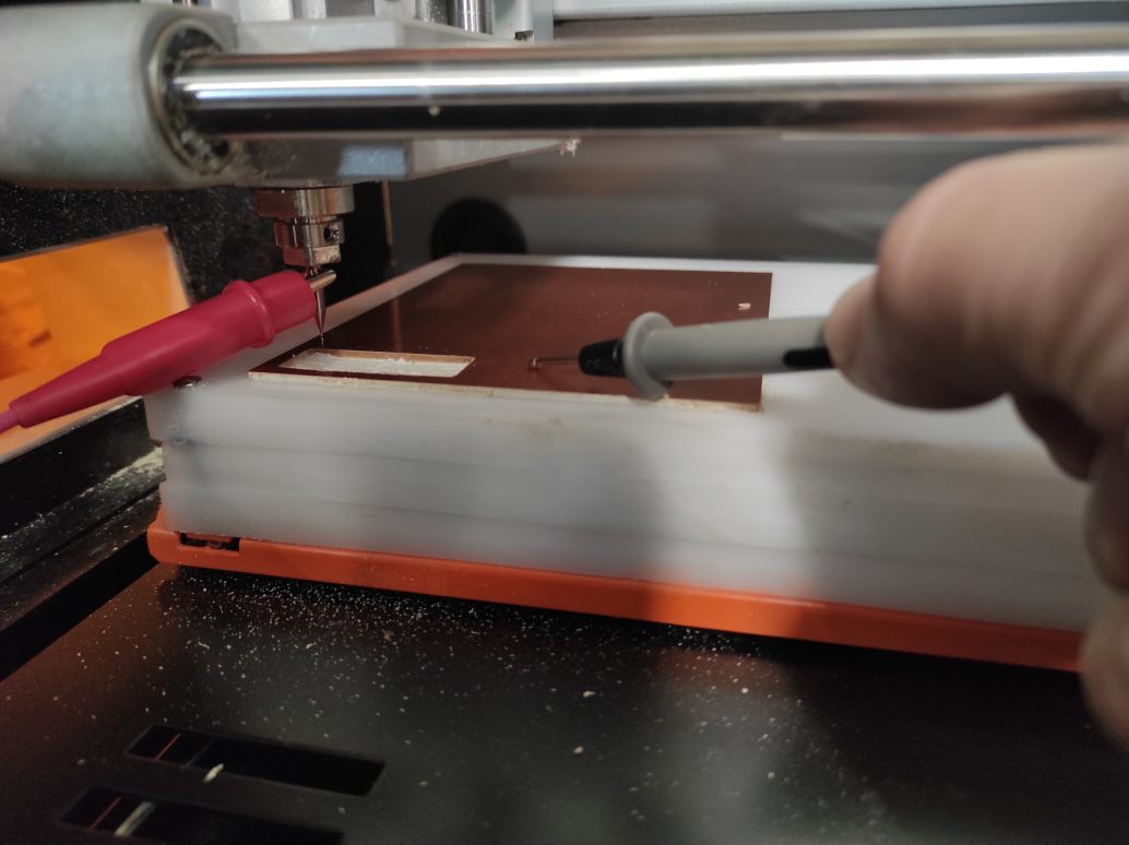
You can screw the collet again and verify the contact between the end mill and the CCL with a multimeter and the continuity test fonction. To do so, put a contact on the mill and the other on the CCL. The multimeter should beep if contact is made. If not you can approach step by step the end mill with the x1 step until you hear a beep. This technique is called probing.

Finally, you can validate the Z origin by hitting the button on the right side of the Vpanel software. The Z coordinates turne to 0.
Importing Files
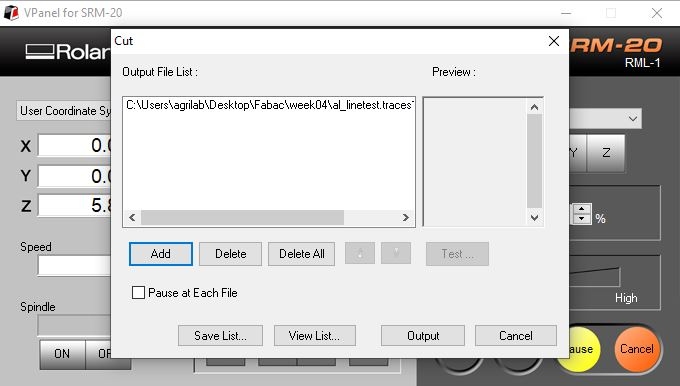
You can import your RML file by hitting the cut button. It will open a new window with the files currently in the machine as en “Output File List”.
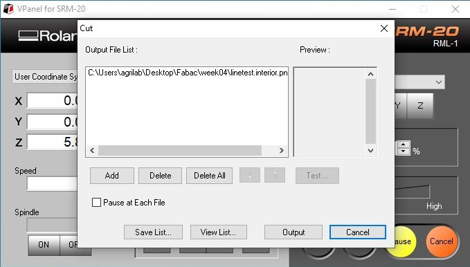
You should delete all the files then add the file you want to mill. You can now see your file in the output file list. If you hit the output button, the machine will start milling

During the milling you can check the position, the speed and the spindle, and eventually adjust the speed on the right side of the panel.

Once the traces are done, you have to change the end mill, reset the Z origin with the new end mill (don’t touch the XY origin !), and change the output file on Vpanel.
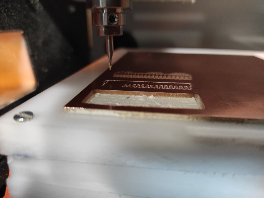
Milling
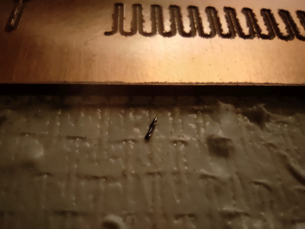
With the 0.4 Flat End mill at 1.5 mm/s speed, the first try broke the end mill probably because of a bad Z origin setting even if we used the multimeter technnique.
The second try worked better. So we can now reset the Z origin to make the cutting with the 1mm end mill.
The cutting finished without trouble. A bit of tape gripped around the end mill and need to be cleaned.

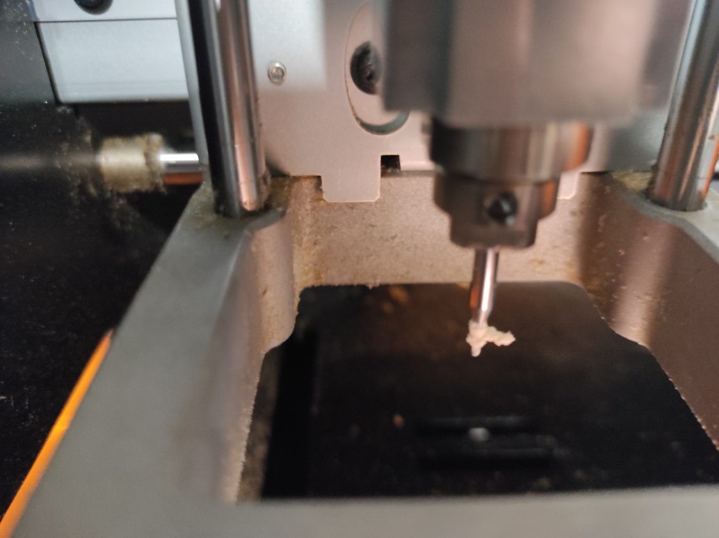
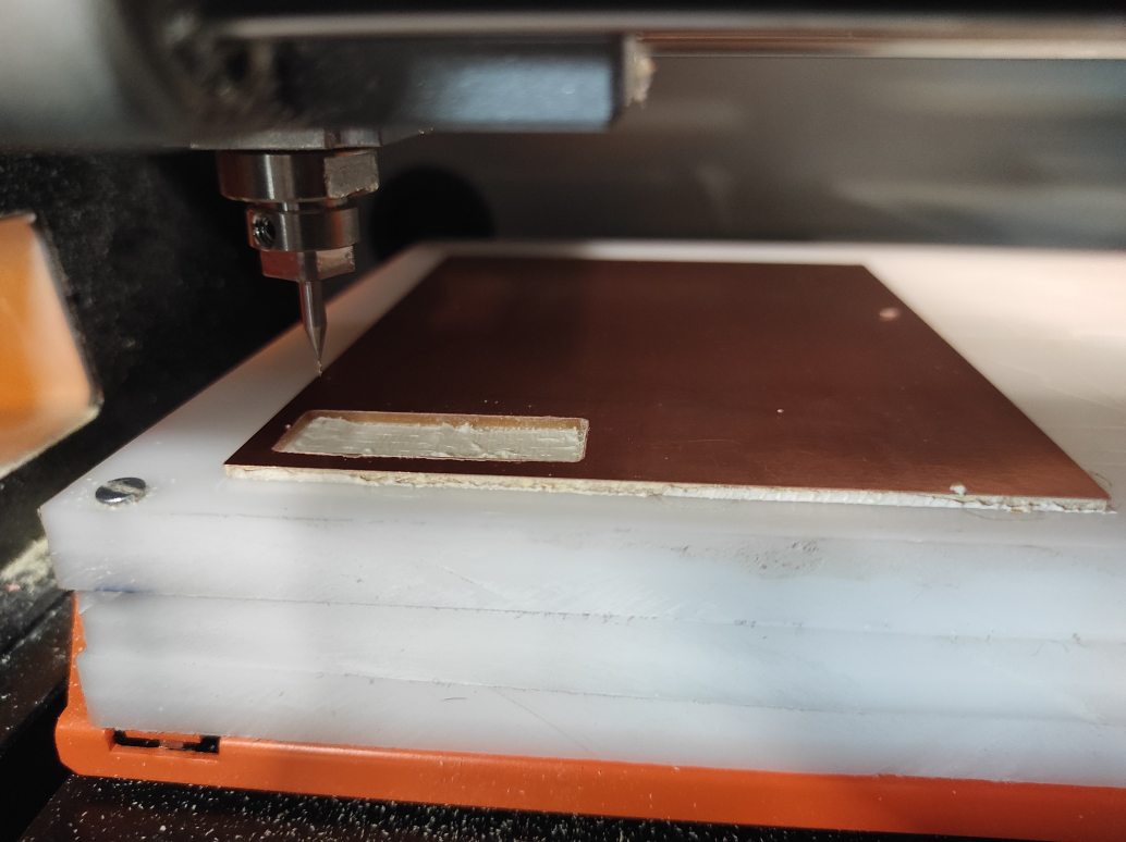
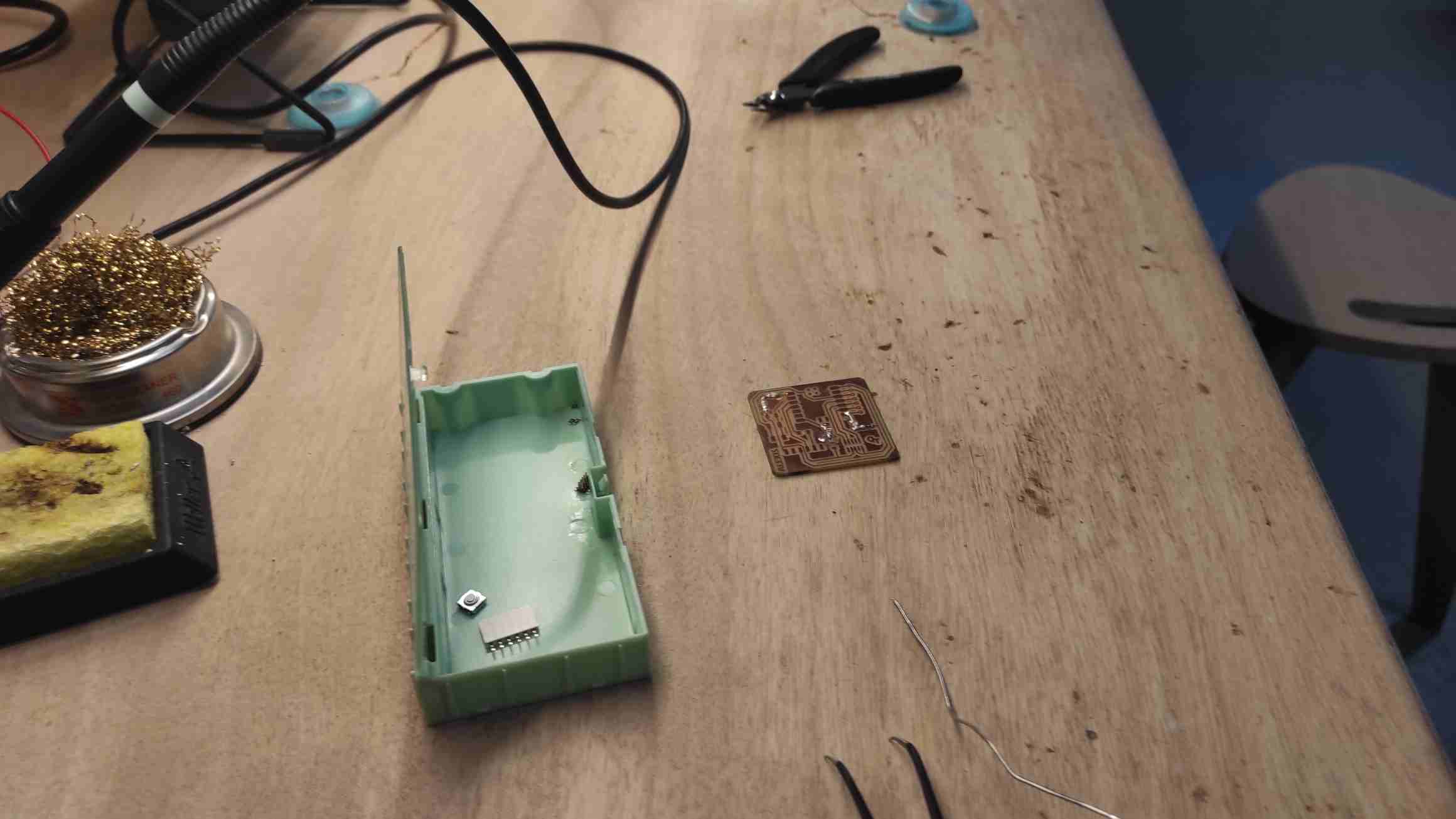
The test need to be took off using a spatula. The Results is quite good with this parameters.


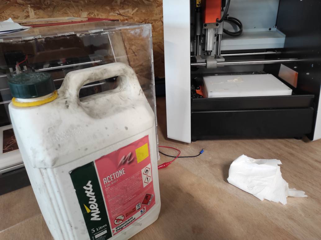
Taking off the rest of the CCL was difficult because of the double-sided tape being too sticky. We have to clean the different parts with acetone.

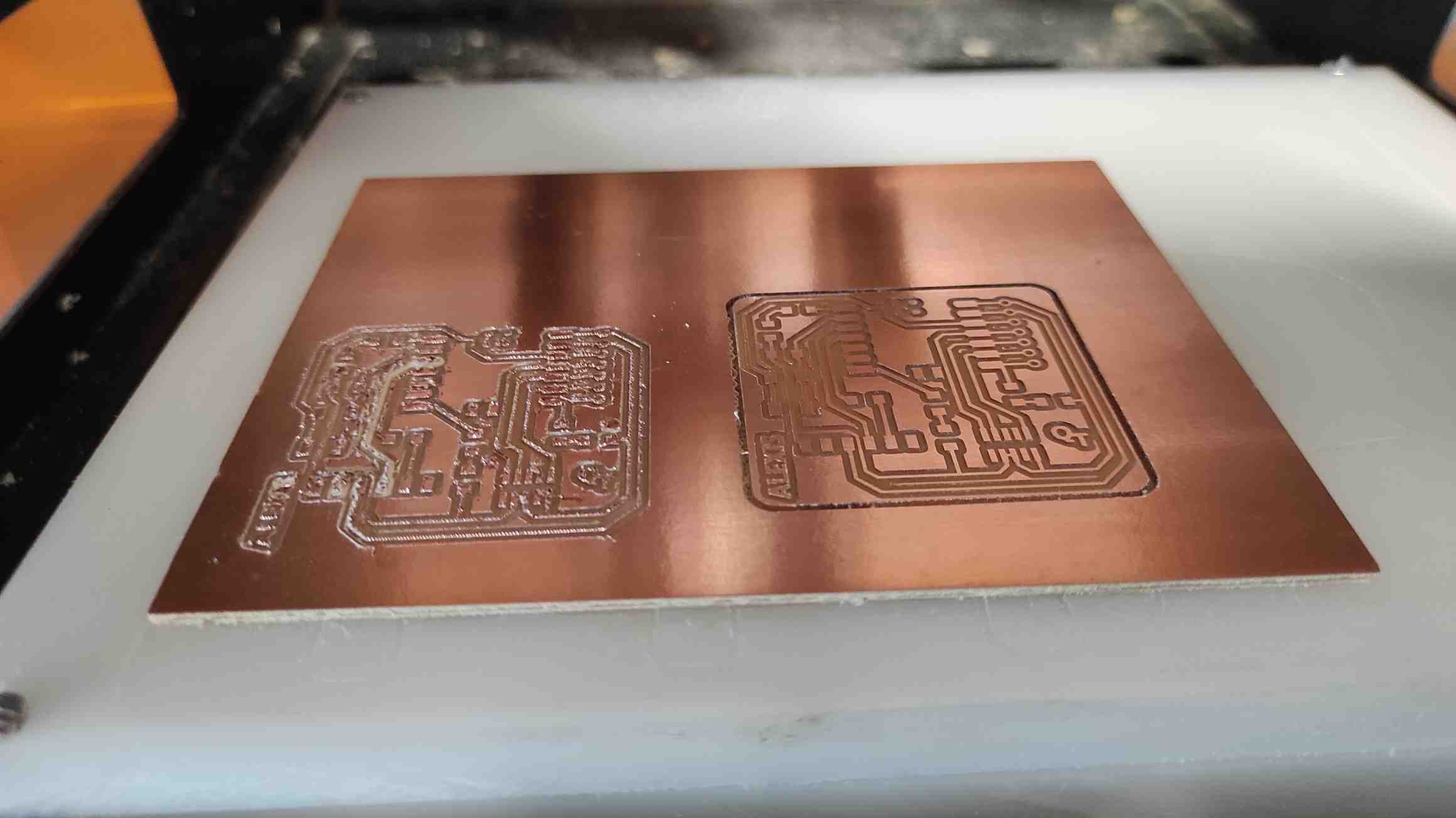
Test results
After testing different end mills, we decided to make our own PCB, with the L2SA 0.4 Flat End mill at 1.5 mm/s speed.
Individual Assignment
Files preparation
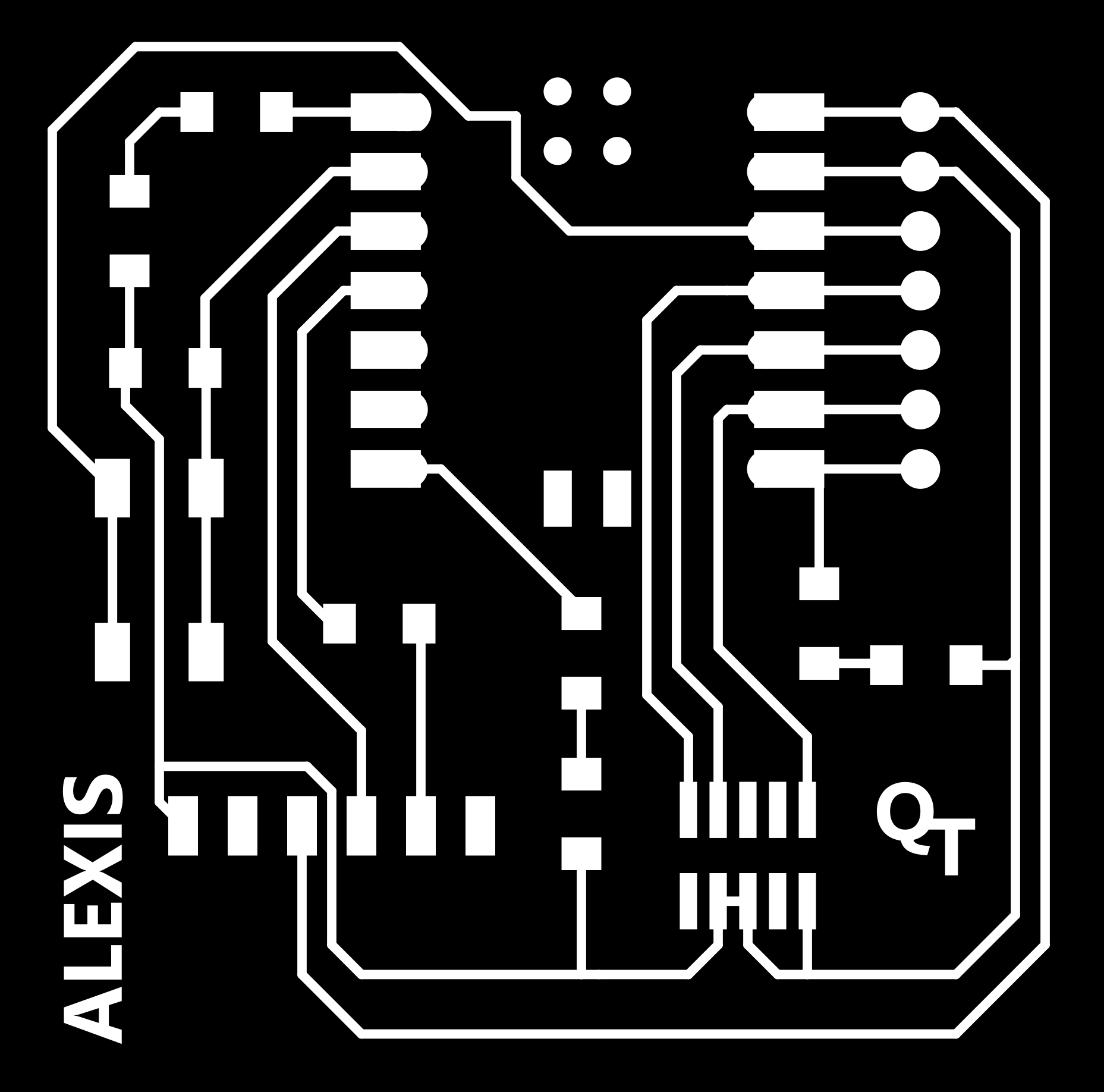
As suggested, I downloaded the PNGs for the Quentorres Board. With krita, I modified a bit the traces, adding my name on it. The same way, we did the end mill tests, I used mods to create the RML files needed for the Roland SRM-20 milling machines.
Using a 0.4mm flat end mill, I used the same parameters as the test ones.
For the drills, we had to find cheats because mods hadn’t generate path with the 1mm tool dimension parameter we should have used. Probably because of imperial system versus metric system, we had to decrease the dimension to 0.8 mm to generate the tool path.
For the interior, I keep the 1mm parameters.
Milling
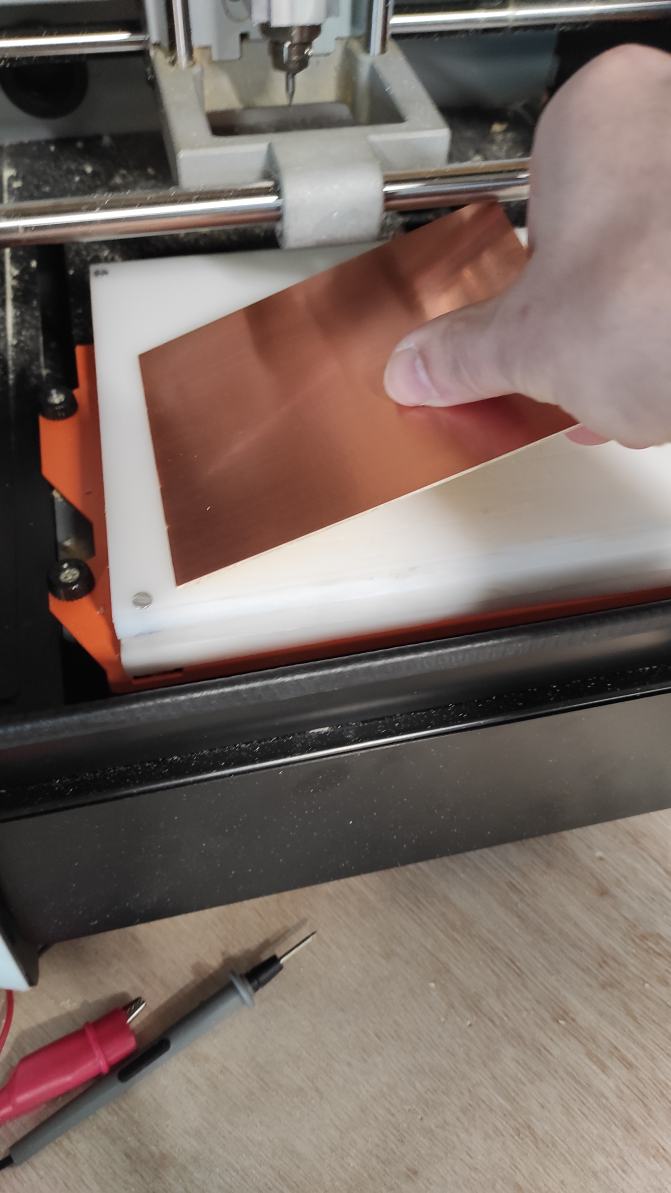
For this milling, I used FR1 CCL. I choose another doublesided tape less sticky to avoid breaking the board while untaping it. I took care of not making bubbles between the tape and the CCL nor with the sacrifial layer.

The traces milling was really messy at the first try. I think I forgot to validate the Z origin after the probing, so the milling machine use the origin memorized before. The traces are too deep and much copper has been torn off from the CCL. Plus, the end mill has been worn out.
video speed up x150
Paying more attention, I made a second try after an end mill change. This time the result was satisfactory.
video speed up x150
The drilling and the interior cutting worked with no troubles.
The tape used allowed for easier removal of the PCB than during testing, while still holding it securely during milling.
Soldering
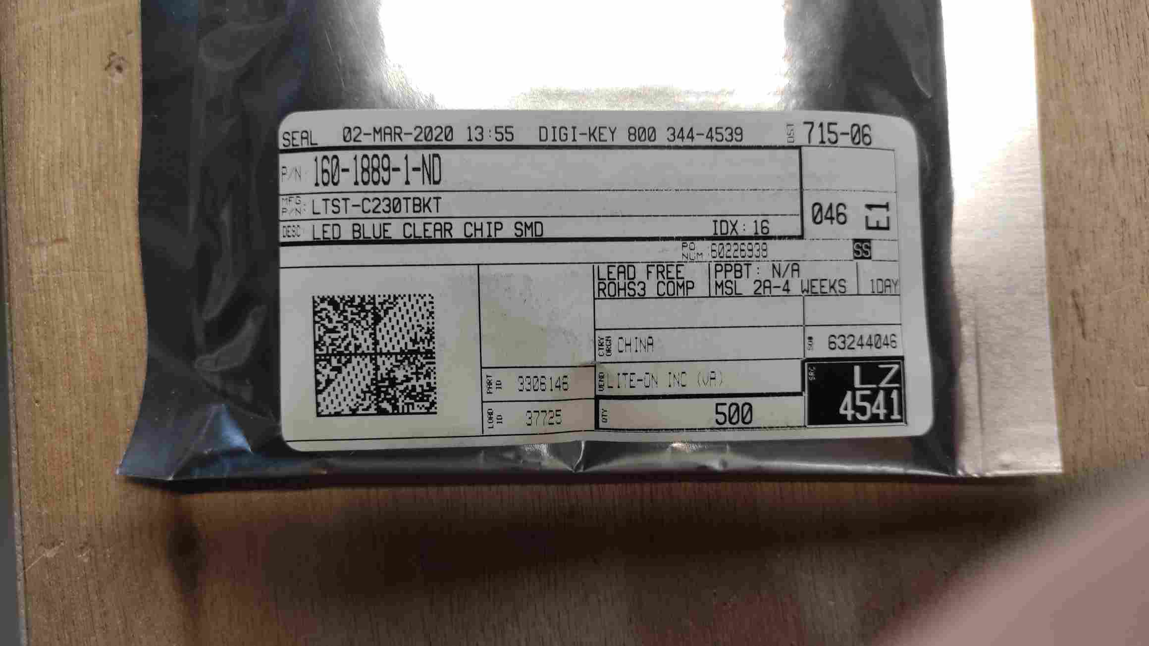
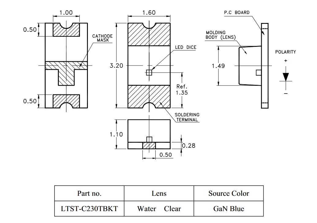
One of my co-students prepared boxes with all the components recquired for the PCB soldering. First, I verified the references and the positionnning.
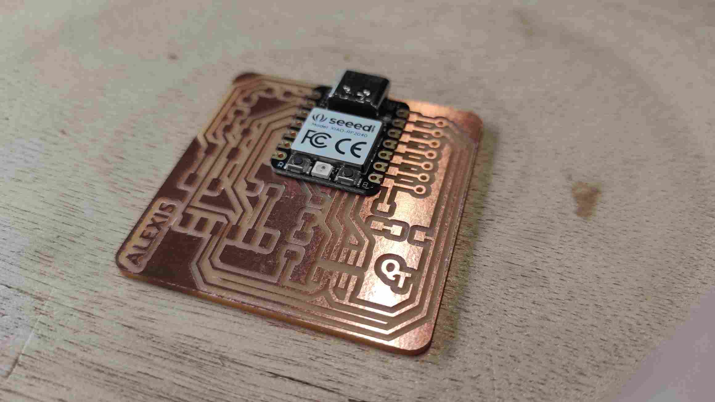
I double-checked the orientation of the LED cause the marks wasn’t the same as the one on the git documentation.
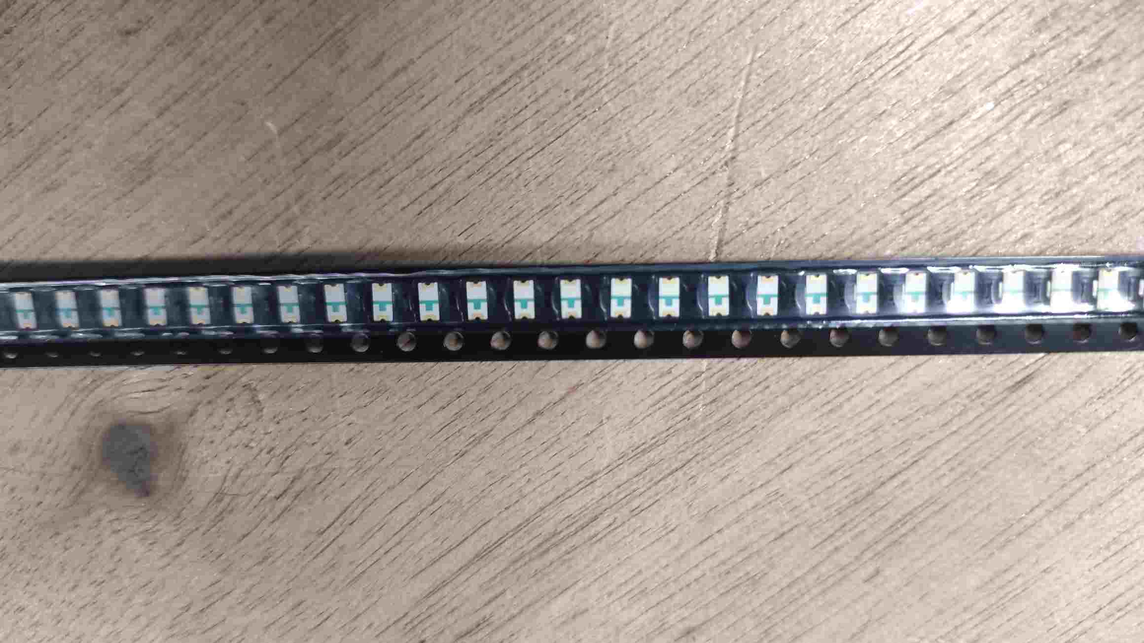
I started soldering the LED then the resistors as it feels more difficult to do due to their size. I used a tweezer to place the components hoping not shaking too much.

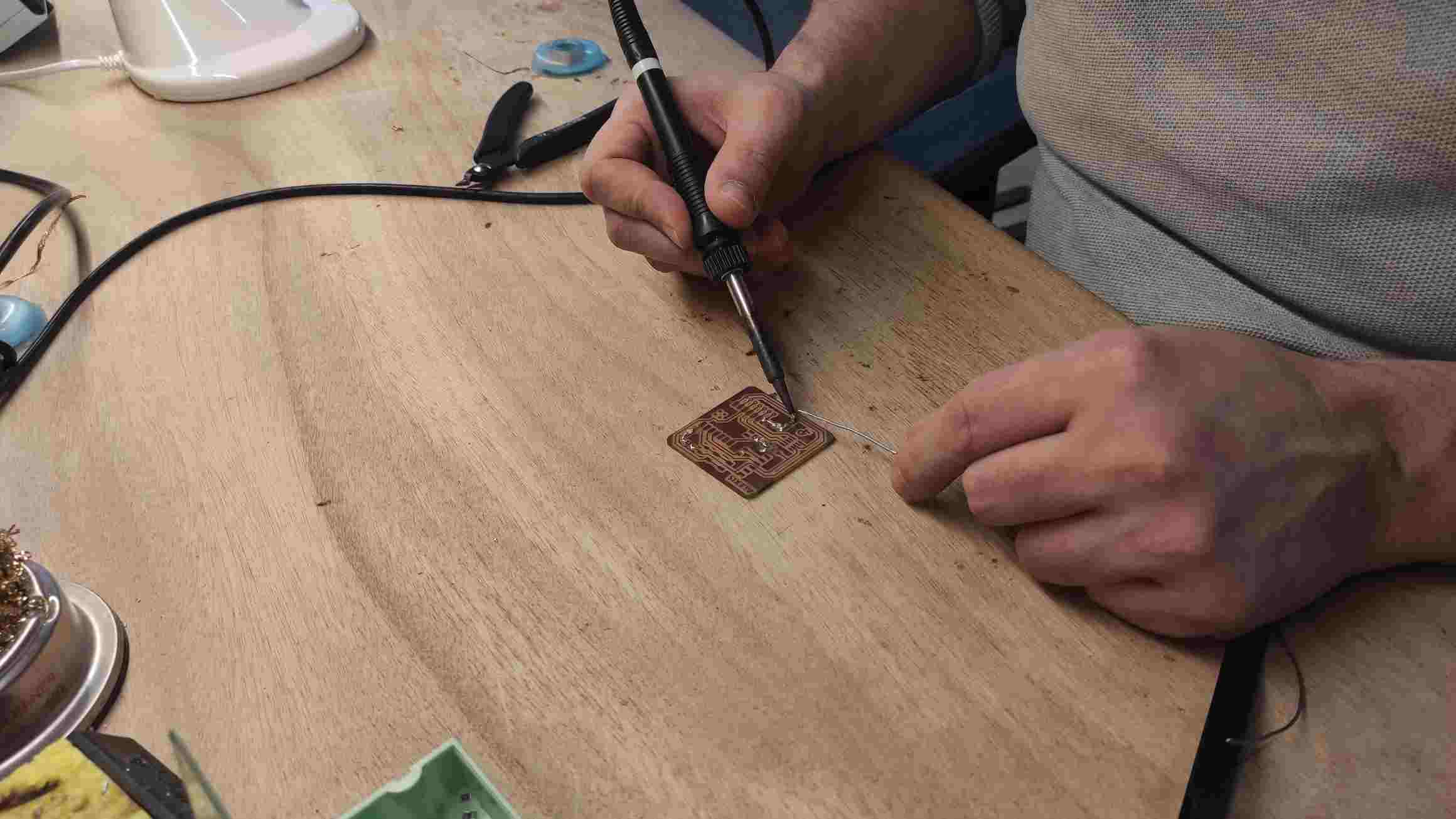 I hadn’t touch a soldering iron since middle school and I remembered this ol’time bad memories. Just like in the past, I had difficulties to make precise gestures, using the good amount of tin, and coordinates between the tweezer, the tin wire, the iron and the CCL. Often the components go away as I heat the tin, spreading it as bridges.
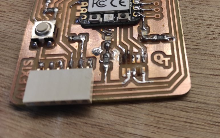
First part was kinda alright, not really clean but connecting as needed.
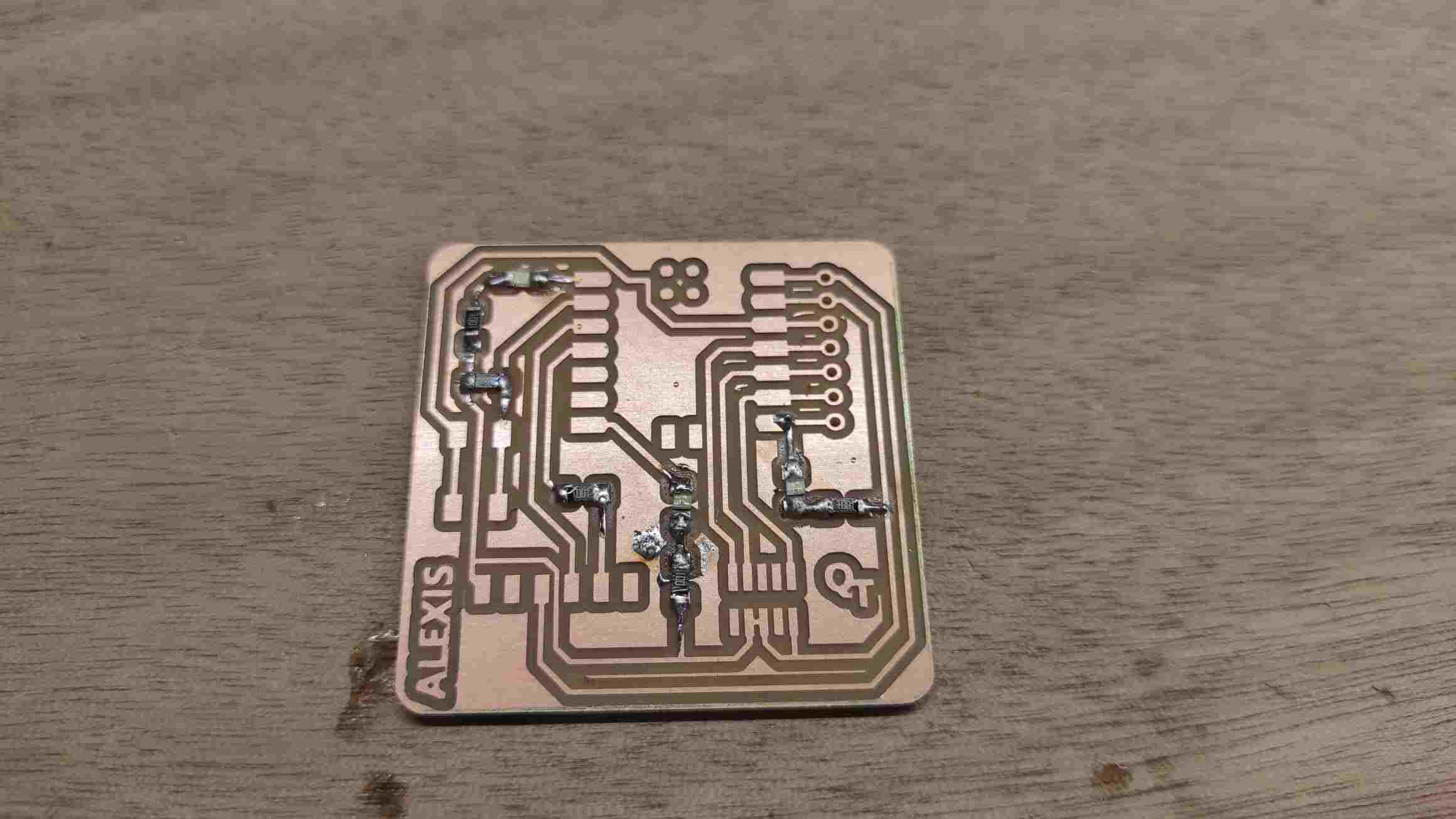
Last component was the vertical SMT header, and it goes really messy.
I used a first mechanical connection to place the component but when I putted it on, it spreaded tin over pins and uner the component. I took a lot of time trying to desolder that with braid and pump but it ended with some copper torned off and burned.
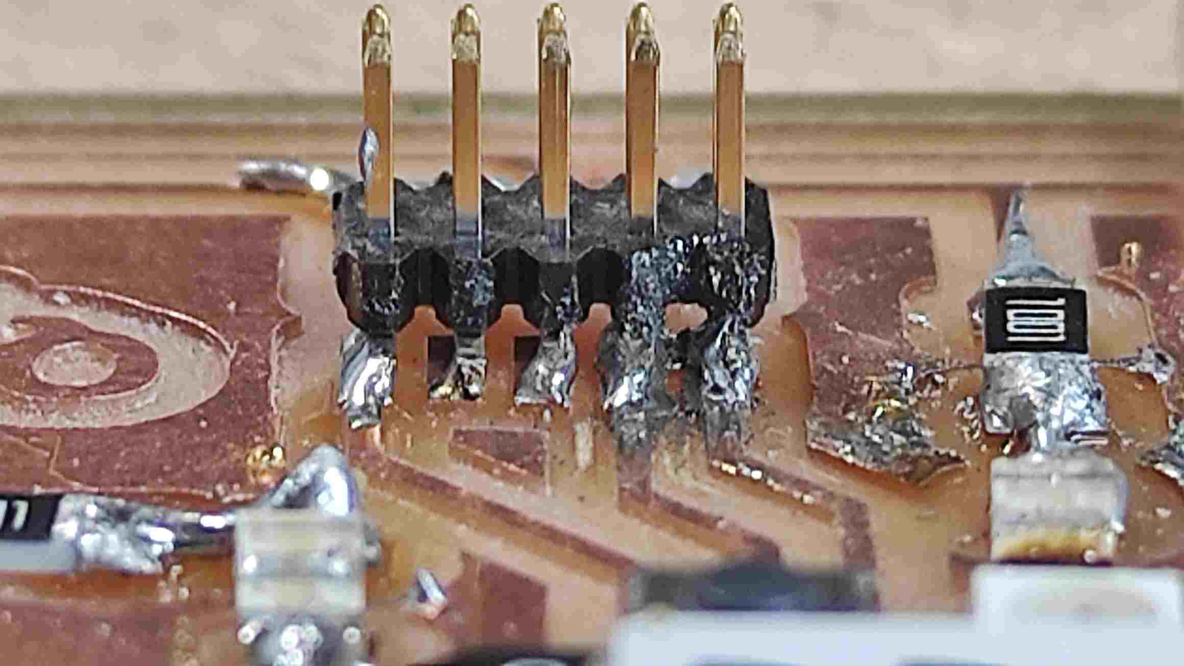
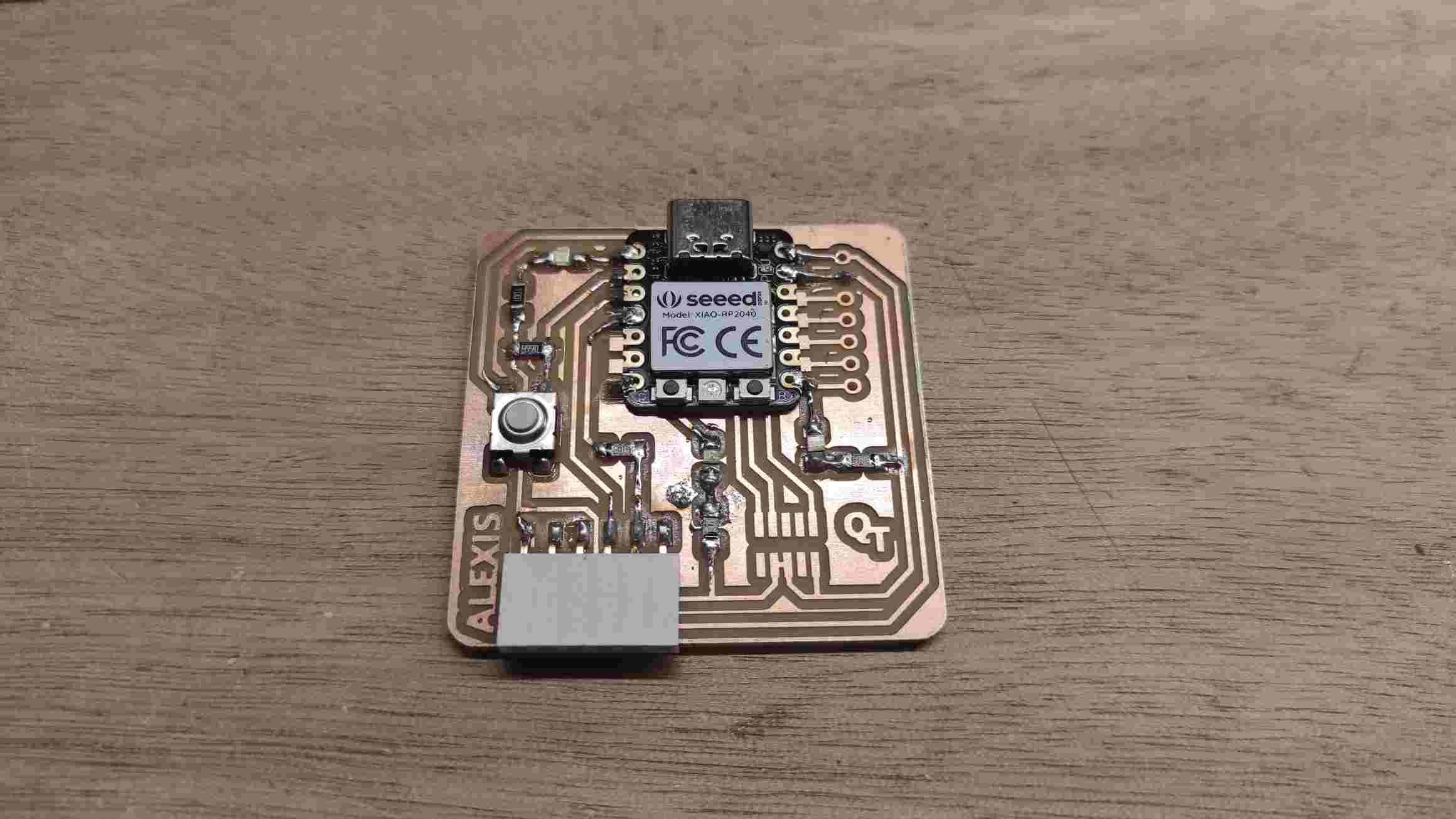
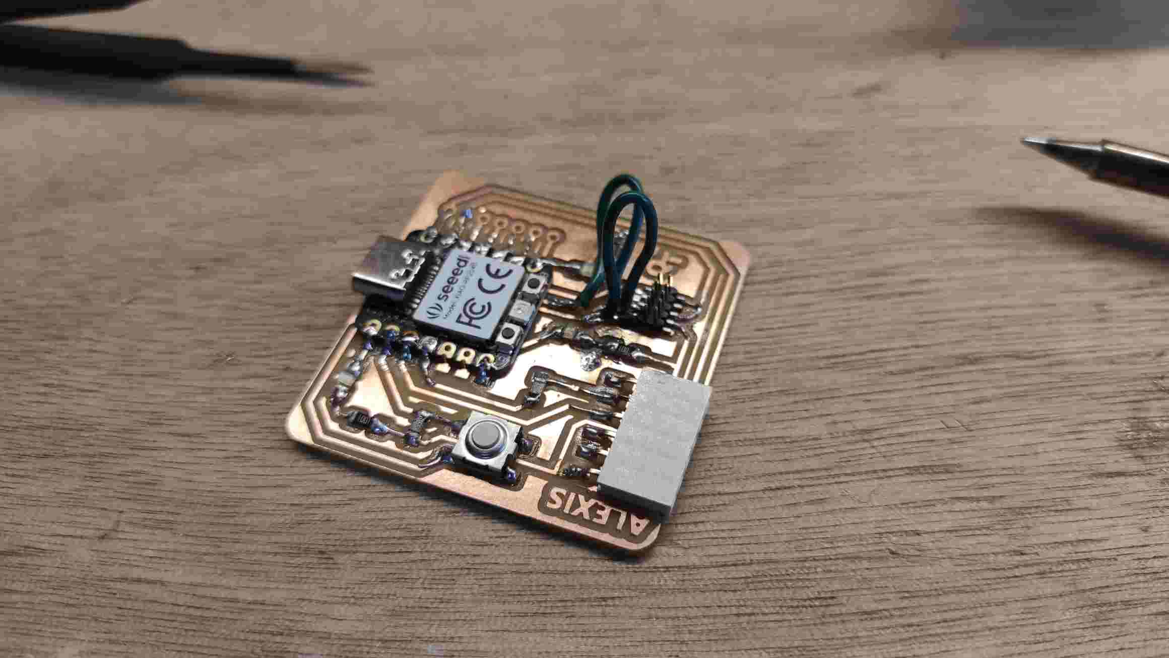
To repair it, I used wire. It wasn’t simple. Some copper get torned off again. I tested the continuity with a multimeter and it finally seemed connected as expected.
Testing
To test the PCB, I followed the indication of the Git Documentation.
I first had to download Arduino IDE.
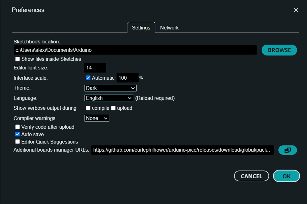
As described, I added the recommended additional board manager URL in the preferences.
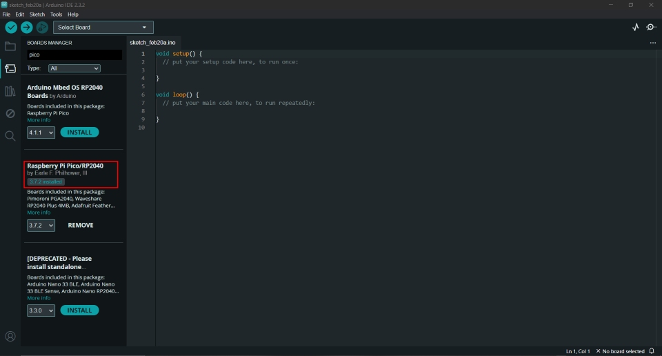
Through the Boardmanager tool, I searched for pico and downloaded it.
Then I add the board as the current board and set the port (the board needs to be connected).

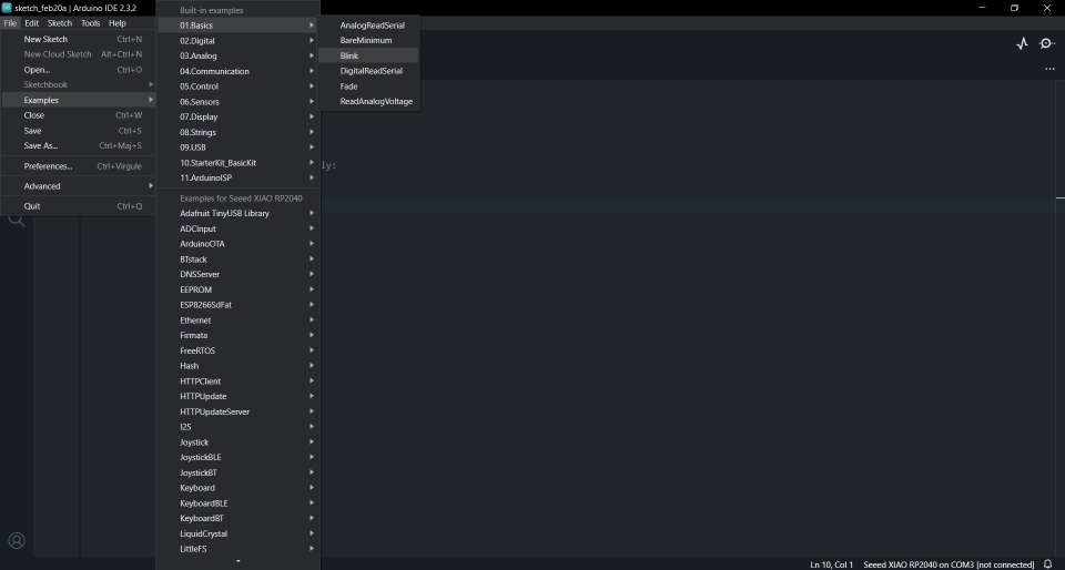
The next step is to load the Blink program. I searched on the Quentorrens documentation and din’t find it. I randomly searched on other students pages and find the response on Damzang Chimi Seldon page.
The Blink program is one of the Basic examples that can be found in the Arduino IDE
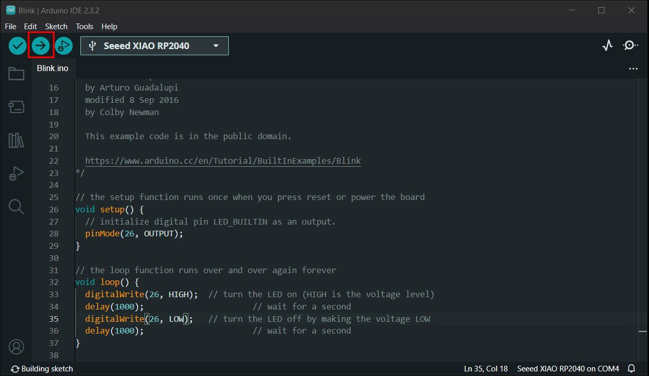
Clicking on it open a new window with the program to upload but first you need to change the “LED_BUILTIN” parameters to the GPIO number of the pin (26 for our example). Finally, you can click the upload button.

The IDE might take a little time compiling the program.

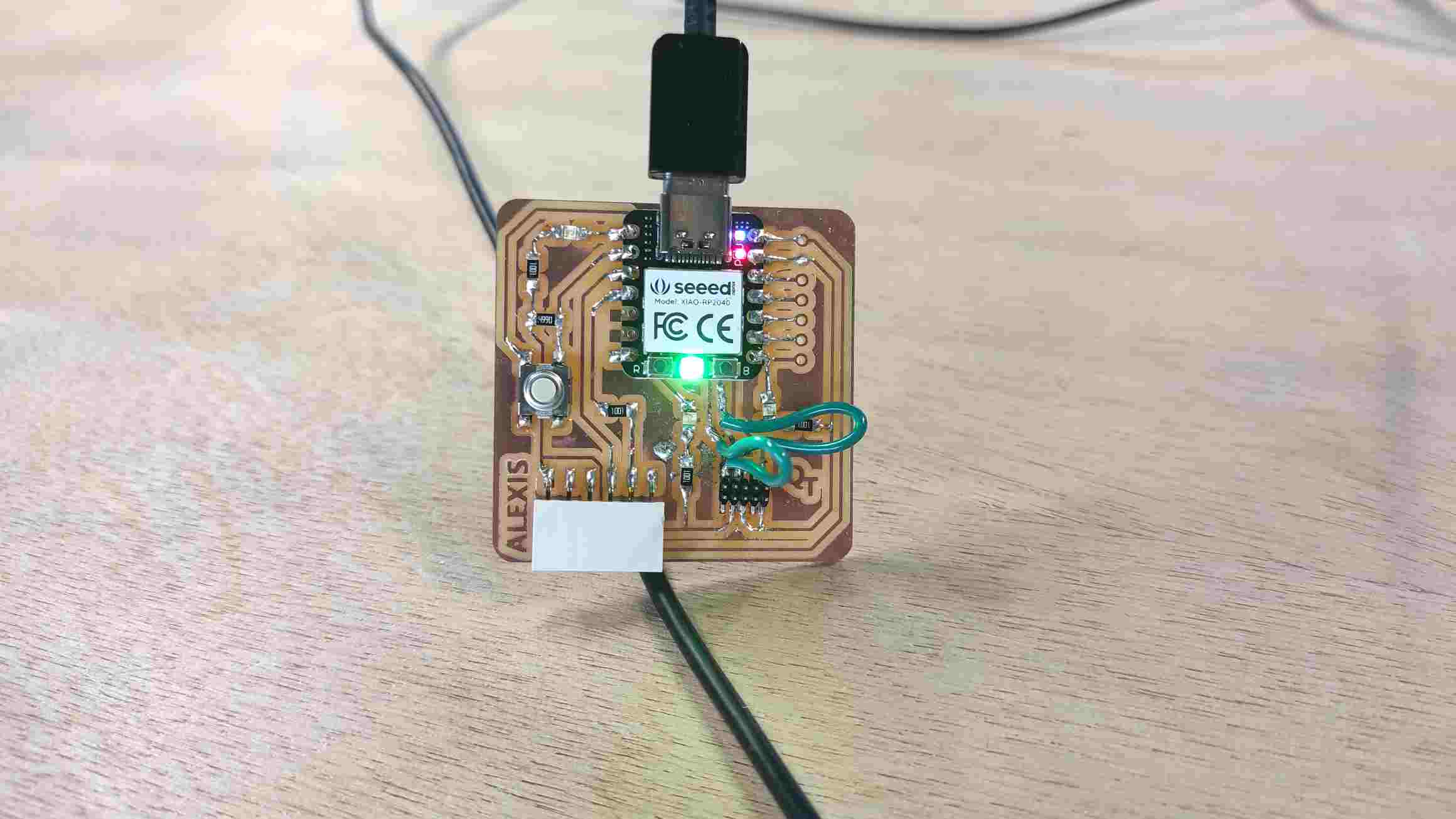
The LED on the left side should now blink.
You can also change the pin on to 0 or 1 in the program to test the other LEDs.
To finish, I asked chatGPT for a program to alternate the LED enlightment. I came up with a program I slightly change (pin and delay).
Class Archive
Here are the files created for this week assignment :
- linetest traces RML file
- linetest interior RML file
- personnalized quentorres traces RML file
- quentorres drills RML file
- quentorres interior RML file
- personnalized quentorres traces PNG file
- alternate blink program
Impressions of the week  
During this week, I gladly learned to use the end mill machine and make me wait for PCB design and more conventionnal software to export them. The soldering wasn’t an easy step but managing to repair my mistakes made me a little bit more confident for the next ones. Although, seeing the program working as needed was quite comforting.
