7. Computer-controlled machining
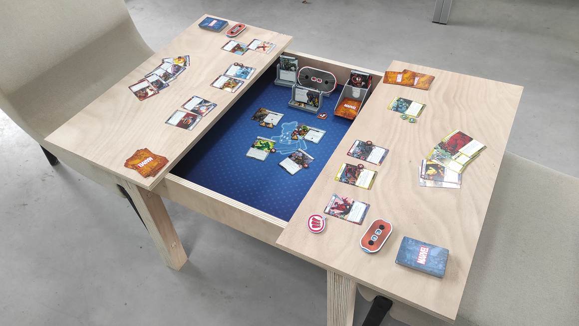
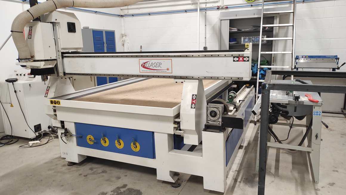
Hero Shot
Assignment :
Group assignment:
- do your lab’s safety training
- test runout, alignment, fixturing, speeds, feeds, materials and toolpaths for your machine
Individual assignment:
- make (design+mill+assemble) something big (~meter-scale)
- extra credit: don’t use fasteners or glue
- extra credit: include curved surfaces
Group Assignment
You can find our group page here and this week group assignement here
Safety Training
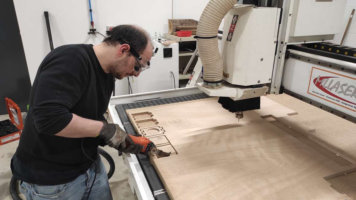
During our CNC workshop, we had a session on safety and risk prevention.
Before starting any work, we need to check :
- the machine : good mechanical state of the cutter, no obstacles to the machine mobility on and around the machine, clean bed.
- the material : compatible to the machine, good fixturing.
- the file : parameters (speed/feed) set for the type of material and adapted to the machine limitation, cutting depth.
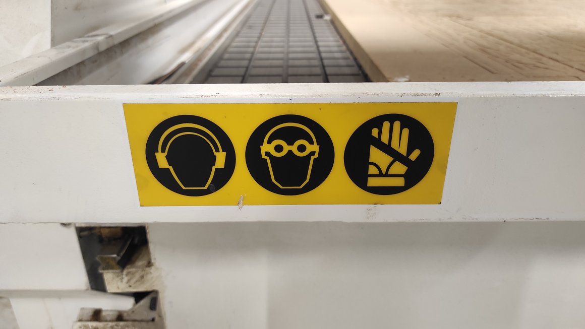
- the human factor : good physical and mental condition, with the company of ta capable co-worker, wearing appropriate clothing, wearing protections (ears, face and hands).
During the work :
- the machine : check regularly the tool path, and the cutting depth, spindle, aspiration.
- the material : check for debris to avoid breaking
- the human : stay away from the mill, pause work before checking, be aware of abnormal sound or smell, keep wearing
After work :
- the machine : clean the table of dust and debris, check axis for debris, check dust containers.
- the material : dispose remaining material if needed, check the quality of the sacrificial layer
- the human : store protection at the right place
Fixturing
Agrilab’s machine possesses a vaccum table but for smaller project the number of vacuum holes doesn’t permit a great fixturing. So, the vaccuum table is used to fixture a sacrificial layer that permits using screw to fix material. The vacuum table has also efficiency through the sacrificial layer and can reduce an unexpected curves on the material. The sacrificial layer also permit to protect the bed from overcutting.
Speeds/Feeds
For my personnal assignement, I tested a joint and used it to test a different speed and feed for group assignments
Using the Millcutter Datasheet, I entered the cutting parameters. Sorotec propose 500 m/min cutting speed and 0.060 mm/tooth/revolution to cut soft wood with a 6mm flat mill. It correspond to 26000+ rpm spindle speed but our machines is limited to 24000 rpm. As it is, I fixed the speed through spindle speed at 24000 rpm and surface speed is set from it at around 450 m/min. As recommended during the workshop, I copied the plunge feedrate for the ramp feed rate and set the stepdown at the diameter of the cutter and the stepover at 0.45 of the cutter diameter.


I made another try with CNCFraise Recommandations (in French). It propose 250 m/min cutting speed and 0.024 mm/tooth/revolution to cut soft wood with a 6mm flat mill.

Obviously, the Sorotec configuration is going very faster, the machine is louder but it doesn’t seem to have an impact on the quality of the production. Probably, the milling cutter will wear out faster. The finish cuts are as rough on the two products.
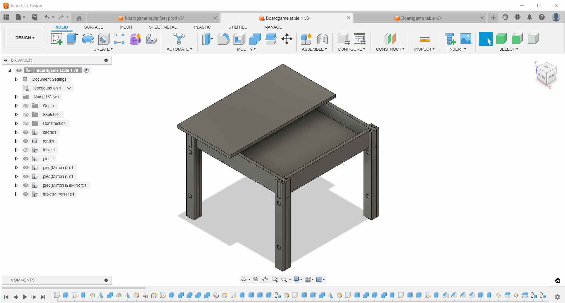
Individual Assignement
After Neil’s Lecture, we had a Workshop animated by Nicolas about Design and Manufacture in Fusion 360 and a second Workshop about the machine itself.
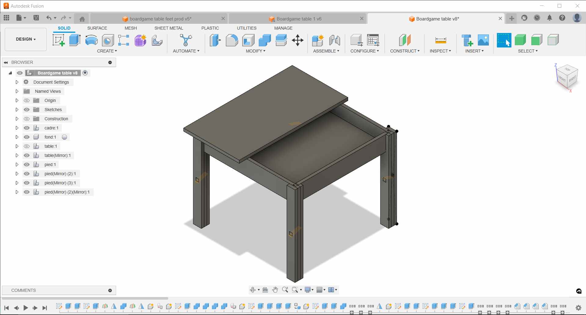
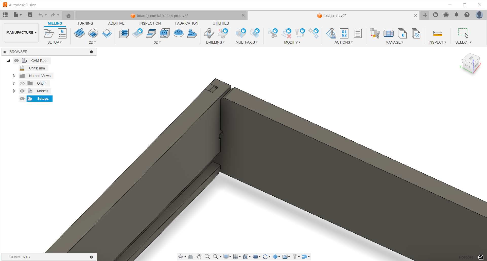
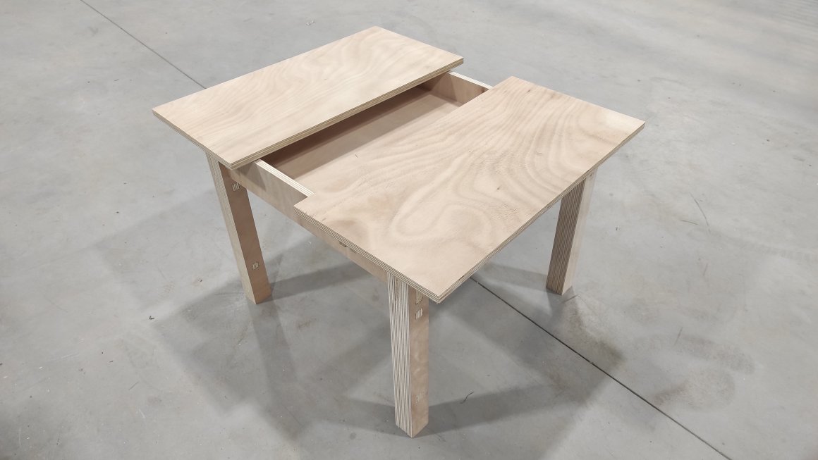
I designed on Fusion 360 a boardgame coffee table. I designed it to be without screws or nails. It was quite tricky to do. I used an extension to add Dog-bones and T-bones as recommended during our Workshop animated by Nicolas about Manufacture in Fusion 360.
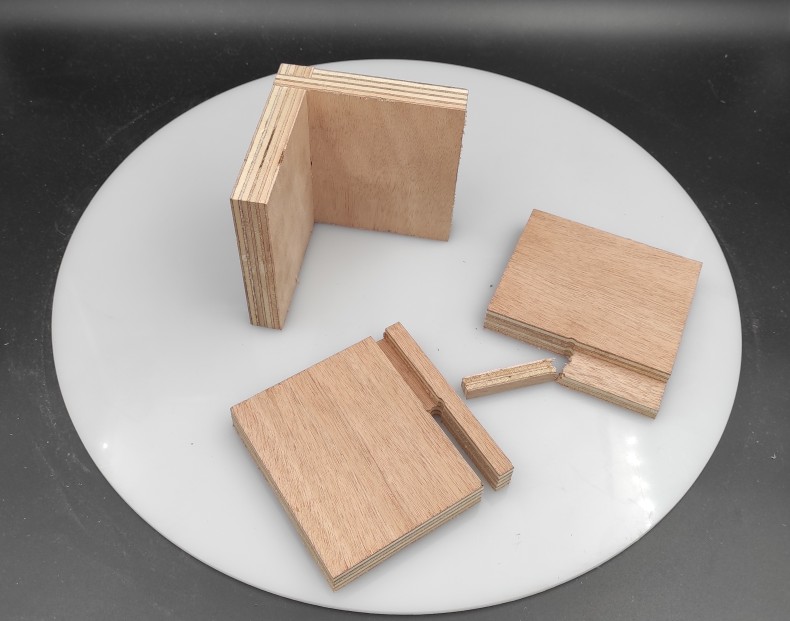
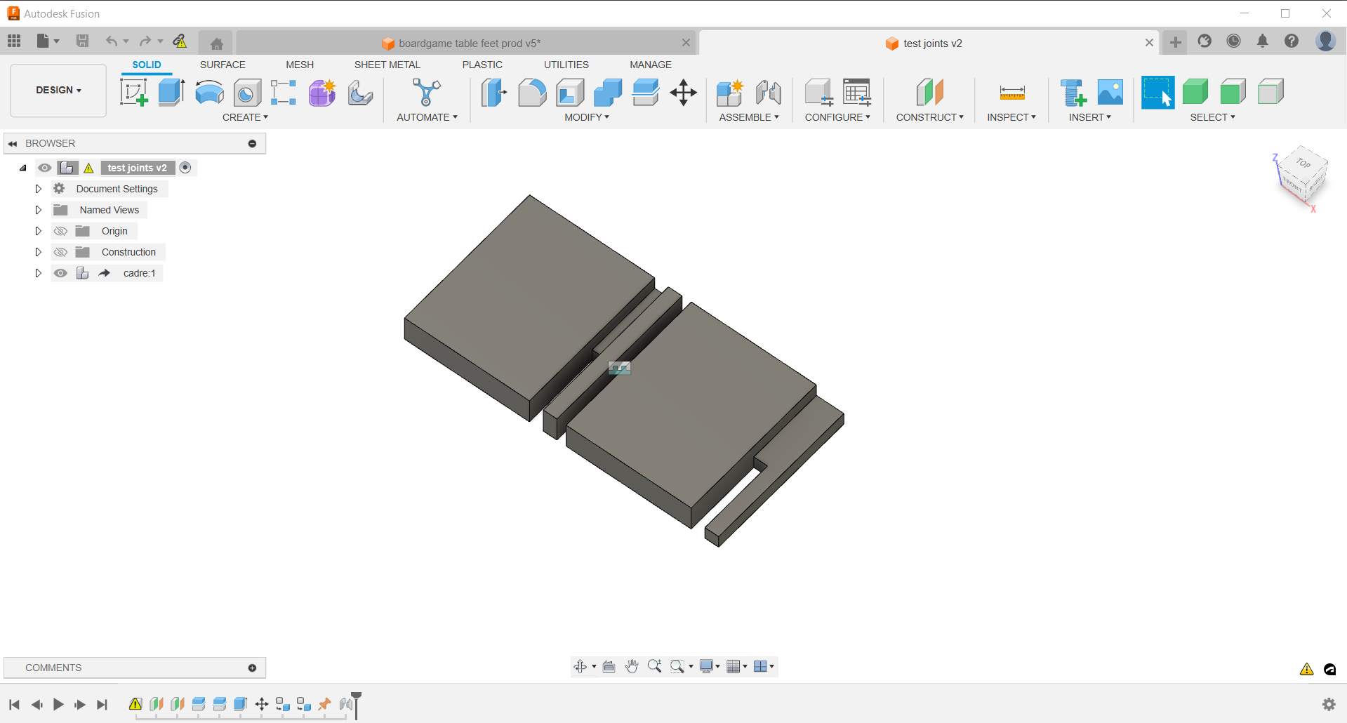
Before finishing my model, I tested a joint I modelized for it. I used the derive options to export the frame of my table and cut just a corner of the new file with the Deign module. I used the joint option to align the 2 parts.
Creating tools in Fusion 360 Library
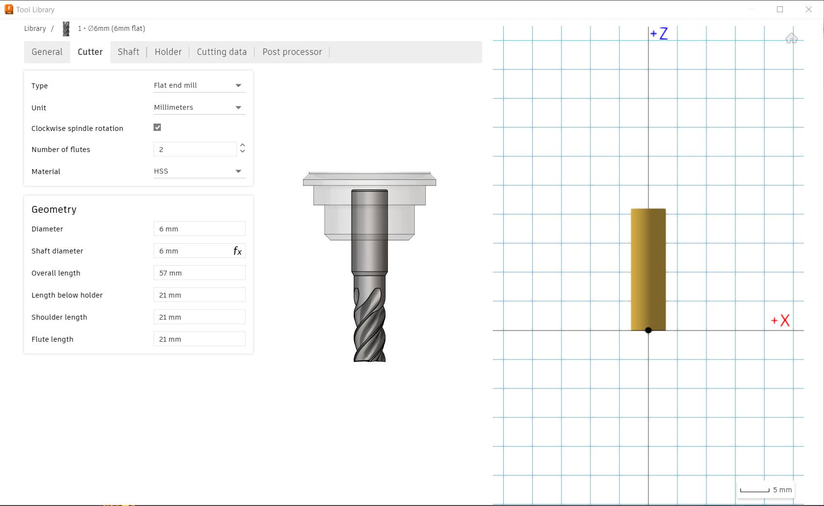
Before generating cutting in Manufacture module , I needed to add the millcutter in the Tool Library and the preset for the material I will use (plywood)
We first used a 6mm Flat Endmill :

Adding Millcutter, I entered the cutter geometry based on the Sorotec cutter page in the Fusion tab.

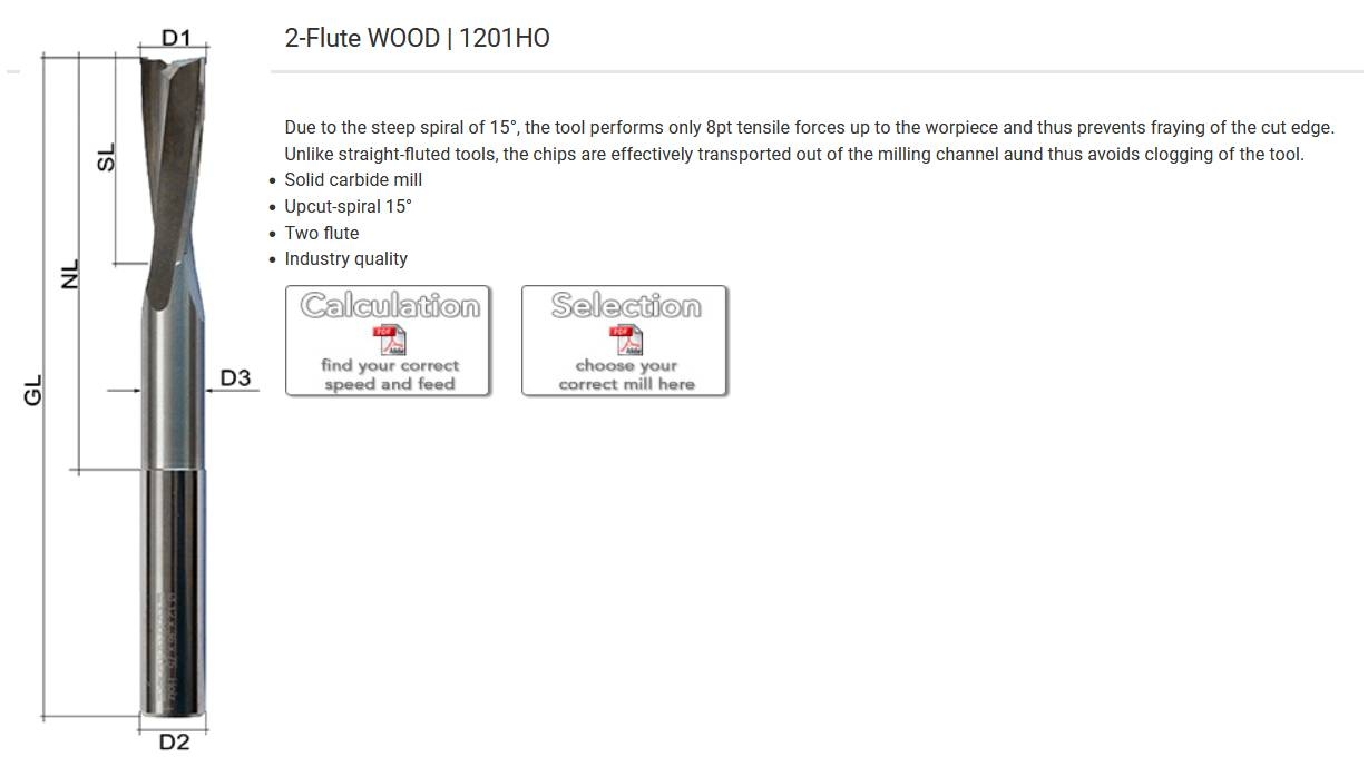
Using the Millcutter Datasheet, I entered the cutting parameters. Sorotec propose 500 m/min cutting speed and 0.060 mm/tooth/revolution to cut soft wood with a 6mm flat mill. It correspond to 26000+ rpm spindle speed but our machines is limited to 24000 rpm. As it is, I fixed the speed through spindle speed at 24000 rpm and surface speed is set from it at around 450 m/min. As recommended during the workshop, I copied the plunge feedrate for the ramp feed rate and set the stepdown at the diameter of the cutter and the stepover at 0.45 of the cutter diameter.
I profited of this test to make another try with CNCFraise Recommandations (in French) to fulfill our group assignement. It propose 250 m/min cutting speed and 0.024 mm/tooth/revolution to cut soft wood with a 6mm flat mill.
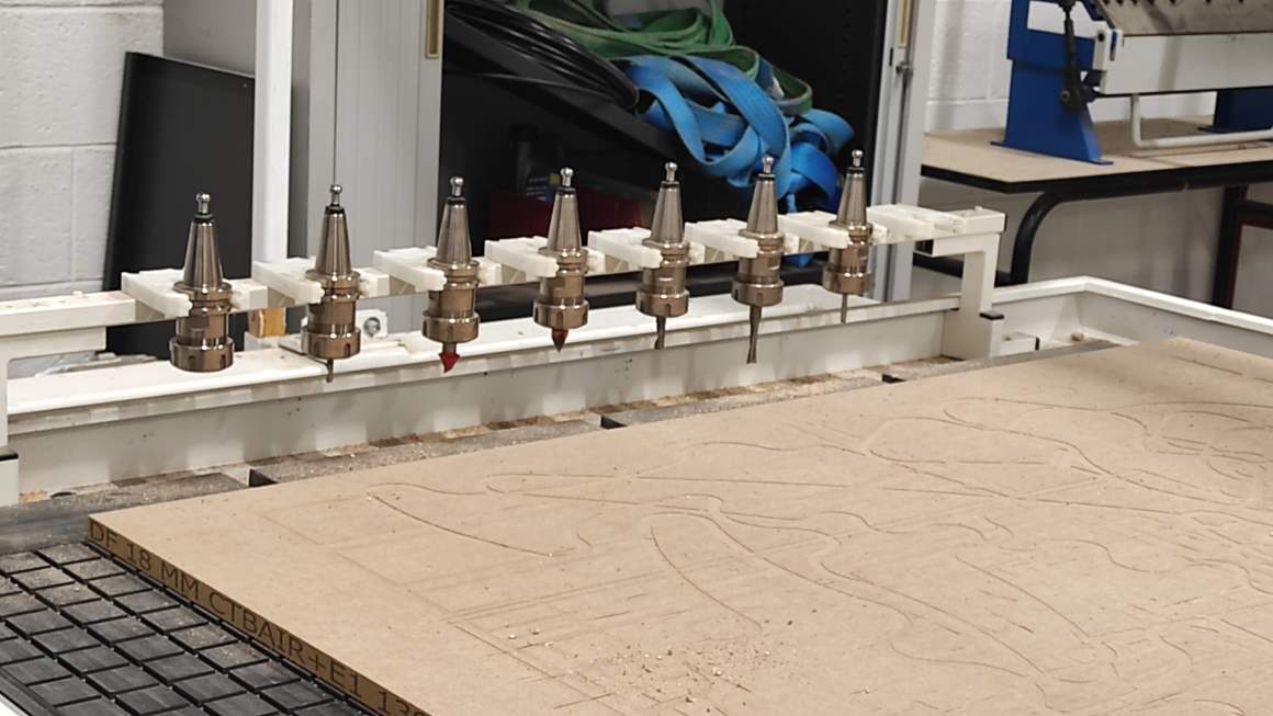
Finally, the machine using a multi tool rack, we have to set the right position in the post-process tab (7 for 6mm Flat Endmill)
Manufacture - New Setup
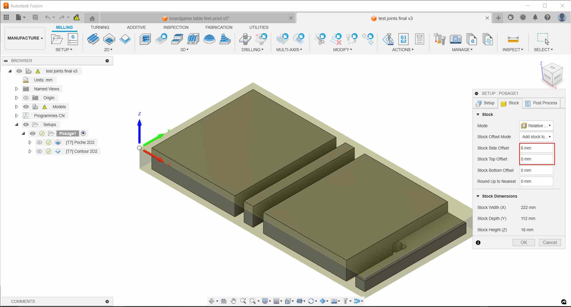
To create a file for the milling, you first had to create a posage by clicking on the “new setup” icon in the Setup menu.
the yellow triangle means the model this one derived from has changed, so this one could be updated

It will create automatically a stock fitting your model. A new windoms open with parameters to enter. Milling is already set as operation type. But most important, we have to set the origin and the axis to fit the machine ones. Preferably chose a point at the top of the stock box, cause you’ll probably set your machine Z offset at the top of your material.

You also have to select the part of the model concerned by the milling.

Then we define our stock on the next tab. A 1mm offset has been automaticaly generated on the side and the top of the model. You should change the top offset at 0 to fit your materials. I also changed the side offset to correspond the milling cutter as a security marging.
We don’t set the post process yet. We will do it when generating the Gcode.
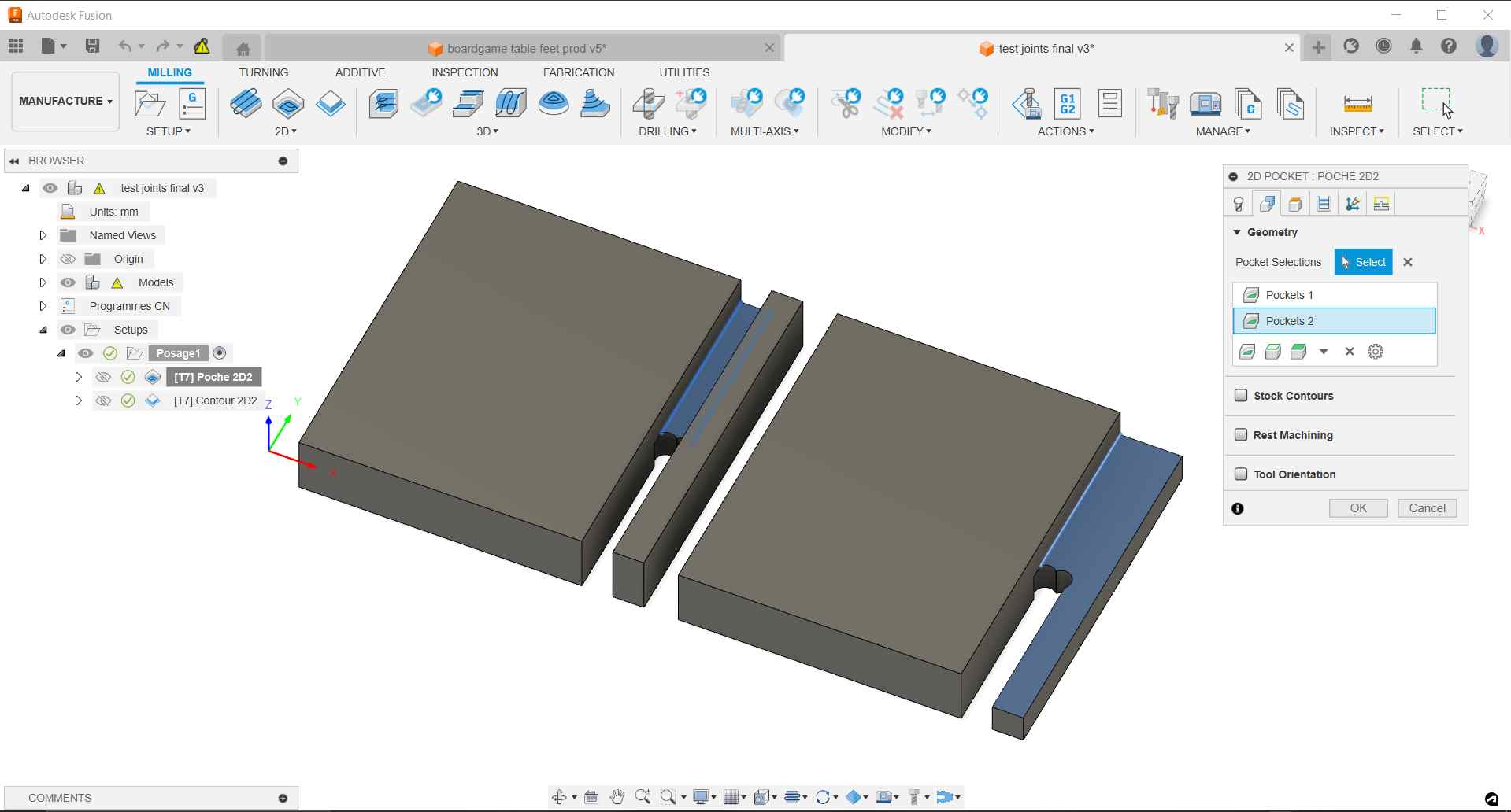
2D Pocket
Starting with the milling, first comes the 2D Pocket under the 2D menu. 2D Pockets are used to mill flat surfaces allowing stepover for better results. When creating a new pocket, you had to choose a tool in your library and the preset corresponding your work. I selected one I created sooner. The other parameters change automaticaly for the one corresponding to the tool preset.

In the second tab, Geometry, you select surface you want to mill.
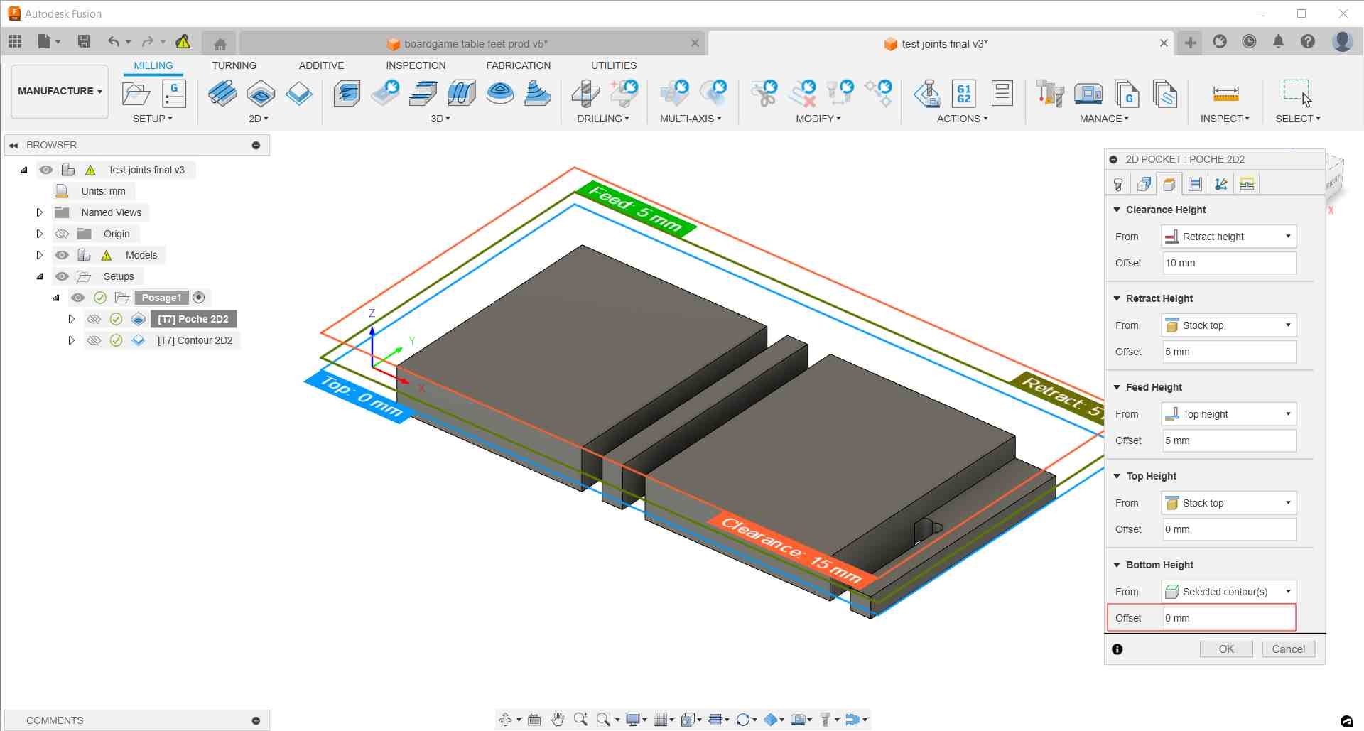
In the third tab, you can define different heights to secure the movement of the milling cutter and for the cutting. For the pocket, it’s quite importantthat the bottom height is set to 0 to avoid cutting to much materials.
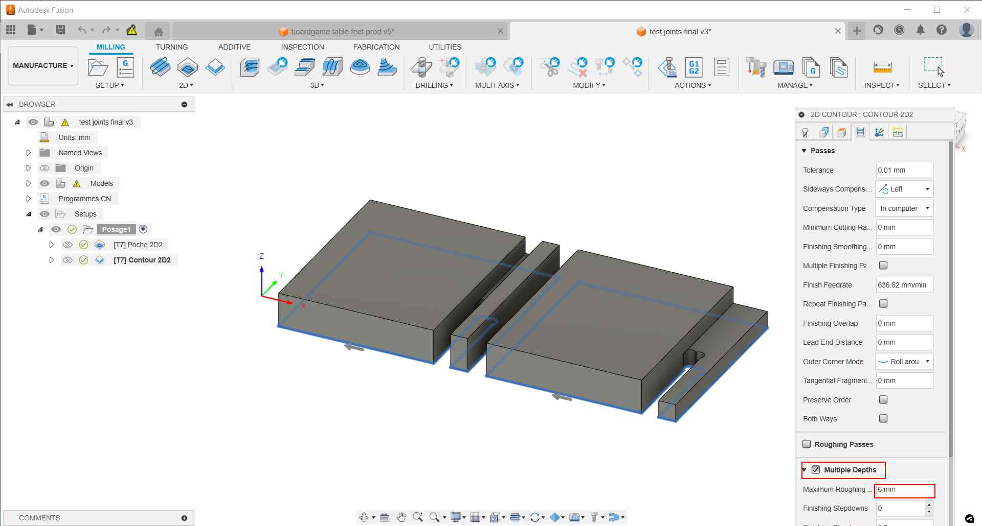
On the fourth tab, Passes, we have a reminder of the stepover define by the tool parameters. It’s important to activate Multiple Depth and verified the maximum cutting depth don’t exceed the tool diameter.

For our machine, fifth tab, Multi-axis, don’t need to be change.
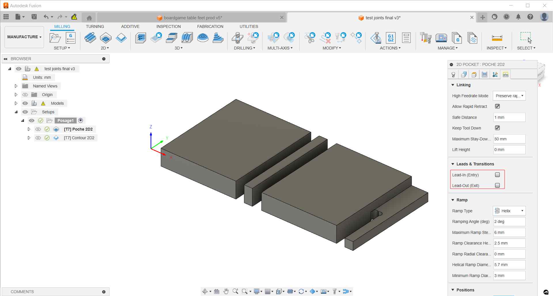
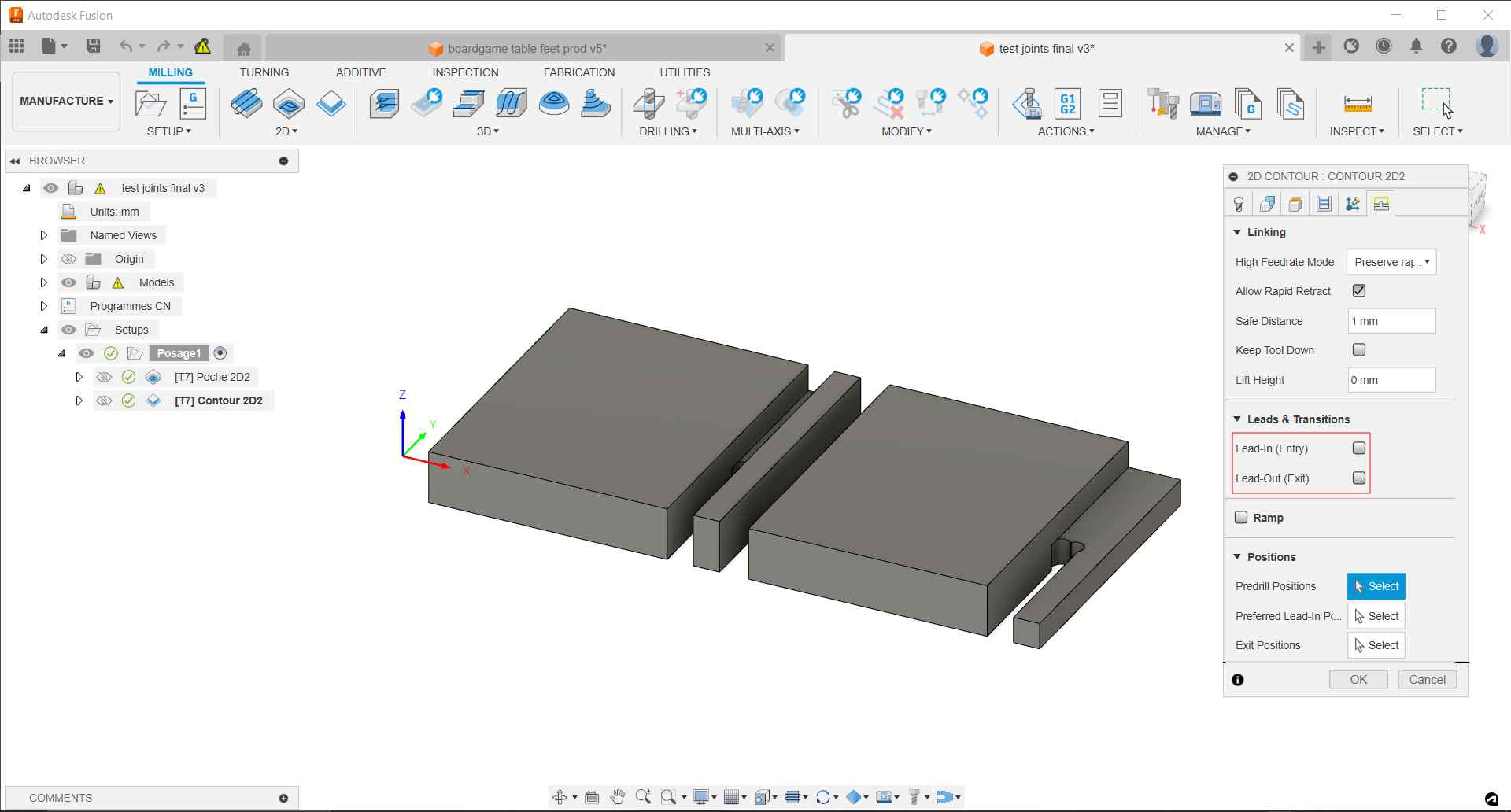
And finally in the sixth tab, linking, you can de-activate lead-in and lead-out. The Ramp type can be interesting to change in some circumstances. For example, if you’re pocket is to thin to allowed helix approach you can opt for a zig-zag one.
You can click OK to validate the pockets. The software will create the tool path for it.
2D Cutting
2D cutting to create a piece from the stock. The functions is available under the 2D menu.
As for the pocket, you have to choose the tool and the preset.

In the Geometry tab, you have to select faces, edges or silhouettes you want to cut around. You need to add tabs to maintain the pieces on the stock until the end of the milling. If you don’t, parts may come loose and be damaged, potentially being expelled from the machine, the cutter may break, and debris could injure individuals near the machine. A 1.5 or 2 mm thick tabs should be enough to maintain the different parts. They can be distributed automatically or manually.

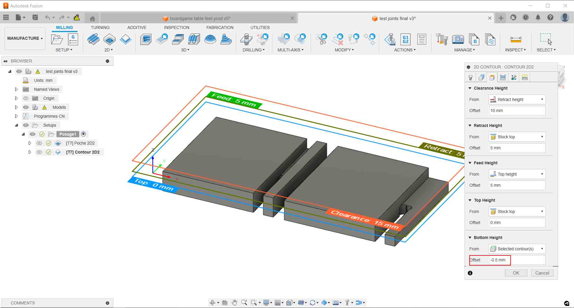
In the Height tab, we set an offset of -0.5 or -1 mm to be sure the stock will be completely cut even if it’s slightly curved.
As for the pocket, we activate the Multiple Depths options in the Passes tab and verified that the maximum cutting depth don’t exceed the tool diameter.
And finally, we also de-activate the lead-in lead-out entry in the Linking tab.
Simulation
Now we have a representation of the toolpath for the milling of the pocket and the cutting.
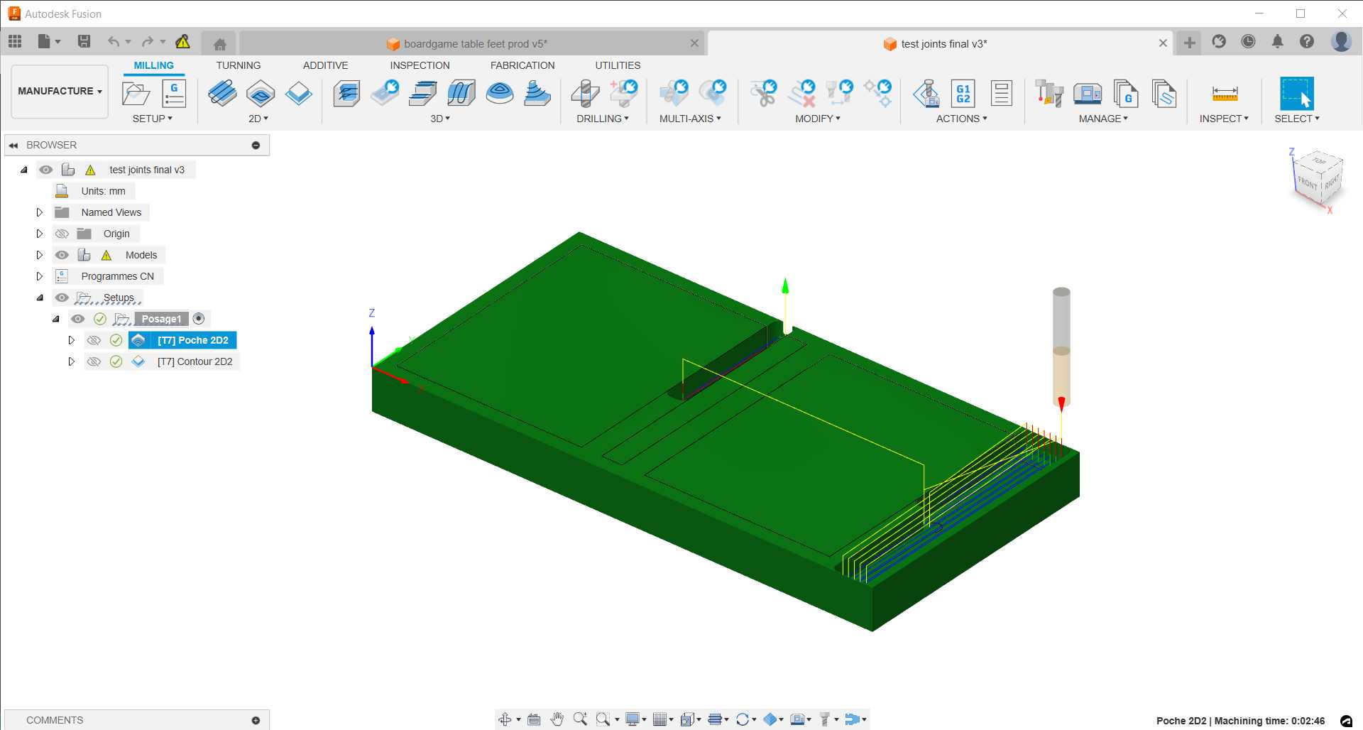
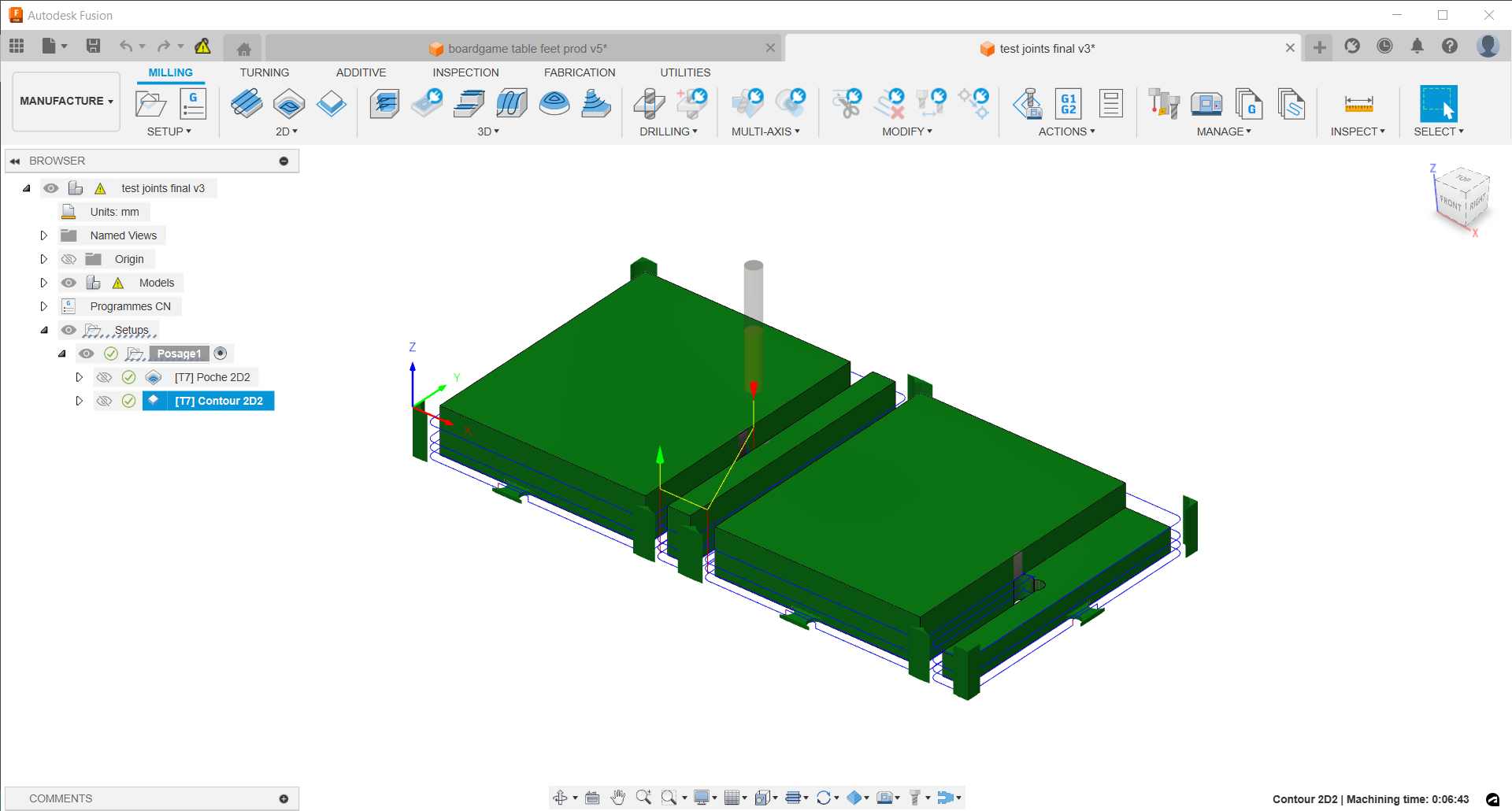
Under the Actions menu, we can chose the simultate options to have a visualisation of the tool path.

Generating Gcode
Under the Actions menu, we need to click the Generate options

It opens a new window where we need to chose a post process, Mach3Mill for Agrilab machine. Then we can name our file and chose an output folder. Before clicking “Post” we want to check “open NC file in editor” cause we’ll need to modify a line in the code.

The file will open automatically and we have to erase the line beginning by G43 corresponding to a tool parameter that is not set in the machine.

The file can now be saved on the machine’s USB key.
Machine Setup
The Machine is a GrandRouteur CNC, a repackaging of a chinese machine.
Basic reminder of safety measures is stick to the machine.
It uses a multiple tools rack for automtic changes.
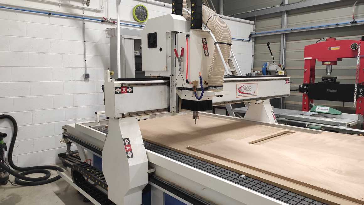
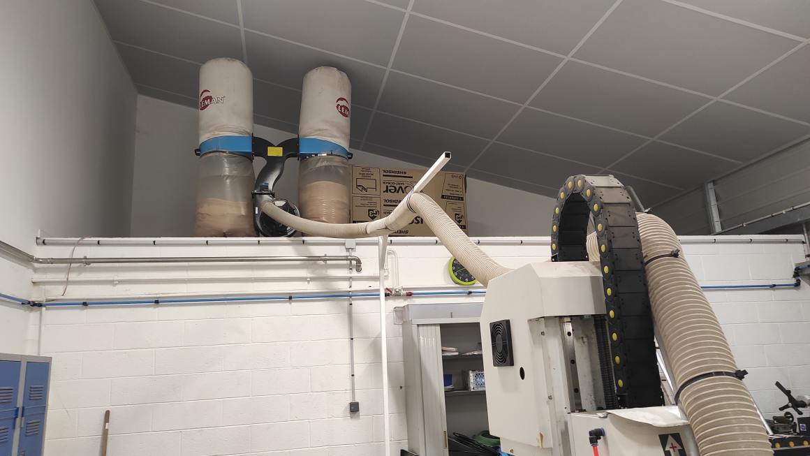
The 3 axis movement are applied on the head. The machine is equipped with a vaccum table and a sacrifical layer.
Aspiration around the cutter leads to a dust collector.
The control unit and the remote control are used to pilot the machine.
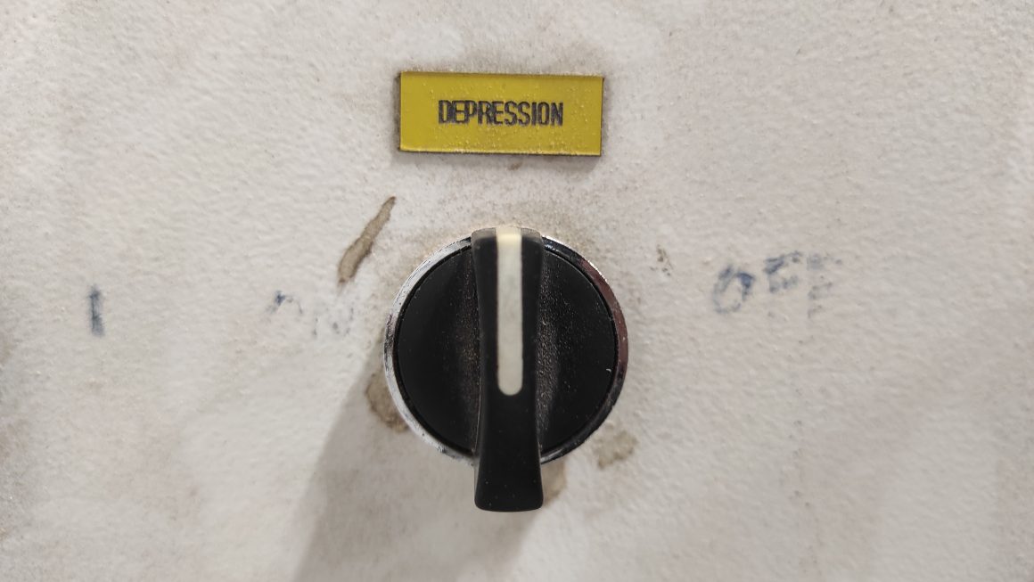
The control unit has 3 switches, from left to right : to lower or raise the brush, to activate the aspiration and to activate the vacuum table.
The three button are Off, On and Emergency Stop.


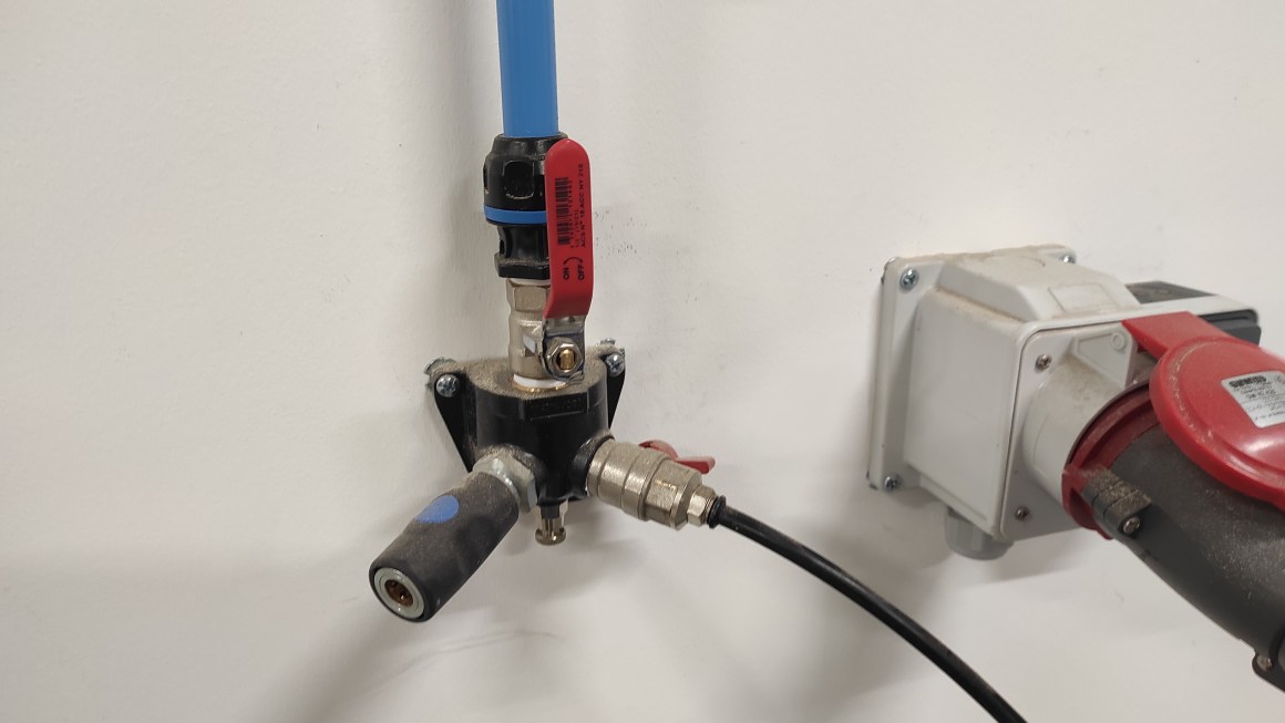
The machine also use air pressure to maintain the collet and the air lever needs to be open befor turning on the machine.
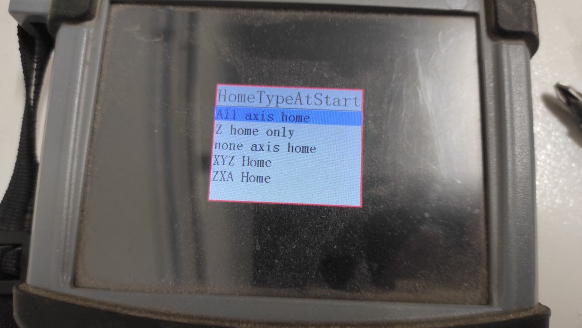
After starting the machine, the remote control ask confirmation to set Home Axis.
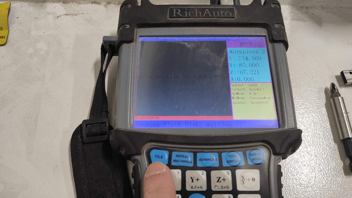
The remote control use USB-key to import files. You get access to it by the “File” button.

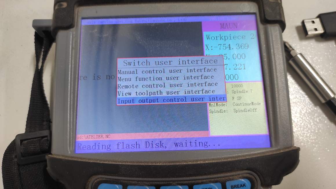
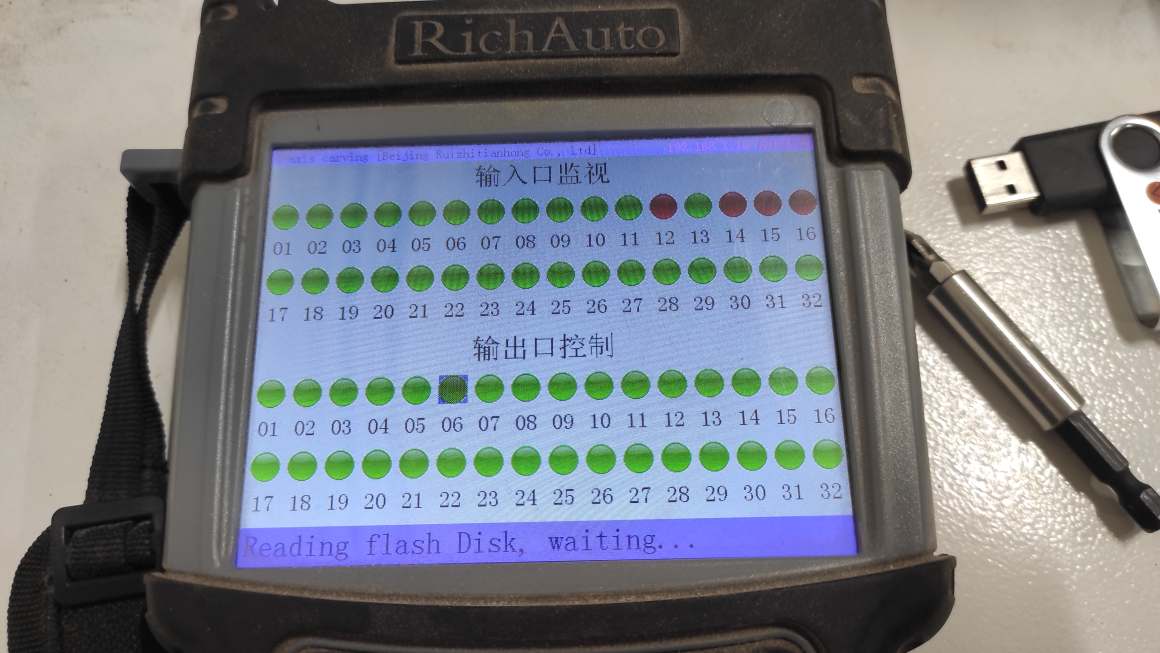
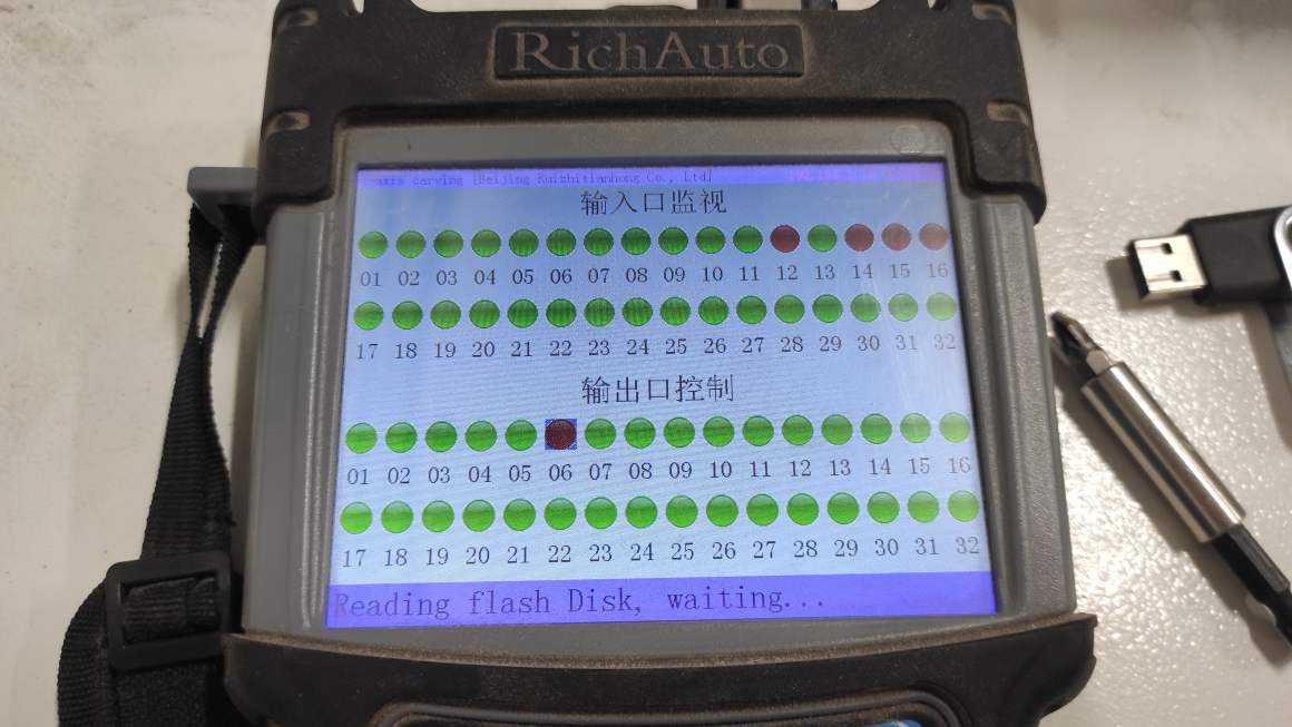
The brush control need to be re-activated at each starting. Go to Menu > Input output control > select output 6 > push run button (output turn red) > push menu > Manual control user interface. The process is not very intuitive, sometimes you have to push “ok” and other time “run”, “red” means “activated” and “green” “de-activated”.

You can manually set the XY origin by positionning the milling cutter at the right position using the remote control then push the “XY>0” button.

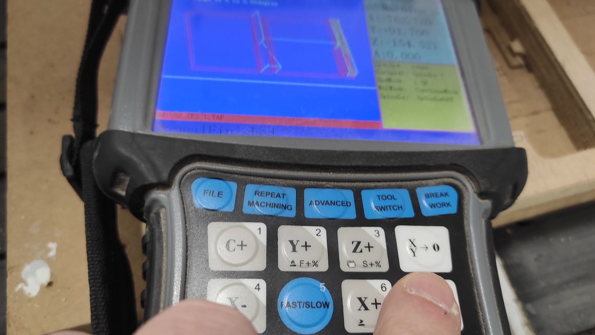
To set the Z origin, we used a probe height and a clench and pushed the “toolset” button on the remote control. We set it first in the air to verify the conductivity then we made it on top of the material…

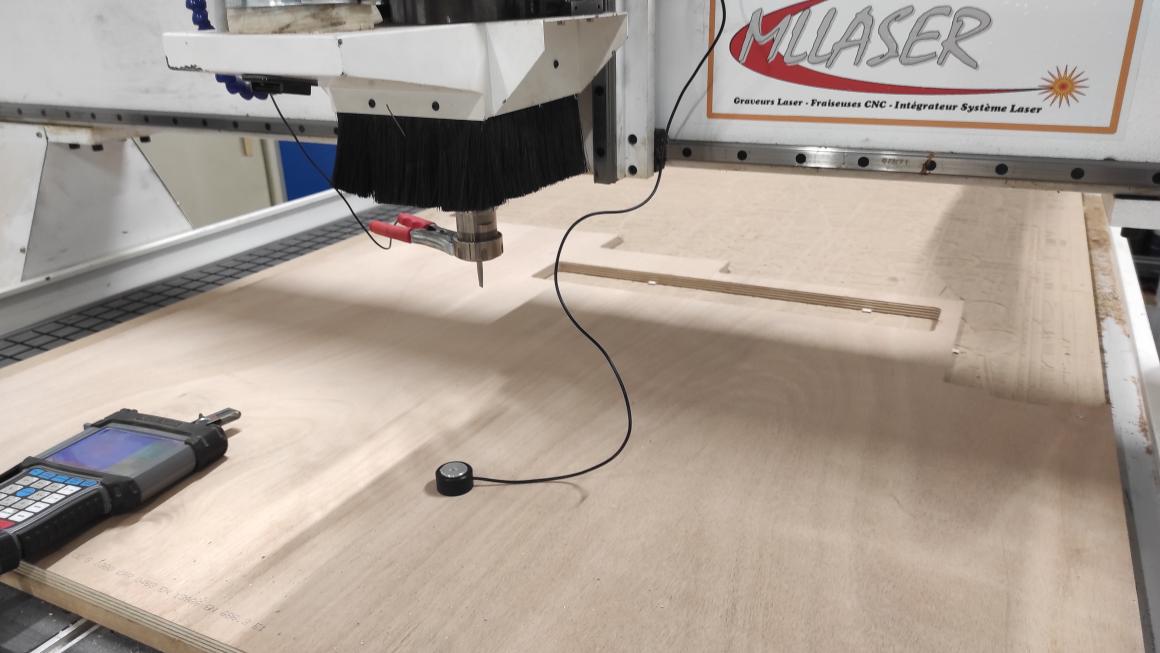
… without forgetting to turn on the vaccum table (as a mental health caregiver, I love this switch).
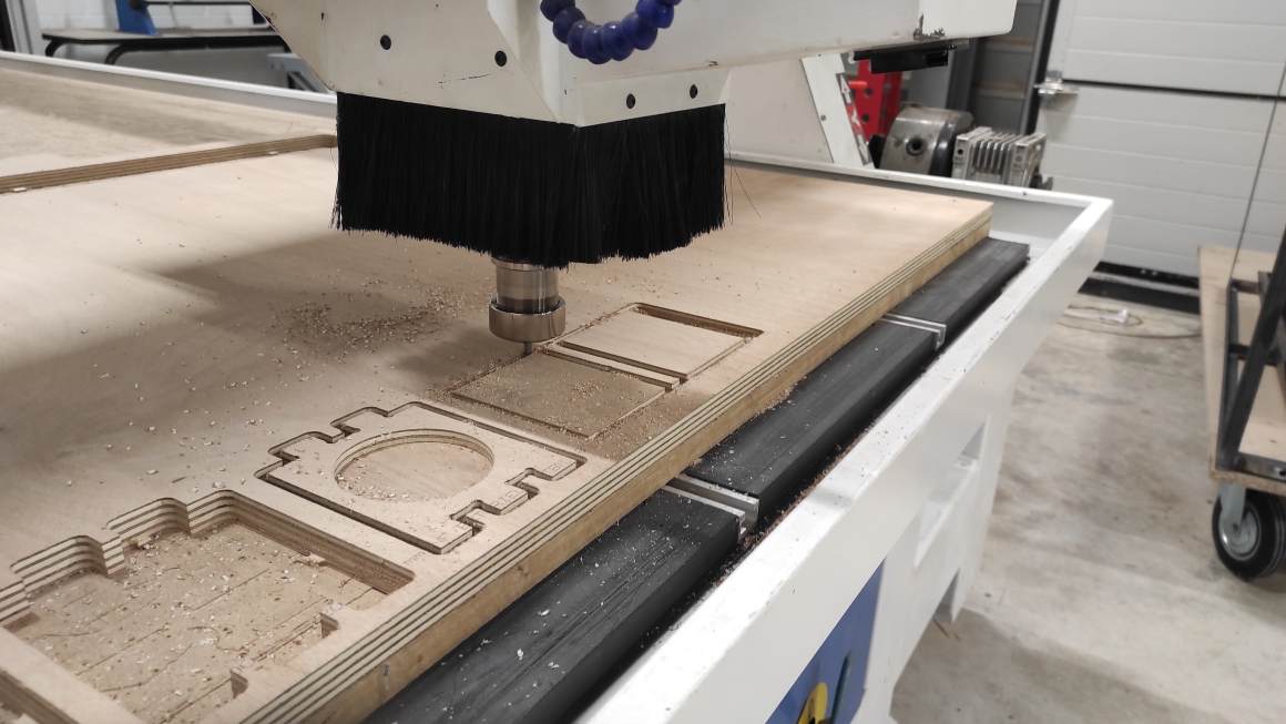
Milling
Once, the file is ready, the origins are set and the brush is enabled, we can turn on the aspiration and the vacuum table and start the milling by pressing “Run” on the remote.
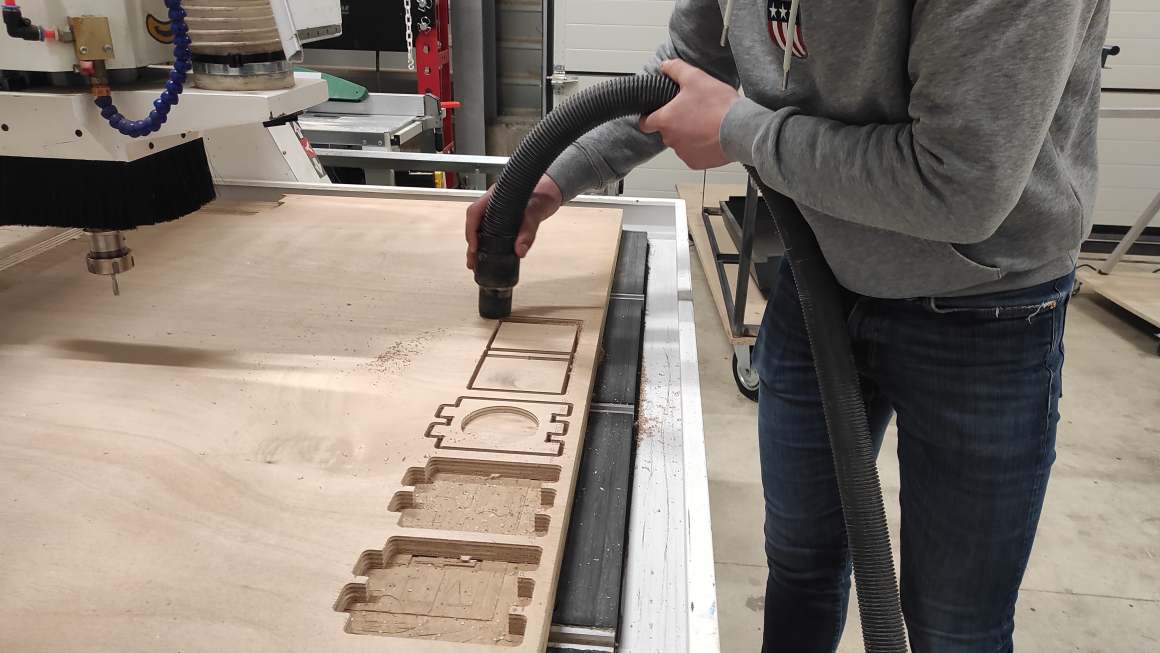
Once the milling is done, we vacuum the chips and cut the tabs with an oscillating tool blade.
The results was quite good for both, but I should have added chamfers. There is not a real difference between the two configurations. At 500 m/min, the machine is louder but it doesn’t seem to have an impact on the quality of the production. Probably, the milling cutter will wear out faster.
Final design
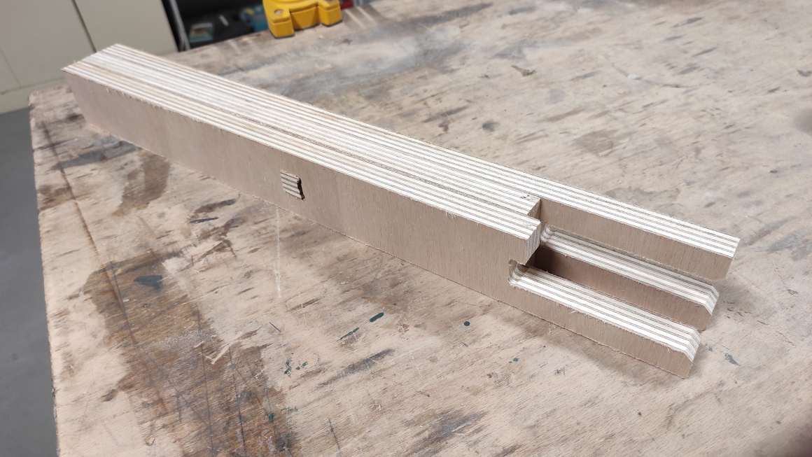
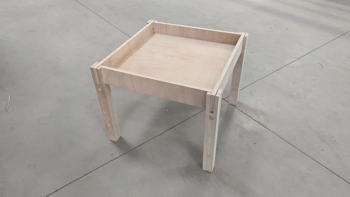
For the table, I finally change the joints cause it was quite fragile (again I broke one of them before taking photos) plus it needed to have pokets on each sides of components. I thought that was too complicated to learn and do in the time I disposed for the assignement.
The new design use chamfer press-fit joints, with the leg going around them.
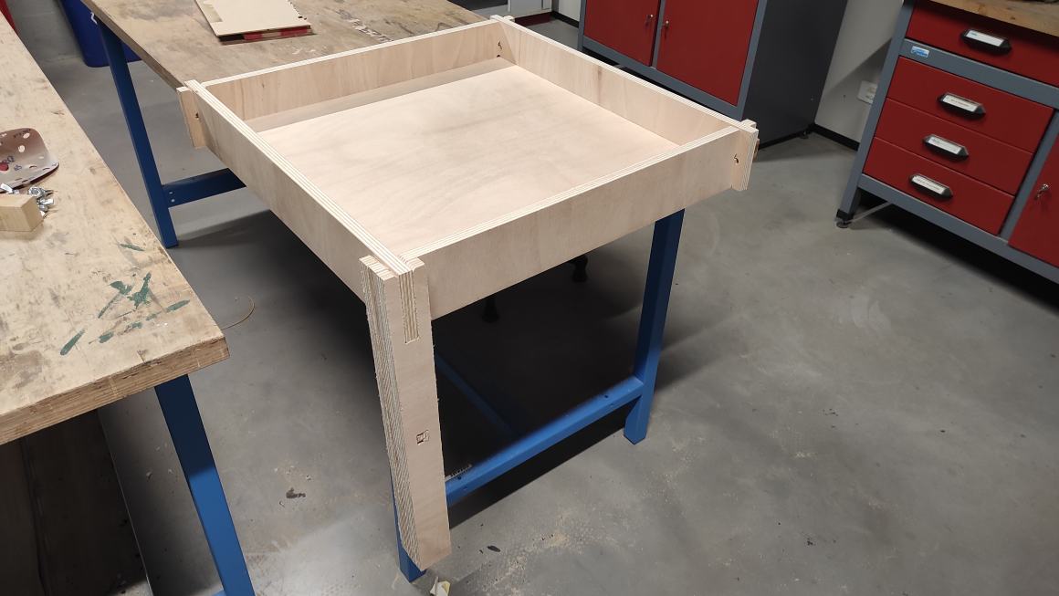
I prepared seperated files for the frame, the legs and the tabletop.
Queuing with my co-students for the milling, I only had time to make a foot and the frame.
The Assembly was difficult due to lack of clearance. The leg on the other part was a bit too loose. I updated the file to make a second insert.
Also, I change the milling cutter for a 10mm one after making the foot, to make the other parts faster. The counterparts is having bigger and more visible Dog-bones.

Errors and Mistakes
During the different processing, I made multiple errors and mistakes.
The biggest one was forgetting to put the clench for conductivity probe on the mill to set the Z origins and avoid to set a first Z origin in the air. The cutter went trough the probe making an hole in it. Hopefully, I stopped it before it goes too far and the endmill didn’t broke. Looking at the probe I wasn’t the first person to do it. From this time, I always test the probe in air.

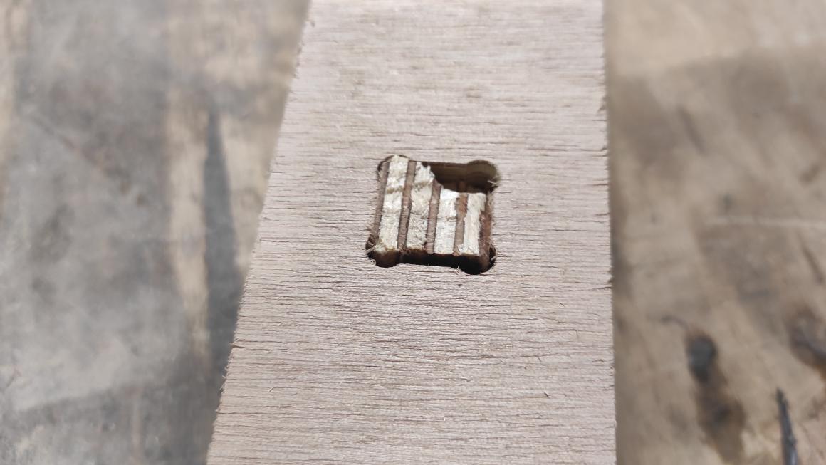
Another big mistake occurs when milling the tenons for my table leg. The tabs were not numerous enough or thick enough (1.5mm) and broke. The tenons came loose and were damaged by the cutter. There was no projection thanks to the brush around the cutter. From there I added extra tabs and made the 2mm thick. Somehow the tenons still fit in the mortise.
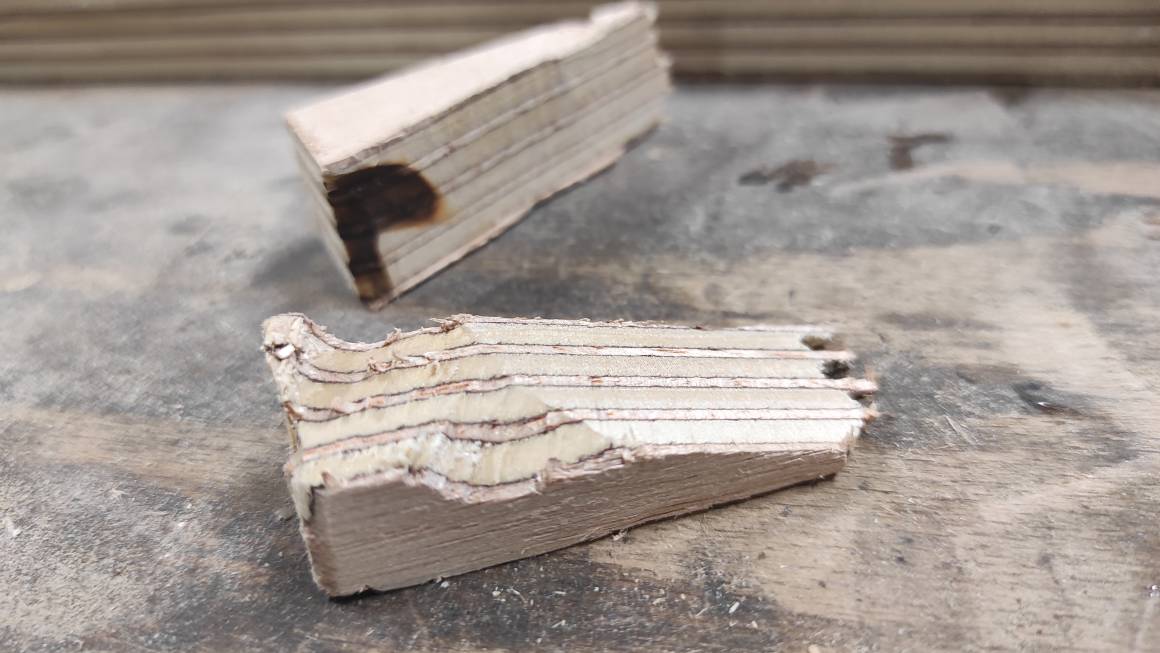
The other errors did not have significant consequences. Still during setting the Z origins, I often forgot to turn on the vaccuum table or turned on the dust aspiration instead and realized it almost immediately. ALso, I change the 6mm milling cutter for a 10 mm one to make faster production. When setting feed and speed in the tool library I forgot to change the ramp feedrate. The results was a big waste of time.
Late update
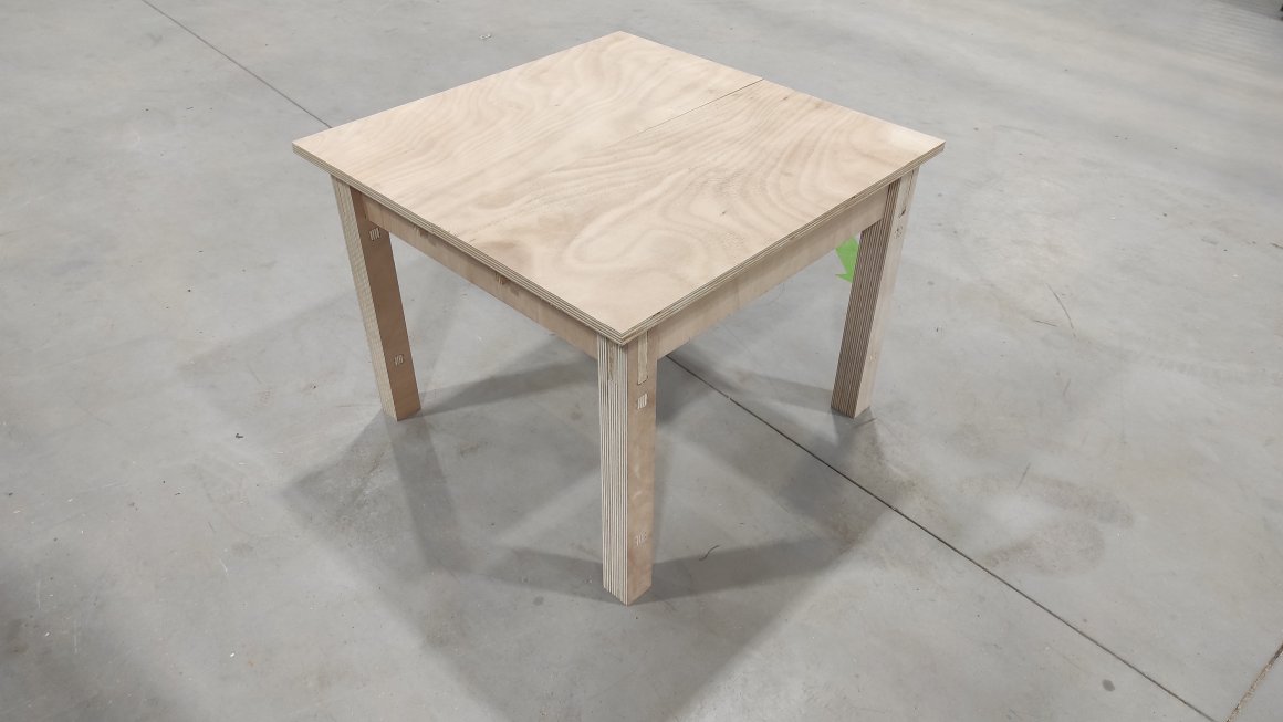
Until Week 10, I used some “free” time to finish my table. I’m quite satisfied of it but I should have added a slide for better stability, but I couldn’t figure out how to do it without fasteners. I still need to paint and varnish it.
Class Archive
- First version of the table Fusion File
- Final version of the table Fusion File
- Joint test Fusion file
- Table leg CAM File
- Table frame CAM File
- Tabletop CAM File
- Joint test Gcode Sorotec parameters
- Joint test Gcode CNCFraise parameters
- Table leg Gcode
- Table frame Gcode
Impressions of the week
The CNC machine is very impressive machine, with a lot of parameters to check and verified. It can be very stressful. It’s important to stay focus through the different steps. There’s a lot of missable step and working in pairs can prevent some of them. Working in a very noisy environment is also very tiring and favors errors over time. I still really enjoy designing in Fusion, and I feel that I improve especially doing parametric design but the Manufacture parameters are not always clear for me, but I learned more and more each time.