11. Input devices
Hero Shot
Assignment :
individual assignment:
- measure something: add a sensor to a microcontroller board that you have designed and read it
group assignment:
- probe an input device’s analog levels and digital signals
Group Assignment
You can find our group page here and this week group assignement here
Rotary encoder signals
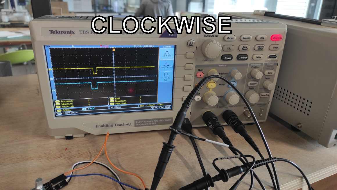
As I was testing programming a rotary encoder, I decided to probe it with an oscilloscope to visualize the digital signals of the 2 switch ccurring when turning it.
I connected CLK pin to the Channel 1 (yellow) and the DT pin to the Channel 2 (blue). When we turn the rotray encoder we see the signals going low for a moment with a slight timing difference.
we can see on this picture, DT changing before CLK when direction is clockwise and CLK before DT when direction is counter-clockwise.

Individual Assignment
For this week assignement, I used the devboard I designed during week09.
For my final project, I’d like to use switches and a selector but for this assignment, we had to use sensor to measure something. To fulfill it, I used DHT11 humidity/temperature sensor module breakout.
DHT11 - temperature and humidity sensor
My co-student Jean-Côme had already tested it during week 06 so I checked his documenation for inspiration as well as DHT11 Datsheet.
Unfortunately the datasheet differs from the breakout board, so I used another documentation
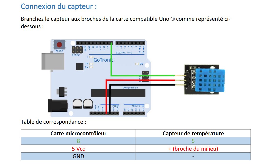
So, S pin is connected to an I/O pin, middle pin to 5V VCC and -(minus) pin to the ground.

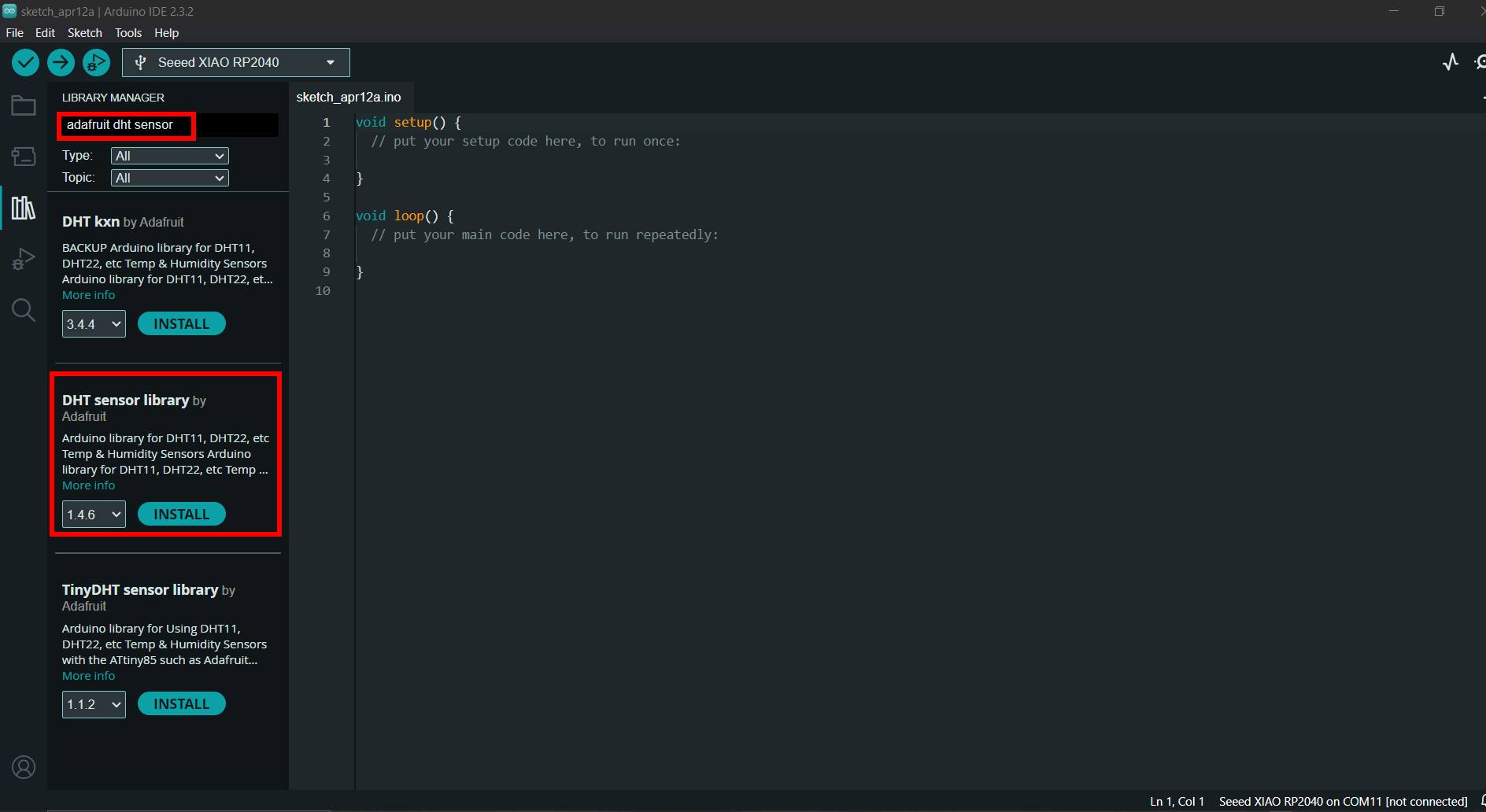
To program it in Arduino IDE, I needed the DHT Sensor Library
Using chatGPT, I generated a code to create a serial feedback of the sensor.
#include <DHT.h> // Using DHT Library

#define DHTPIN 26     // DHT11 I/O pin connected
#define DHTTYPE DHT11   // Sensor type (DHT11, DHT21, DHT22)

DHT dht(DHTPIN, DHTTYPE); // define DHT Object named 'dht' with previous define pin and type

void setup() {
Serial.begin(9600); // start serial communication with baud rate
dht.begin(); // start dht sensor read
}

void loop() {
delay(1000);  // wait 1 sec between each sensor read

// Reading DHT11 data
float humidity = dht.readHumidity();    // Read humidity in %
float temperature = dht.readTemperature();  // Read temperature in °C

// Checking if reading data succeed
if (isnan(humidity) || isnan(temperature)) { // if data read "is not a number"
    Serial.println("Failed to read DHT11 Sensor !"); //print on serial monitor error message
    return;
}

// Displaying data on serial monitor :
Serial.print("Humidity: ");
Serial.print(humidity);
Serial.print(" %\t");
Serial.print("Temperature: ");
Serial.print(temperature);
Serial.println(" °C");
}
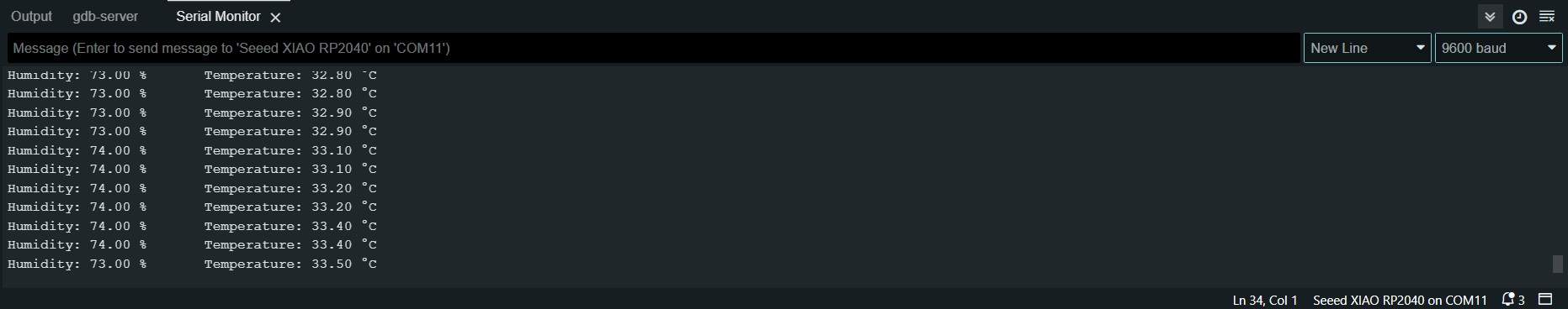
After uploading the program on the board, I get a feed back of the temperature and the humidity.
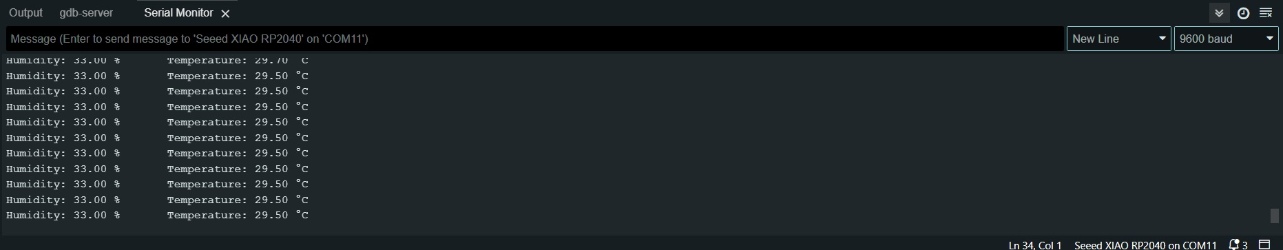
When I put the sensor in my hand, the serial monitor gavec me updated value (here after 20s and more)
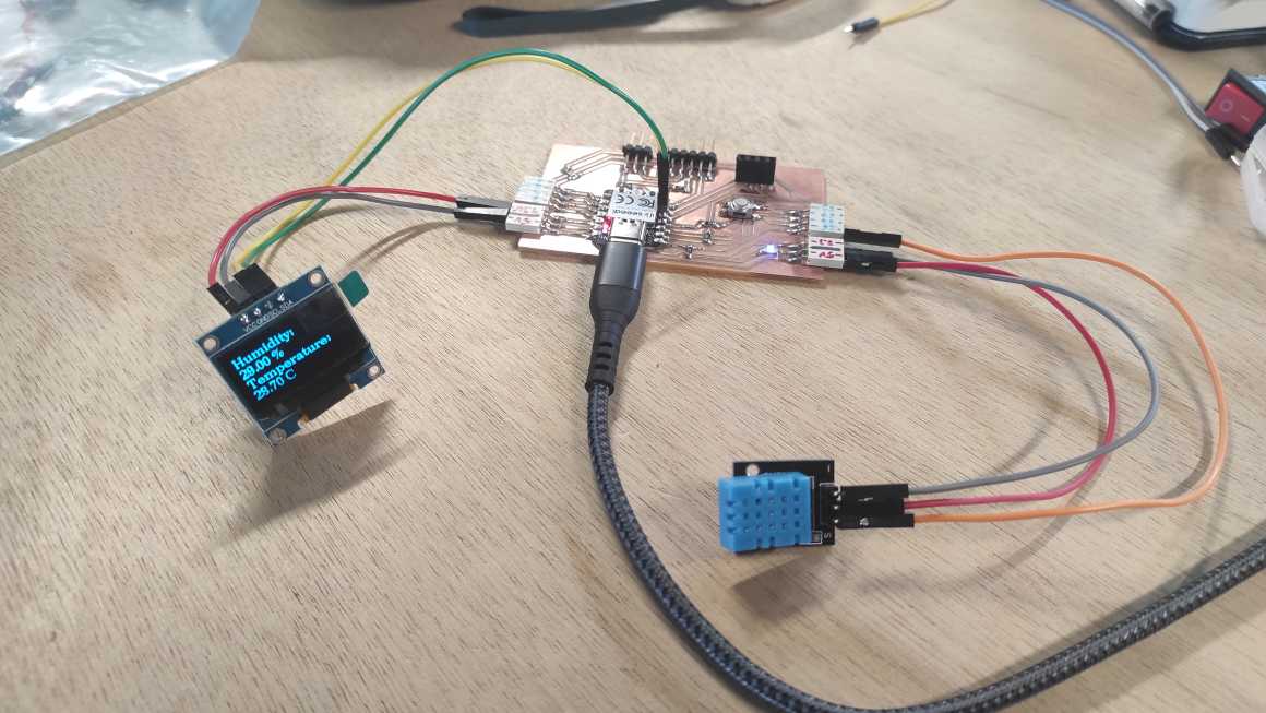
Combining it with my week 09 experiment, I should have been able to display the informations on an OLED screen. My I2C connector had broken during output device week so I used other pins for this test. I used pin 3 for clock and pin 4 for data
Somehow, I couldn’t make it work. My board didn’t recognize the I2C display, I tried different OLED screen, I also tried with the Quentorres. I also tried the previous code that worked but it didn’t worked this week. I tried the code is used to find I2C adresses but the code couldn’t find any display.
A couple of day later, I made another try on the Quentorres and all screens worked. I tried on my personnal board but it didnt work on the pin I previously chose. I decide to solder new connectors directly on pin 7 and 6 and I was finaly able to have a display on the screen.
I made a code using my previous test with OLED screen and mixing the two of them. Then I ask chat GPT how to change font size and how to display information on different line.
I ended with this code :
#include <DHT.h> // Using DHT Library
#include <U8g2lib.h>
#include <Wire.h>

#define DHTPIN 26     // DHT11 I/O pin connected
#define DHTTYPE DHT11   // Sensor type (DHT11, DHT21, DHT22)

DHT dht(DHTPIN, DHTTYPE); // define DHT Object named 'dht' with previous define pin and type

// OLED display constructor
U8G2_SSD1306_128X64_NONAME_F_HW_I2C u8g2(U8G2_R0, /* reset=*/ U8X8_PIN_NONE, /* clock=*/ 7, /* data=*/ 6);

void setup() {
Serial.begin(9600); // start serial communication with baud rate
dht.begin(); // start dht sensor read
u8g2.begin(); // Initialize the OLED display
}

void loop() {

u8g2.clearBuffer();
u8g2.setFont(u8g2_font_ncenB10_tr); // Set font and fontsize (10) and position
u8g2.setCursor(0, 15); // Set position (x, y)

delay(1000);  // wait 1 sec between each sensor read

// Reading DHT11 data
float humidity = dht.readHumidity();    // Read humidity in %
float temperature = dht.readTemperature();  // Read temperature in °C

// Checking if reading data succeed
if (isnan(humidity) || isnan(temperature)) { // if data read "is not a number"
    Serial.println("Failed to read DHT11 Sensor !"); //print on serial monitor error message
    return;
}

// Displaying data on serial monitor :
Serial.print("Humidity: ");
Serial.print(humidity);
Serial.print(" %\t");
Serial.print("Temperature: ");
Serial.print(temperature);
Serial.println(" °C");

    // Displaying data on OLED screen :
u8g2.print("Humidity: ");

u8g2.setFont(u8g2_font_ncenB10_tr); // Font size at 10
u8g2.setCursor(0, 30); // Set position (x, y) for changing lines

u8g2.print(humidity);
u8g2.print(" %\t");

// Set font and position for temperature
u8g2.setFont(u8g2_font_ncenB10_tr); // Font size at 10
u8g2.setCursor(0, 45); // Set position (x, y) for changing lines

u8g2.print("Temperature: ");

// Set font and position for temperature
u8g2.setFont(u8g2_font_ncenB10_tr); // Font size at 10
u8g2.setCursor(0, 60); // Set position (x, y) for changing lines

u8g2.print(temperature);
u8g2.println(" °C");


// Send the buffer to the display
u8g2.sendBuffer();
}
With this code, I was able to display all the information, using multiple lines.
KY-040 - Rotary Encoder
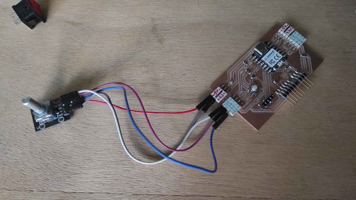
For my final project, I hesitated to use a rotary encoder instead of a potentiometer for better sensorial feedback as it is used as fidget too. To experiment with it, I found a KY-040 in Agrilab’s inventory.
I also checked the datasheet to undersatnd a bit how it works.
In summary, it essentially involves two switches that change state almost simultaneously but in a different order depending on whether the encoder is rotated clockwise or counterclockwise. There is also another switch on the shaft that simply open when you push on it. I also found out (a bit later) that default values is ‘High’ for all the switches.
There is five pins on the module :
- CLK is connected to switch A that change first when turning clockwise
- DT is connected to switch B that change first when turning counterclockwise
- SW is connected to the shaft switch
- ’+’ is connected to 5V VCC
- GND is connected to the ground
CLK, DT and SW don’t need to be connected to specific GPIO function.
Using chatGPT, i used this code :
#include <Arduino.h>

// Define the pins for the KY-040 rotary encoder
const int CLK_PIN = 26; // CLK pin connected to GPIO 26
const int DT_PIN = 27;  // DT pin connected to GPIO 27
const int SW_PIN = 28;  // SW pin connected to GPIO 28

// Variables to store the previous state of the CLK and DT pins
int prevCLKState = LOW;
int prevDTState = LOW;

void setup() {
// Set the pins as inputs with internal pull-up resistors enabled
pinMode(CLK_PIN, INPUT_PULLUP);
pinMode(DT_PIN, INPUT_PULLUP);
pinMode(SW_PIN, INPUT_PULLUP);

// Start serial communication
Serial.begin(9600);
}

void loop() {
// Read the state of the CLK and DT pins
int CLKState = digitalRead(CLK_PIN);
int DTState = digitalRead(DT_PIN);

// Check for clockwise rotation
if (CLKState != prevCLKState && CLKState == HIGH) {
    if (DTState == LOW) {
    Serial.println("Clockwise");
    }
}

// Check for counter-clockwise rotation
if (DTState != prevDTState && DTState == HIGH) {
    if (CLKState == LOW) {
    Serial.println("Counter-clockwise");
    }
}

// Check if the switch is pressed
if (digitalRead(SW_PIN) == LOW) {
    Serial.println("Button pressed");
}

// Update the previous state variables
prevCLKState = CLKState;
prevDTState = DTState;

// Add a small delay to debounce the switch
delay(10);
}
Unfortunately, the serial monitor didn’t return the correct information. Turning clockwise and pushing on the shaft workes but turning counterclockwise returned “clockwise”.
I tried some other code but chatGPT seemed to have issues to know how theKY040 works. I aknowledged it with what I learned from the datasheet. I also tried to feed it with code I found online but I couldn’t succeed. I thought maybe the selector didn’t work as it was supposed to be.
With the help of a French Website “Passion Electronique”, I decided to test the device to understand how it really works.
Using a breadboard, I made a small circuit with LEDs to see how the they light when I use the encoder.
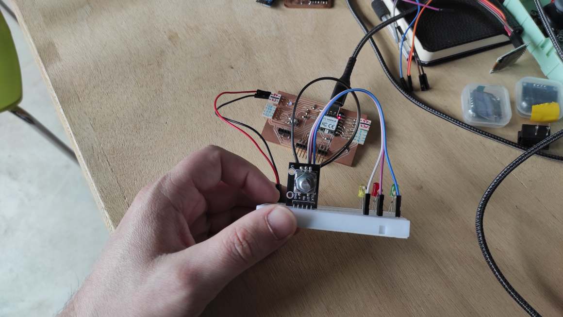

Using it, I found out that the switches A and B are always LOW at each step and turns on and off between each step. Until this moment, I thought them changing state at each step. Being very slow between 2 steps, I also found out that DT turns on before CLK when the encoder is turned clockwise and CLK turns on before DT when turned counter-clockwise. All that is different from the datasheet I found before.
I struggled a lot to find a good way to program it. I tried a lot of prompts to make chatGPT create a good one. I make a lot of test and finally found out my circuitdesign messed it up. I went back to the program proposed on passion electronique. Changing pins permit to increment and decrement properly. I used INPUT_PULLUP instead of INPUT when defining pinMode for SW pin because it was bouncing or maybe floating is the right way to describe it.
Also, from my previous experiment, I had to change change the code because DT lower before CLK on my rotary encoder, contrary of the code provided. Instead of inverting CLK DT in all the code, I just inverted the count++ en count--.
Serial Monitor Result
Here is the final code :
#define pinCLK 1       // CLK pin connected to GPIO 1
#define pinDT  2       // DT pin connected to GPIO 2
#define pinSW  3       // SW pin connected to GPIO 3

int count = 0;    // Var to know how many clicks occured (increment clockwise and decrement counter_clockwise)
int previousStateSW;           // Var to memorize previous SW state to compare it with actual state
int previousStateCLK;          // Var to memorize previous CL state to compare it with actual state

void setup() {

    Serial.begin(9600);

    pinMode(pinSW, INPUT_PULLUP);         // INPUT_PULLUP to avoid 'floating'
    pinMode(pinDT, INPUT);
    pinMode(pinCLK, INPUT);

    previousStateSW  = digitalRead(pinSW);    // initial value for SW
    previousStateCLK = digitalRead(pinCLK);   // initial value for CLK

    delay(200); // delay to stabilize signal before the loop
}

void loop() {

    int actualStateCLK = digitalRead(pinCLK); // reading CLK value
    int actualStateDT  = digitalRead(pinDT);  // reading DT value
    int actualStateSW  = digitalRead(pinSW);  // reading SW value

// *************************
// Push Button verification
// *************************

    if(actualStateSW != previousStateSW) {    // Checking if SW state has changed
        previousStateSW = actualStateSW;      // Save new state

        if(actualStateSW == LOW)
            Serial.println(F("SW Button pushed"));     // Display State on serial monitor
        else
            Serial.println(F("SW Button released"));

        delay(10); // Delay to avoid rebounce
    }

// ***************************
// Rotary encoder verification
// ***************************

    if(actualStateCLK != previousStateCLK) {       // Checking if SW state has changed
    previousStateCLK = actualStateCLK;           // Save new state

    if(actualStateCLK == LOW) {

        if(actualStateCLK != actualStateDT) {   // comparing CLK and DT, if they're different, direction is counter-clockwise
            count--;                            // decrement counter
            Serial.print(F("Direction = clockwise | Counter value = "));   // Display value on Serial Monitor
            Serial.println(count);
        }
        else {                                   // when CLK and DT are similar, direction is clockwise
            count++;                             // increment counter
            Serial.print(F("Direction = counter-clockwise | Counter value = "));   // Display value on Serial Monitor
            Serial.println(count);
        }

        delay(1);   // delay to avoid CLK rebounce
    }
    }

}
Here is the result on serial monitor :
We can see some bouncing value during rotation. Using chatGPT, I tried to add some debounce but couldn’t make it work. On the contrary, it was worst than no debounce at all.
Following the Passion electronique tutorial, the autor advise to add RC filters (resistor/condensator) to the circuit.

I didn’t get time to test it this week, but I absolutely keep that in mind for my final project.
OLED screen result
Despite that and having my OLED screen problem resolved, I tried to display the information on a screen. I ended up with this code :
#define pinCLK 1       // CLK pin connected to GPIO 1
#define pinDT  2       // DT pin connected to GPIO 2
#define pinSW  3       // SW pin connected to GPIO 3

#include <U8g2lib.h>
#include <Wire.h>

// OLED display constructor
U8G2_SSD1306_128X64_NONAME_F_HW_I2C u8g2(U8G2_R0, /* reset=*/ U8X8_PIN_NONE, /* clock=*/ 7, /* data=*/ 6);

int count = 0;    // Var to know how many clicks occured (increment clockwise and decrement counter_clockwise)
int previousStateSW;           // Var to memorize previous SW state to compare it with actual state
int previousStateCLK;          // Var to memorize previous CL state to compare it with actual state

void setup() {

    Serial.begin(9600);

    // Initialize the OLED display
    u8g2.begin();

    pinMode(pinSW, INPUT_PULLUP);         // INPUT_PULLUP to avoid 'floating'
    pinMode(pinDT, INPUT);
    pinMode(pinCLK, INPUT);

    previousStateSW  = digitalRead(pinSW);    // initial value for SW
    previousStateCLK = digitalRead(pinCLK);   // initial value for CLK

    delay(200); // delay to stabilize signal before the loop
}

void loop() {

    int actualStateCLK = digitalRead(pinCLK); // reading CLK value
    int actualStateDT  = digitalRead(pinDT);  // reading DT value
    int actualStateSW  = digitalRead(pinSW);  // reading SW value

    // Clear the screen
    u8g2.clearBuffer();

    // *************************
    // Push Button verification
    // *************************

    if (actualStateSW != previousStateSW) {    // Checking if SW state has changed
        previousStateSW = actualStateSW;      // Save new state

        if (actualStateSW == LOW) {
            Serial.println(F("SW Button pushed"));     // Display State on serial monitor

            // Set font and position
            u8g2.setFont(u8g2_font_ncenB14_tr);
            u8g2.setCursor(0, 20); // Set position (x, y)
            // Write text to the screen
            u8g2.print("SW Button :");

            u8g2.setCursor(0, 40); // Set position (x, y)
            // Write text to the screen
            u8g2.print("Pushed");

        } else {
            Serial.println(F("SW Button released"));

            u8g2.setFont(u8g2_font_ncenB14_tr);
            u8g2.setCursor(0, 20); // Set position (x, y)
            // Write text to the screen
            u8g2.print("SW Button :");

            u8g2.setCursor(0, 40); // Set position (x, y)
            // Write text to the screen
            u8g2.print("Released");
        }
        // Send the buffer to the display
        u8g2.sendBuffer();

        delay(10); // Delay to avoid rebounce
    }

    // ***************************
    // Rotary encoder verification
    // ***************************

    if (actualStateCLK != previousStateCLK) {       // Checking if SW state has changed
        previousStateCLK = actualStateCLK;           // Save new state

        if (actualStateCLK == LOW) {

            if (actualStateCLK != actualStateDT) {   // comparing CLK and DT, if they're different, direction is counter-clockwise
                count--;                            // decrement counter
                Serial.print(F("Direction = counter-clockwise | Counter value = "));   // Display value on Serial Monitor
                Serial.println(count);

                u8g2.setFont(u8g2_font_ncenB10_tr);
                u8g2.setCursor(0, 15); // Set position (x, y)

                // Write text to the screen
                u8g2.print("Direction :");

                u8g2.setFont(u8g2_font_ncenB08_tr);
                u8g2.setCursor(0, 28); // Set position (x, y)
                u8g2.print("counter-clockwise");

                u8g2.setFont(u8g2_font_ncenB10_tr);
                u8g2.setCursor(0, 45); // Set position (x, y)
                // Write text to the screen
                u8g2.print("Counter value = ");

                u8g2.setCursor(0, 60); // Set position (x, y)
                u8g2.println(count);

                // Send the buffer to the display
                u8g2.sendBuffer();
            }
            else {                                   // when CLK and DT are similar, direction is clockwise
                count++;                             // increment counter
                Serial.print(F("Direction = clockwise | Counter value = "));   // Display value on Serial Monitor
                Serial.println(count);

                 u8g2.setFont(u8g2_font_ncenB10_tr);
                u8g2.setCursor(0, 15); // Set position (x, y)

                // Write text to the screen
                u8g2.print("Direction :");


                u8g2.setCursor(0, 30); // Set position (x, y)
                u8g2.print("clockwise");

                u8g2.setCursor(0, 45); // Set position (x, y)
                // Write text to the screen
                u8g2.print("Counter value = ");

                u8g2.setCursor(0, 60); // Set position (x, y)
                u8g2.println(count);

                // Send the buffer to the display
                u8g2.sendBuffer();
            }

            delay(1);   // delay to avoid CLK rebounce
        }
    }
}
The results was very satisfactory.
Class Archive
- Arduino code for DHT11 sensor
- Arduino code for DHT11 sensor + OLED display (u8g2)
- Arduino code for KY-040 rotary encoder
- Arduino code for KY-040 rotary encoder + OLED display (u8g2)
Global Review
This week, my work has been reviewed by Neil. Click on the image to watch it.
Impressions of the week
This week went quite right. Soon, I completed the required assignments so I could focus on my final project input tests. I spent quite a lot of time testing the rotary encoder and I’m satisfied with what I learned from it. I still see a lot of improvement to make it work consistently. Also, I’m annoyed that some test I made during previous week didn’t work anymore. I really spend a lot of time again to find a solution that I’m not completely satisfied with.