6. Embedded programming
Hero Shot
Assignment :
Individual assignment:
- write a program for a microcontroller development board that you made, to interact (with local input &/or output devices) and communicate (with remote wired or wireless devices)
- extra credit: use different languages &/or development environments
- extra credit: connect external components to the board
Group assignment:
- browse through the data sheet for your microcontroller
- compare the performance and development workflows for other architectures
Group Work
You can find our group page here and this week group assignement here
Comparing Micro-controller
We chose to make a table to compare 2 micro-controller chips using datasheets and vendor documentations :
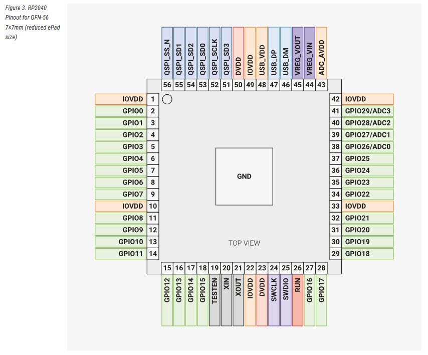
| Feature | RP2040 | ESP32 - S3 |
|---|---|---|
| Processor | Dual-Core ARM Cortex MO+ | Xtensa Dual-core 32bits LX7 |
| Clock speed | 133 Mhz | 2.4 GHz |
| Memory | 264kb SRAM & 2MB Flash | 512Kb SRAM & 384 Kb ROM |
| GPIO pins | 30 | 30 |
| Serial Interface | Brown-out Detect/Reset, DMA, I2S, LCD, POR, PWM, WDT | ADC, I2C, I2S, SDIO, SPI, PWM, UART |
| Analog inputs | 4 | 20 |
| Connectivity | None | Bluetooth 4.2 & WiFi 802.11b/g/n |
| Cost | 70ct | 1.85$ |
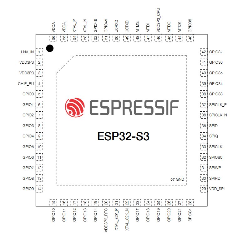
| Size | 7x7 mmm | 5x5 mm |
Here’s a representation of the I/O pins for each chips :
Our boards use XIAO RP2040 which is a micro-controller board using the RP2040 chip. The functionalities are slightly different such as an USB-C connector for programming and power supply.
Writing a program
Hardware
As a complete newcomer in electronics, I had a lot of informations to explore to understand the Neil’s course. I read some documentations in english and in french :
- MTM Micro-controller Primer
- AWS information page about micro-controllers(in french)
- AWS information page about CPU (in french)
- digitalworld article938
- and some wikipedia pages
For our programming, we use a micro-controller. Micro-controller is like tiny computer with much less power. It’s a micro-chip that contains microprocessors, RAM (temporary memory), ROM (long-term memory) and peripherals with internal bus (electrical connexions to send and receive datas) to interact together.
I had troubles with my board, making all thing functionning as I wished.
I spend lot of time debugging, first by using basic programming to test elements. All my LED cold blink as tested in Week04.
When I tested the button example, it only worked with the LED on pin 1.
To check what’s wrong, I add the digitalRead example to the button to verify the response on the button. It worked normally for pin 1 LED, but for the other the LEDs remained off but the serial monitor displayed “1” when the button was pushed and stayed at 1 after releasing it. It returned to 0 by moving it slightly. I concluded I had a problem with the button and solder a new one, but the problems still occured. Manipulating the board for visual check, a wire has become unsoldered.
I decided to make a new board from scratch cause I had also LEDs not lighting at the same level.
Hopefully, we had already mill a PCB in prevision of that kinf of issue.
I was more confident in my soldering skill and it went quite okay. After testing it, I stil had a problem with the button not working. I learned to test it with the multimeter an evreything seemed alright. My Co-student Jean-Côme help me with visual check and find that my soldering on the pin 27 wasn’t good enough. Resoldering it solve the problem.
Programming
Using Arduino IDE, I try several examples to comprehend base programming. We also had a base programming workshop, in which we use some examples and were teached about the meaning of the code. I checked Arduino Language reference page to understand and describe the code.
Example test
First we define values:
This line set the number of the LED pin :
const int pinLed = 26 ;
const stands for constant and means that the value won’t change.-
int stands for integers and means the data types is a number
- pinLed can be replaced by another word like led1 if you need more led for example.
- the number stand for the actual pin your LED is connected on the micro-controller
We can set this constant with another comand :
#define led1 26
Don’t use
;at the end of the line. It might generate errors.
For variables, you don’t write const
int buttonState = 0
Then, we define setup for our program. This part will be run only once.
void setup() {
  pinMode(led1, OUTPUT);
}
- “Void” means no information is expected to be extracted from this code, if it’s called by another code.
pinModeis used to configure the pin with the pin number and its type, input or output.- the pin number here refers to the constant we define earlier, so the pin 26.
So, in a little more complex code, here from a button example :
const int buttonPin = 27;  // the number of the pushbutton pin
const int led1 = 1;   // the number of the LED pin

// variables will change:
int buttonState = 0;  // variable for reading the pushbutton status

void setup() {
   // initialize serial communication at 9600 bits per second:
  Serial.begin(9600);
  // initialize the LED pin as an output:
  pinMode(led1, OUTPUT);
  // initialize the pushbutton pin as an input:
  pinMode(buttonPin, INPUT);
}
Serialis used for communication between the computer and the microcontroller. It is used in this code to have a feedback on the serialmonitor.Serial.beginis used to define the speed of that communication. It is set at 9600 bps by defaults.buttonPinconstant is screated at value 27, and led1 constant is created at 1- a variable named
buttonStateis created with initial value at 0 - pin 1 is set as an output through the
led1constant and pin 27 is set as an input through thebuttonPinconstant
Now the main code :
void loop() {
  // read the state of the pushbutton value:
  buttonState = digitalRead(buttonPin);

  // check if the pushbutton is pressed. If it is, the buttonState is HIGH:
  if (buttonState == HIGH) {
    // turn LED on:
    digitalWrite(led1, HIGH);
  } else {
    // turn LED off:
    digitalWrite(led1, LOW);
  }

  Serial.println(buttonState);
  delay(1);
}
- ``void loop” define the main code that will run repeatedly.
buttonStateis a new variable.digitalReadis a function that will read the value of digital pin, whether the current is passing or not. It will set the variable as HIGH or LOW and equivalent 1 or 0 if the button is pushed or not. -ifis a structure to check a condition (here(buttonState == HIGH),==comparing the 2 variables and returning ‘true’ if they’re equal) and executes the following statement if the condition is ‘true’. -elsecomplete theifstructure to define statement if the the previous condition returns ‘false’digitalWriteis set as statements and is a function that will command if a pin will be powered or not, HIGH or LOW.Serial.printlnis function to print data (here the buttonState value, ‘1’ or ‘0’) in the serial port like the serialMonitor in ArduinoIDE.delayis a time function to pause the program, to let a command to be executed for examples. Here it’s probably to limit the number of prints in the serial monitor. It is set on this example at 1 ms.
Aternating LEDs
Now starting with a specific code. Using chat GPT, I write the prompt :
write a code for arduino : with a button, pushed once, light a led ; pushed twice, light a second led ( but don’t light the first) , pushed 3 times light the third led.
Chat GPT provided this code I will explain part after part:
const int buttonPin = 27;  // the number of the pushbutton pin
const int ledPin1 = 26;    // the number of the first LED pin
const int ledPin2 = 0;    // the number of the second LED pin
const int ledPin3 = 1;    // the number of the third LED pin
int buttonState = 0;  // variable for reading the pushbutton status
int lastButtonState = 0; // variable to store the previous state of the button
unsigned long lastDebounceTime = 0;  // the last time the output pin was toggled
unsigned long debounceDelay = 50;    // the debounce time; increase if the output flickers
In this part, we found the previous buttonState variable, plus a new variable to emplement the number of push “lastButtonState”.
unsigned long is used for variables that need big number (4 bytes or 32 bits) and is used for 2 new variables : lastDebounceTime and debounceDelay. Those ares used to avoid spurious transition when pressing the button. The delay is set at 50 ms and will be compare to the lastDebounceTime using a function that we will see further.
void setup() {
  pinMode(buttonPin, INPUT);
  pinMode(ledPin1, OUTPUT);
  pinMode(ledPin2, OUTPUT);
  pinMode(ledPin3, OUTPUT);
  // Initialize serial communication:
  Serial.begin(9600);
}
Now the main code :
void loop() {
  // read the state of the pushbutton value:
  int reading = digitalRead(buttonPin);

  // check if the button state has changed
  if (reading != lastButtonState) {
    // reset the debouncing timer
    lastDebounceTime = millis();
  }

  // if a certain amount of time has passed since the last change
  if ((millis() - lastDebounceTime) > debounceDelay) {
    // if the button state has changed
    if (reading != buttonState) {
      buttonState = reading;

      // check if the button is pressed
      if (buttonState == HIGH) {
        // increment LED count
        static int ledCount = 0;
        ledCount++;

        // turn off all LEDs
        digitalWrite(ledPin1, LOW);
        digitalWrite(ledPin2, LOW);
        digitalWrite(ledPin3, LOW);

        // light LEDs according to button presses
        if (ledCount == 1) {
          digitalWrite(ledPin1, HIGH);
          Serial.println("First LED on");
        } else if (ledCount == 2) {
          digitalWrite(ledPin2, HIGH);
          Serial.println("Second LED on");
        } else if (ledCount >= 3) {
          digitalWrite(ledPin3, HIGH);
          Serial.println("Third LED on");
          // reset LED count after lighting the third LED
          ledCount = 0;
        }
      }
    }
  }

  // save the current button state for comparison in the next loop iteration
  lastButtonState = reading;
}
reading for checking the buttonPin value.
Then it creates a new value for lastDebounceTime. If reading is different from previous lastButtonState, lastDebounceTime is state as millis (a function that return the number of milliseconds since the starting of the program).
Then, if a change occurs in the reading (and different of buttonState) in a time (millis-lastDebounceTime) superior to the debounceDelay, it will change the buttonState to match reading. Thats how debounce works to avoid spurious transitions.
then it can check the buttonState, and create a variable ledCount that increment 1 each time the button is pushed.
For each value of ledCount, it starts LEDs off and turns a specific LEDS on. If the counter reaches 3, it also reset the counter to 0.
It finally set the lastButtonState to match reading value`.
As I wanted the LED to turn off when the cycle reaches an end, I added a fourth state to the led counter for turning off the third LED. I also modified the comparators >= for == on the the ledCount 3 condition because there is now a superior value.
You can find the complete code in this ino file (the ino file needs to be in a folder of the same name to be open with ArduinoIDE).
Press duration button
For this test, I also used chatGPT 3.5 with the prompt :
write a code for arduino : if I hold the button 1 it lights the first LED ; if i hold it longer til 2s, the second leds is added; 3s the third LED is added and 4s all leds turns off
const int buttonPin = 27;    // the number of the pushbutton pin
const int ledPin1 = 26;      // the number of the first LED pin
const int ledPin2 = 0;      // the number of the second LED pin
const int ledPin3 = 1;      // the number of the third LED pin

int buttonState = 0;        // variable for reading the pushbutton status
int lastButtonState = 0;    // variable to store the previous state of the button
unsigned long pressStartTime = 0; // variable to store the time when button was pressed
unsigned long pressDuration = 0;  // variable to store the duration of button press

void setup() {
  pinMode(buttonPin, INPUT);
  pinMode(ledPin1, OUTPUT);
  pinMode(ledPin2, OUTPUT);
  pinMode(ledPin3, OUTPUT);
  // Initialize serial communication:
  Serial.begin(9600);
}

void loop() {
  // read the state of the pushbutton value:
  int reading = digitalRead(buttonPin);

  // check if the button state has changed
  if (reading != lastButtonState) {
    // reset the debouncing timer
    pressStartTime = millis();
  }

  // if the button is pressed
  if (reading == HIGH) {
    pressDuration = millis() - pressStartTime;

    if (pressDuration >= 1000 && pressDuration < 2000) {
      digitalWrite(ledPin1, HIGH);
    }
    else if (pressDuration >= 2000 && pressDuration < 3000) {
      digitalWrite(ledPin2, HIGH);
    }
    else if (pressDuration >= 3000 && pressDuration < 4000) {
      digitalWrite(ledPin3, HIGH);
    }
    else if (pressDuration >= 4000) {
      digitalWrite(ledPin1, LOW);
      digitalWrite(ledPin2, LOW);
      digitalWrite(ledPin3, LOW);
    }
  }
  else {
    // if the button is released, turn off all LEDs
    digitalWrite(ledPin1, LOW);
    digitalWrite(ledPin2, LOW);
    digitalWrite(ledPin3, LOW);
  }

  // save the current button state for comparison in the next loop iteration
  lastButtonState = reading;
}
The condition compare pressDuration to specific values to turn LEDs on: between 1 and 2 s, between 2 and 3, 3 and 4 then 4 or more.
For more reactivity, I changed the condition value to start 1s faster. Also, I deleted the last else structure to keep the LEDs on after releasing the button.
The final program is available as ino file (the ino file needs to be in a folder of the same name to be open with ArduinoIDE).
Potentiometer test
For my final project, I’d like to use a potentiometer or a selector. I chose to test potentiometer programming for now.
To test a potentiometer on my board, I first needed to define the 3 pin of the potentiometer. Using a multimeter, I measured the resistance between the pin. Between the external, I had a fixed resistance of 9.64 Ohm even if I turned the potentiometer. This means those are the positive and the negative terminals.
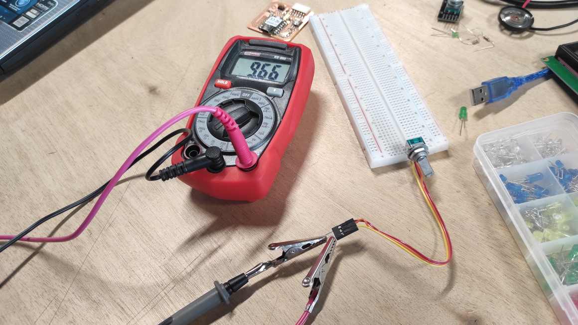
Measuring between the central pin and an external one, I can observe changes on the resistance. If, when i turn the potentiometer clockwise, the resistance is raising, it’s connected to the positive terminal. If it’s lowering, it’s the negative terminal
Checking on documentation, I found that there is 4 analog pins (ACD inputs) on the RP2040. A0 and A1 are already used for a LED and the button as GPIO 26 and 27. Section 2.9.5 describe that this pin can be powered between 1.8V and 3.3V.
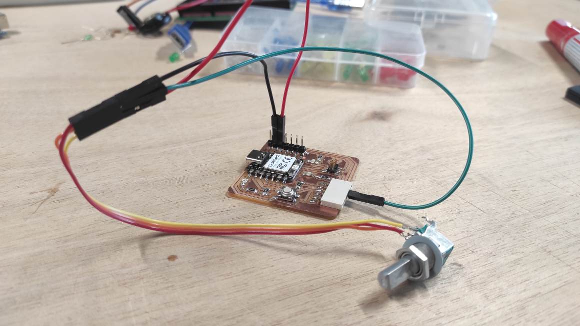
To connect it to my board, I added connexion header on it to have a better access at the 3.3V pin.
A2 and A3 are available but A3 is link to a 1000 ohms resistor. Potentiometer being a variable resistor, I thought using the pin without resistor was more pertinent. But after testing the two of them, they both works well.
I made this setup.
ChatGPT provided me this code to this prompt and some specification to correct issues:
make an arduino code for a potentiometer lighting 1 then 2 then 3 led as it is turn.
const int potPin = A2;  // analog pin for the potentiometer
const int ledPin1 = 26;  // the number of the first LED pin
const int ledPin2 = 0;  // the number of the second LED pin
const int ledPin3 = 1;  // the number of the third LED pin
const int numLEDs = 3;  // number of LEDs

void setup() {
  pinMode(ledPin1, OUTPUT);
  pinMode(ledPin2, OUTPUT);
  pinMode(ledPin3, OUTPUT);
}

void loop() {
  // Read the potentiometer value
  int potValue = analogRead(potPin);

  // Map the potentiometer value to the range of LEDs
  int ledLevel = map(potValue, 0, 1023, 0, numLEDs + 1);

  // Turn on the LEDs based on the mapped value
  digitalWrite(ledPin1, ledLevel >= 1);
  digitalWrite(ledPin2, ledLevel >= 2);
  digitalWrite(ledPin3, ledLevel >= 3);

  delay(100);  // Adjust delay as needed to control the responsiveness
}
potPin constant define the Analog pin on A2 and don’t need to be set as input in the setup part.In the main program,
analogRead will get a value between 0 and 1023 from the potentiometer and make a variable from it.
Then it creates from it a ledLevel variable with the map functions. This functions will make corresponding potValue (between 0 and 1023) and ledLevel (between 0 and 4 “pinLEd+1”)
Then it will turn on LED for each ledLevel, corresponding to the potentionmeter value.
The final code is here
Serial Analog test
I also test AnalogInOutSerial example to have a monitor feedback of the value of the potentiometer.

I change the code a bit to turn on all LEDs with the fade.
The final code is here
Class Archive
ino file needs to be in a folder of the same name to be open with ArduinoIDE
- Alternating LEDs code ino file
- Press Duration code ino file
- Potentiometer with levels of LED on code ino file
- Analog read and write serial + fade code ino file
Impressions of the week
I found the data sheets quite overwhelming and I still have lots af questions about it. There’s a lot of acronyms I don’t understand yet and some I misinterpreted. I still have a lot to acquire in this department. I did soldering again and I was more comfortable this time. For programming, I took lot of time to understand what was written, and I feel quite confident to modify it for what I want. Intricated functions continues to make my brain hurts but I somehow understand what I’m doing. Having a good results on the board is rather satisfactory.