9. Output devices
Hero Shot

Assignment :
Individual assignment:
- add an output device to a microcontroller board you’ve designed, and program it to do something
Group assignment:
- measure the power consumption of an output device
Group Assignment
You can find our group page here and this week group assignement here
Fan Power consumption
For group assignment, I’ve tested Power consumption of a fan, I set Voltage at 12V as stated on the device. I added current progressively and the fan started to turn at 0.231 A and then the current drop under 0.170 A.
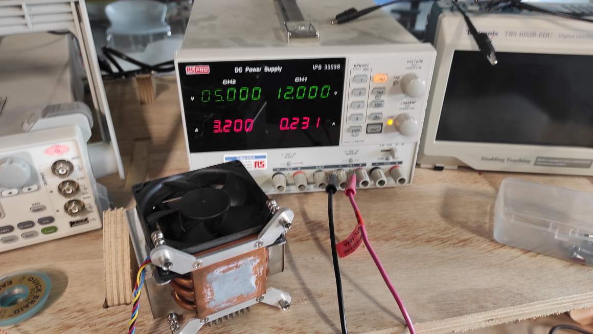
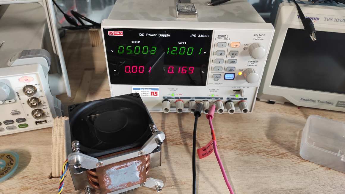
I lowered the current after that and the fan still turns but much slower.

I also tested augmenting the Voltage up to 13 V and it’s making the fan turning faster.
Individual Assignment
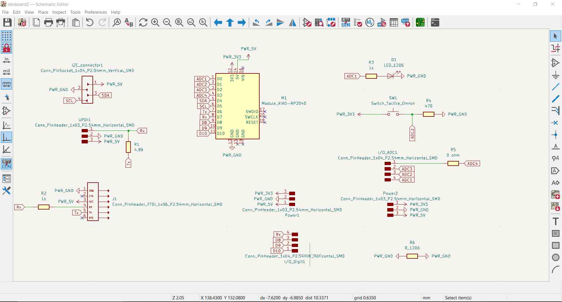
New devboard
As I failed to program my board on Electronics Design week, I decided to redesigned an easier to program board around the RP2040 microboard to fulfill the next weeks assignements. Having an embedded USB connectors should help a lot to program it.
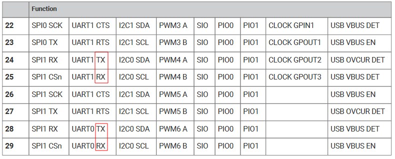
I used Adrian Torres Documentation in Quentorres page to define the pin I needed on the microboard. I was disturbed by the UART connectors using the pins 28 and 29 while the documentation states Tx and Rx being on pin 0 and 1. I found in the RP2040 datasheet those pins and all the GPIO can be programmed for a specific UART one among other possibilities.


I decides to design it with I2C, UART, UDPI and I/O connectors. I added an LED and a button for testing purposes.

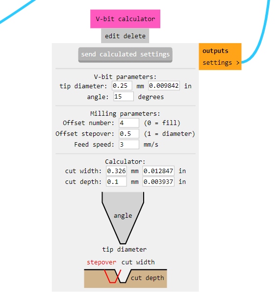
I milled the PCB with the Tapered ball nose mill using parameters Pol-Emile sent me. As his milling went pretty well at 2mm/s, I increased it at 3 mm/s. Here are my parameters.
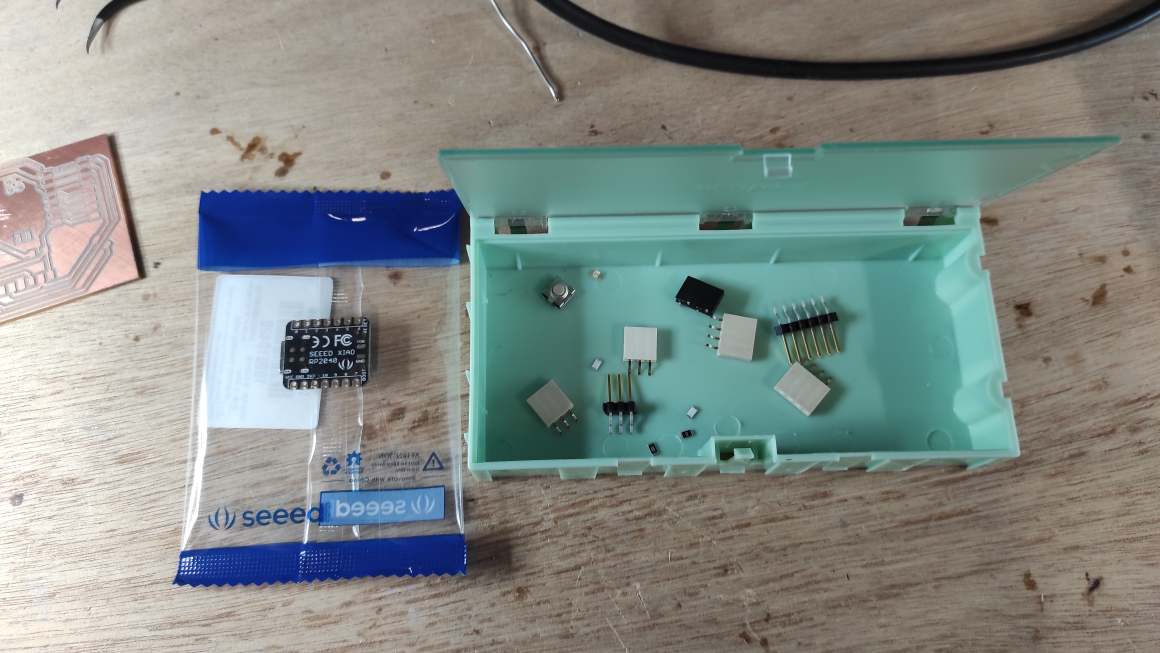
Time to solder again !

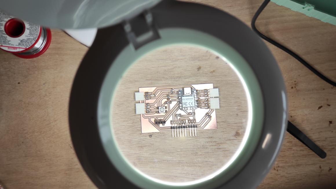
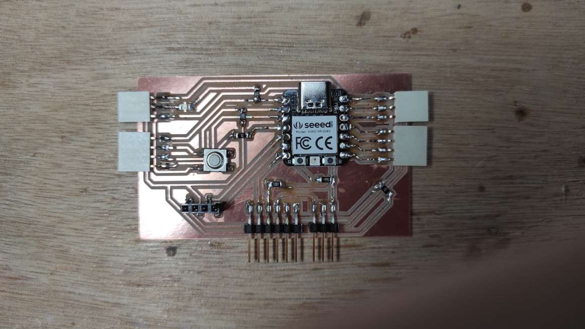
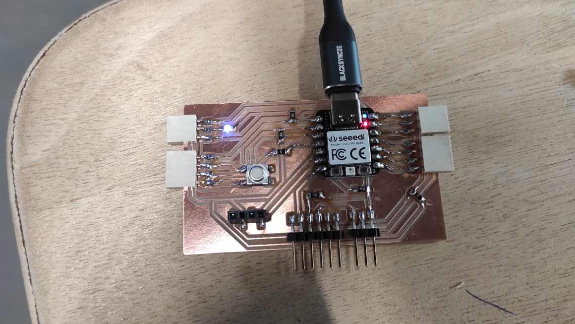
Testing the board, I could have my LED blinking and the button returns information in serial monitor.
OLED Screen
For testing an OLED screen, I used the SSD1306 screen with the U8g2 library as recommended in Neil’s documentation.

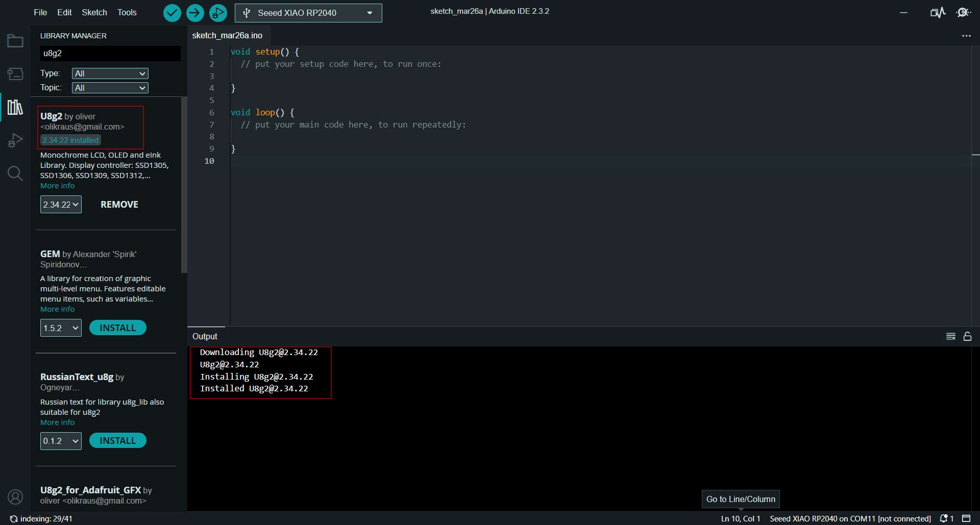
I used chat GPT to generate a code to display a text. I modified it a little to set the pins SDA and SCL and change the default text.
Here’s the final code :
#include <U8g2lib.h>
#include <Wire.h>

// OLED display constructor
U8G2_SSD1306_128X64_NONAME_F_HW_I2C u8g2(U8G2_R0, /* reset=*/ U8X8_PIN_NONE, /* clock=*/ 7, /* data=*/ 6);

void setup(void) {
  // Initialize the OLED display
  u8g2.begin();
}

void loop(void) {
  // Clear the screen
  u8g2.clearBuffer();

  // Set font and position
  u8g2.setFont(u8g2_font_ncenB14_tr);
  u8g2.setCursor(0, 20); // Set position (x, y)

  // Write text to the screen
  u8g2.print("It works! _o/");

  // Send the buffer to the display
  u8g2.sendBuffer();

  // Delay to control the refresh rate
  delay(1000);
}
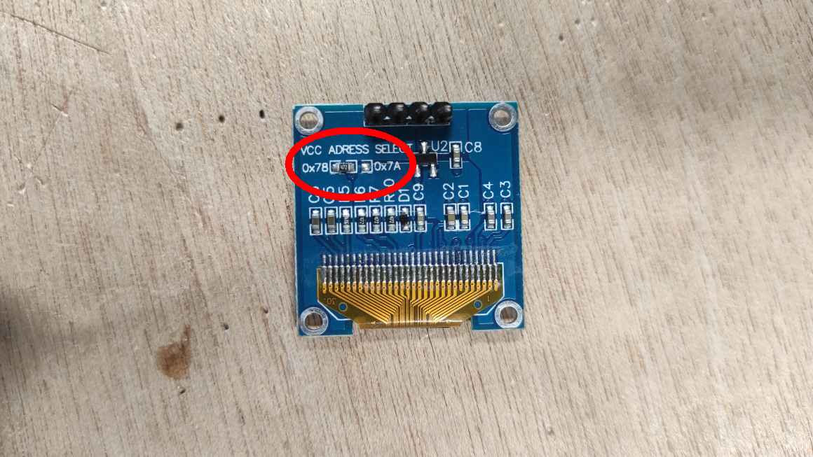
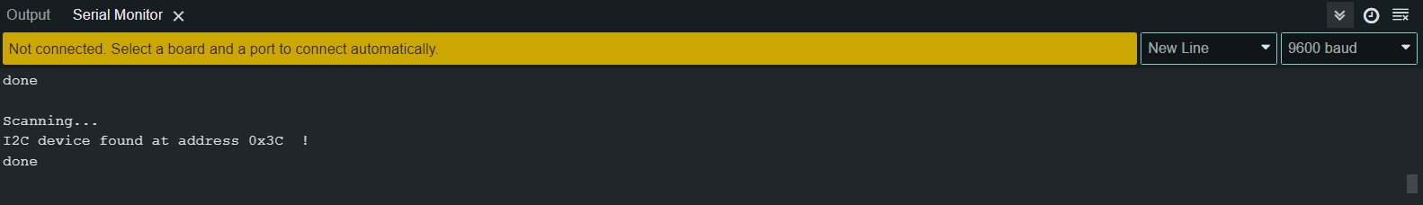
I also generated a code to scan the I2C adress of a screen. This can be useful for uses with other libraries like Adafruit. We thought the adress was on the back of the OLED screen but Luc proposed me to check with a program.
#include <Wire.h>

void setup() {
  Wire.begin();

  Serial.begin(9600);
  while (!Serial);

  Serial.println("\nI2C Scanner");
}

void loop() {
  byte error, address;
  int nDevices;

  Serial.println("Scanning...");

  nDevices = 0;
  for (address = 1; address < 127; address++) {
    // The i2c_scanner uses the return value of
    // the Write.endTransmisstion to see if
    // a device did acknowledge to the address.
    Wire.beginTransmission(address);
    error = Wire.endTransmission();

    if (error == 0) {
      Serial.print("I2C device found at address 0x");
      if (address < 16) {
        Serial.print("0");
      }
      Serial.print(address, HEX);
      Serial.println("  !");

      nDevices++;
    } else if (error == 4) {
      Serial.print("Unknown error at address 0x");
      if (address < 16) {
        Serial.print("0");
      }
      Serial.println(address, HEX);
    }
  }

  if (nDevices == 0) {
    Serial.println("No I2C devices found\n");
  } else {
    Serial.println("done\n");
  }

  delay(5000); // wait 5 seconds for next scan
}
The serial monitor returned me a different adress at 0x3C.
Unfortunately, my I2C connector broke but I learned from datasheet that all of the pins have a functions for I2C. I noticed that not all kind of characters are displayed. I could explore that later. I also should explore image displaying.
DC Motor
For testing a DC motor, I used a TTmotors.
It can be powered with 3 to 6 V.
I also used an MD13S Motor driver that was already connected to it by Jean-Côme. It permits to invert the current and change the direction the motor rotate. It uses 3 pins for that, one connected to the ground, one to a PWM pin (to modulate the speed), one DIR pin connected to a digital pin (0 is a direction, 1 is the other). As we were numerous in the Electrolab, I didn’t have access to a Bench Power Supply. I was told that I could use 3x18650 Battery Holder to power it. It makes a lot of tension (11.2V) compared to the Datasheet recommandations but the motor had handle it.

Again, I used chatGPT to generate a code. I had to make changes to make it adapt to the driver and because i mistook it for an H-bridge at first.
// Define the pins for the MD13S Motor Driver
const int pwmPin = 26;  // PWM pin for motor speed control (connect to MD13S pin PWM)
const int dirPin = 27;   // Direction pin for motor control (connect to MD13S pin dir)

void setup() {
  // Set the control pins as outputs
  pinMode(pwmPin, OUTPUT);
  pinMode(dirPin, OUTPUT);
}

void loop() {
  // Move the motor forward
  digitalWrite(dirPin, HIGH);  // Set direction to forward
  analogWrite(pwmPin, 255);    // Set speed to maximum
  delay(2000);                  // Delay for 2 seconds

  // Stop the motor
  analogWrite(pwmPin, 0);      // Set speed to 0
  delay(1000);                  // Delay for 1 second

  // Move the motor backward
  digitalWrite(dirPin, LOW);   // Set direction to backward
  analogWrite(pwmPin, 255);    // Set speed to maximum
  delay(2000);                  // Delay for 2 seconds

  // Stop the motor
  analogWrite(pwmPin, 0);      // Set speed to 0
  delay(1000);                  // Delay for 1 second
}
Servomotor
I tried Tower Pro Micro Servo 9g SG90. Documentation mentions 4.8V operating Voltage. I found more documentations on vendor website (in french) about voltage being up to 7.2V and components101 give me some informations for wiring.

I generated a code with ChatGPT and modify some delay to change the speed of movement.
#include <Servo.h>

Servo servoMotor;  // Servo object

void setup() {
  servoMotor.attach(26);  // Attach the servo to pin 6
}

void loop() {
  // Rotate the servo from 0 to 180 degrees
  for (int angle = 0; angle <= 180; angle++) {
    servoMotor.write(angle);  // Set the servo angle
    delay(5);  // Short delay for smoother movement
  }
  delay(1000);  // Wait for a second at the end of the movement

  // Rotate the servo from 180 to 0 degrees
  for (int angle = 180; angle >= 0; angle--) {
    servoMotor.write(angle);  // Set the servo angle
    delay(15);  // Short delay for smoother movement
  }
  delay(1000);  // Wait for a second at the end of the movement
}
Unfortunately, the servo only move on an angle aroung 90° beside 180°. I tried different servos in case it was broken. I change the code for a loop with just servo Motor.write(0) and servo Motor.write(180) with a delay but i couldn’t make it work.
Again, I’ll try to find time later to understand what was going on.
Class Archive
- Personal Devboard 2 Kicad Schematics & PCB
- Personal Devboard 2 SVG traces & interior
- Personal Devboard 2 RML traces & interior
Impressions of the week
I spend much time trying to understand why my last week board can’t be programmed. I didn’t succeed and with only two days left for this week assignment. I decided to make an easier to program board with the Xiao RP2040 microboard. Hopefully, it worked right and i could fulfill my assignement in time. I’d hope to have more time to test more deeply the output I used and I regret I didn’t have enough time to test e-paper for my final project and stepper motor for machine week and to learn more about MOSFET and H-bridge.