11. Output devices
Amsterdam, April 15, 2020
To do
| Description | status |
|---|---|
| Group assignment: | done |
| Pick an output device | done |
| Design a board with an output device | done |
| Make a board from the design | done |
| Program the board | done |
Source files
| Description | link |
|---|---|
| Arduino I2Cscanner example code for the monitor | Downloadable zip. |
| KiCad files for OLED monitor board | Downloadable zip. |
| Monitor board traces | Downloadable PNG |
| Monitor board cutout | Downloadable PNG |
| Neil’s Hello Echo code for the ATtiny3216 | zipped .ino file |
| Adafruit example code for OLED monitor | zipped .ino file |
urls
| Description | link |
|---|---|
| Index of this week’s topic | http://academy.cba.mit.edu/classes/output_devices/index.html |
| Global lecture video | https://vimeo.com/408128983 |
| Global review video | https://vimeo.com/412495560 |
| Recitation video | https://vimeo.com/409904934 |
| Group assignment documentation | http://fabacademy.org/2020/labs/waag/groupAssignments/week11.html |
| FabLab inventory list | https://docs.google.com/spreadsheets/d/1U-jcBWOJEjBT5A0N84IUubtcHKMEMtndQPLCkZCkVsU/edit#gid=0 |
| Mods testing environment | http://mods.cba.mit.edu/ |
| Neil’s Hello Echo code for the ATtiny3216 | http://academy.cba.mit.edu/classes/embedded_programming/t3216/hello.t3216.echo.ino |
Group assignment
A full description of the group assignment can be found on our communual page.
Assignment: Measure the power consumption of an output device.
How to measure the power consumption
Since we don’t have access to our lab because of the Covid-19 we looked into three methods of measuring the current:
- Use a multimeter (in Amp setting) in series with the project
- Use a multimeter (in Voltage setting) and use an one ohm resistor in series and measure the voltage over the resistor
- Use an arduino to measure voltage and use a one ohm resistor in series and measure the voltage over the resistor
Since we had no 1 ohm resistor, we tested with a multimeter in Amps settings. We used two output devices, a 28byj-48 stepper motor and an SSD1306 128x64 OLED.
Output device 1. Stepper motor
First, we connected a stepper motor to a stepper motor driver and an Arduino board. Then, we connected a multimeter between 5V power source and the motor in series.
The current measured when the motor was running on its maximum speed was 184.4mA. The voltage was 5V, so we could calculate that the power was 5V * 0.1844A = 0.922W.
P= V * I = 5v * 0.1844A = 0.922W
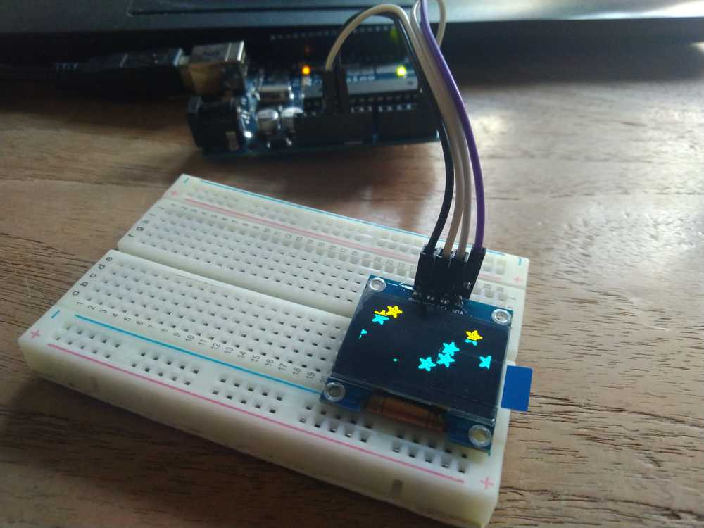
Output device 2. SSD1306 128x64 OLED
We used the SSD1306 128x64 OLED display and the example code from the Adafruit library. After downloading the libraries, these can be found at File > Example > Adafruit SSD1306 >128x64 i2C.
This file runs with images of different size and varying brightness, so current varied while the code was running, and the multimeter displayed readings of between 3mA and 14mA.
P= V * I = 5v * 0.003A = 0.015W P= V * I = 5v * 0.014A = 0.21W
What I learned
To be frank, this time the group assignment went a bit past me. We were working remote and I did not have a multimeter. I watched as Harm, Hyejin and Nathan figured out and accomplished the group assignment. What I learned is that you can put the multimeter in series with your project. That means that you put the two probes in between a circuit of your device. For instance by unplugging a wire and connect the probe to it. At this point you can read out the multimeter. Then you can apply the math formula’s above to calculate the Watts.
Later in the week I made use of the multimeter at the Lab in the context of my individual assignment and I am now convinced of the usefullness of the device and will buy one. Once I have it I will redo this group assignment because as it stands now my contribution was very very meagre.
It’s now one weak later and my multimeter has arrived in the mail. I will now do the group assignment.
I use the Arduino and the OLED monitor for testing
- Measuring Volts
- I looked at this tutorial. Steps:
- 1. Set the multimeter to Voltage setting and in this case to Direct Current.
- 2. The tutorial says to select the ‘appropriate voltage range’. I look up what that is. Sparkfun advises to first try measuring a battery. I do and get 1.5V. Place the black GND probe to GND (-) and the red probe to VCC. Should you do it the other way around, no problem, you just get a negative voltage reading. As ever, Sparkfun comes with a clear explanation. Here is they explain the ‘appropriate voltage range’.
- ‘Set the knob to “20V” in the DC range (the DC Voltage range has a V with a straight line next to it). Multimeters are generally not autoranging. You have to set the multimeter to a range that it can measure. For example, 2V measures voltages up to 2 volts, and 20V measures voltages up to 20 volts. So if you’ve measuring a 12V battery, use the 20V setting. 5V system? Use the 20V setting. If you set it incorrectly, you will probably see the meter screen change and then read ‘1’.’
My Voltcraft VC165 has autorange, so I don’t have to select the voltage range.
3. I place the black probe on the GND pin of the Arduino pin where the GND wire of the monitor is connected. I place the red probe on VCC. My readout is 3.29V.
Measuring Current
Again with the help of Sparkfun.
1. Make sure your black GND pprobe is placed in the GND port of the multimeter (it’s called COM in my case). The red probe should go to the port labeled mA/uA. (You only use the 10Amax setting if your device uses close to 200mA or more.)
2. As a starting point put the dial on the mA setting.
3. To measure current you must measure in series. You can’t poke the probe at a protruding piece of solder. You have to get in between the circuit. I use wires to break out the VCC and crocodile clips to connect that the protruding VCC wires to the probes.
4. Keep in mind that in a 5V project a reading of 7 to 8mA is expected under normal 5V conditions.
My readout is 2mA.
- A warning from Sparkfun:
- Remember! When you’re done using the meter, always return the meter to read voltage (return the probes to the voltage port, set the meter to read the DC voltage range if necessary). It’s common to grab a meter and begin to quickly measure the voltage between two pins. If you have left your meter in ‘current’ mode, you won’t see the voltage on the display. Instead you’ll see ‘0.000’ indicating that there is no current between VCC and GND. Within that split second you will have connected VCC to GND through your meter and the 200mA fuse will blow = not good. So before you put the meter down for the night, remember to leave your meter in a friendly state.
Calculating power consumption
The formula to calculate power consumption is:
P = V * I
I need to remind myself:
Voltage = V
Current = I (measured in Ampere)
Resistance = R
Power = P (measured in Watts)
The readout was 3.29 V and 2mA
So 3.29V * 0.002A = 0.0066W. This is less than Nathan’s readout, who also measured the OLED monitor. But he was running Adafruit’s exampke code that runs stars across the screen. My monitor was simply outputting a statis ‘Hello World’.
Output device: OLED monitor
I choose a monitor because I will use it in my final assignment. I choose the OLED because it looks better than LED monitors. I don’t need all the extra capabilities of TFT monitors.
I looked at Neil’s OLED board. Spent quite some time figuring out what the SSD1306 component mentioned in his traces file should look like in KiCad. The monitor is not a part of the Fab symbol library in KiCad nor in the other libraries. Looking through several students previous projects like that of Henk and Deb it started to dawn on me that it is a simple 1x4_header. This is used to connect the four pins of the monitor to the board. You can’t see it in Neil’s video but I think he uses a female header because the monitor is ‘clicked’ onto the board. Others like Deb used a male header and used wires to connect the the board pins and the monitor pins.
At this moment I don’t know yet how to get the particular footprint for the header. I would expect four islands in a row. But both Neil and Deb have a different footprint in which the islands are stepped.
Arduino
I wanted to make Neil’s OLED board that uses an ATtiny45 to get started. The input week has made me weary of starting out too ambitious and becoming lost at sea. But Henk said to do a board with more flash memory. The ATtiny45 does not have enough storage for Arduino libraries so if you use an ATtiny45 you’ll have to code in C. And there is more documentation on the other. more powerful ATtiny’s, then there is on coding for the OLED in C. That makes sense but again, if there isn’t much previous documentation I fear I will get lost.
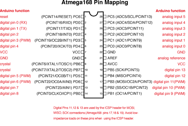
So I decided to start even simpler with an Arduino. I have a Arduino Diecimila, it is based on the ATmega168.
I followed this tutorial. And I had to check the pinout for this particular Arduino.
Here is an image of the pinout of the Diecimila.
Settings:
tool > board > Diecimila
tools > processor > Atmega168
tools > port /dev/ttyUSB0
tools > programmer > Arduino as ISP.
I uploaded the code referred to by the tutorial. This code scans the I2C bus for devices. When it is found it reports it to the Arduino serial monitor.
It worked and the monitor output is:
Scanning...
I2C device found at address 0x3C  !
done
I need to add two Adafruit libraries: the Adafruit_SSD1306 and the Adafruit-GFX-library. You can do this by going to sketch > include library > manage libraries. Type in the name of the library and it is found. In this case it prompted it also needed to install other libraries for the primary library to work. Clicked ok.
Under file > examples > Adafruit SSD1306 there are a couple of example code options. ssd_1306128x32_I2C, or ssd_1306128x64_I2C. The monitor I have was part of the electronics kit Henk gave us when the the corona lockdown started. The component does not say specifically what it is. So I am going to guess that it’s the SSD1306 from the Fab inventory and that is the SSD 1306 128 x 64 I2C 0.96 inch.
I try to upload the example sketch but the sketch is too big for the Diecimila.
I went and got another Arduino. So many resources :). I repeated the procedures of first uploading the address scanner and then uploaded the Adafruit example code. And it works.
Choosing the microcontroller
The Adafruit code and libraries are a little over 20Kb. That means I have a choice to make. Either I build a board with a powerfull microcontroller like the ATtiny 3216 that has 32 Kb memory and I can use the Adafruit code. Or I use a less powerfull microntroller like the ATtiny44 with 4 Kb memory and then I have to code in C. The 3216 needs to be programmed with a UPDI and I have not done that yet. Coding in C for the OLED also seems daunting. Neither option will be easy, so I am going to go with what I want to learn this week. And I choose to go with the harder board and the easier code. And then in another week I will go for the coding.
Later in the week, after I had finished designing the board, I found out that the Adafruit code is exceptionally large. There are other OLED libraries that aren’t quite so big like Tiny4kOLED.h. Adafruit has all kinds of excess functionalities like making stars. If you use smaller code you can run the OLED on an ATtiny85 board.
Making the schematic
I used Neil’s ATtiny45 board as an example for the components that I need.
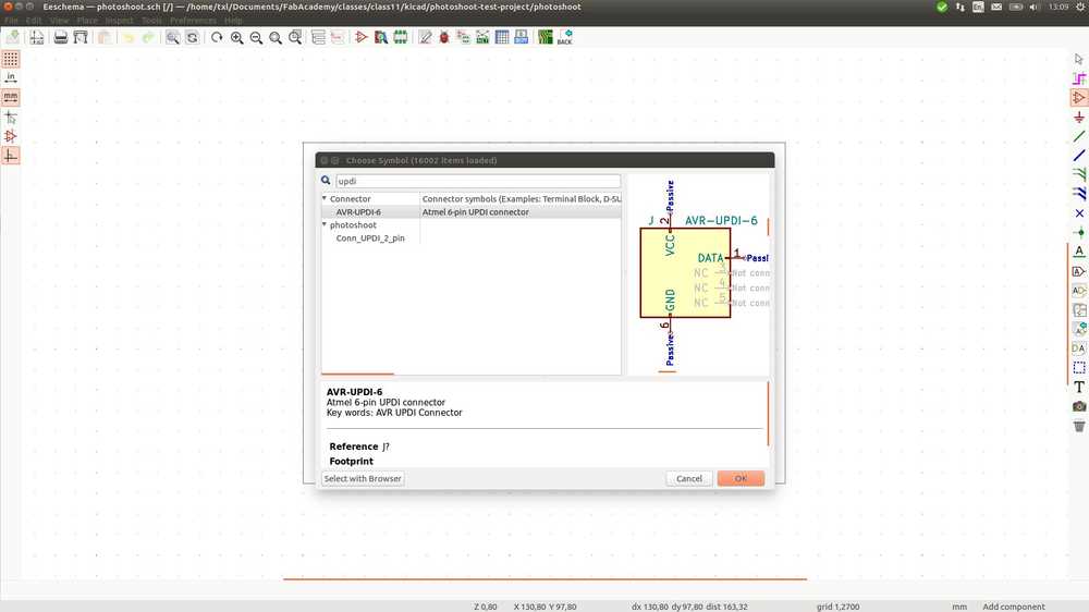
Adding a symbol to KiCad
Instead of an ISP pin header I need a UPDI pin. That’s a two header horizontal pin. This isn’t in the symbol library. On Hyejin’s page she explains super clearly how to do this. After to the symbol you also need to make a footprint.
I follow Hyejin’s directions here:
- In the KiCad workbench (so not the Eschema workbench) go to tools > edit schematic symbols. The
Symbol Editoropens. - In the Editor go to File > New library. (Don’t put them in an existing library as it may mess up the library).
- Choose global or local library.
- click create new symbol. The icon on the left, not the ‘new symbol’ under file. Icon most left:
- It prompts you to choose a library. Choose the library you just created.
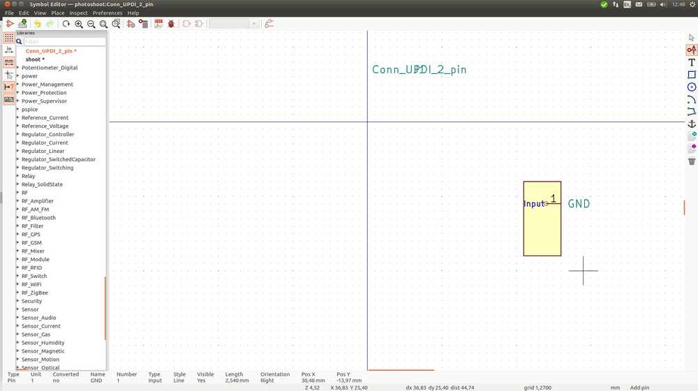
- Give the new symbol a name (Conn_UPDI_2_pin_vertical_SMD)
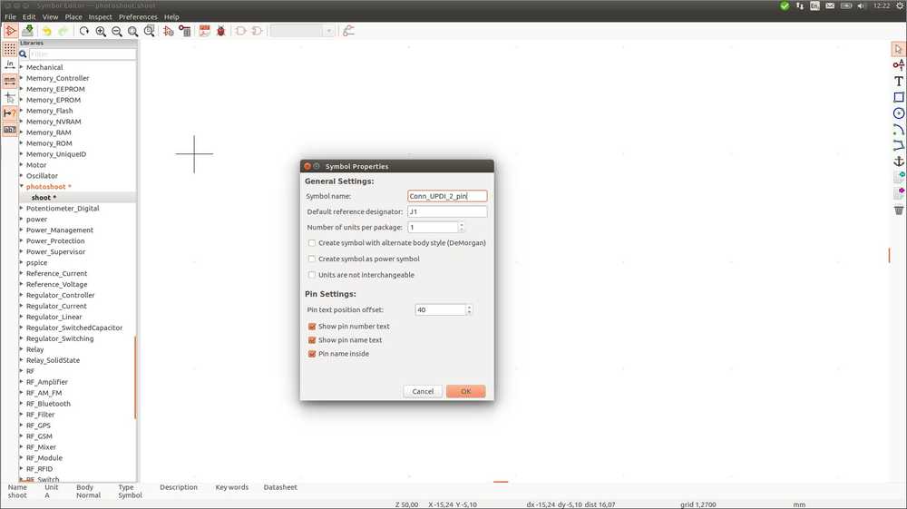
- Draw a component with the tools on the left of the panel.

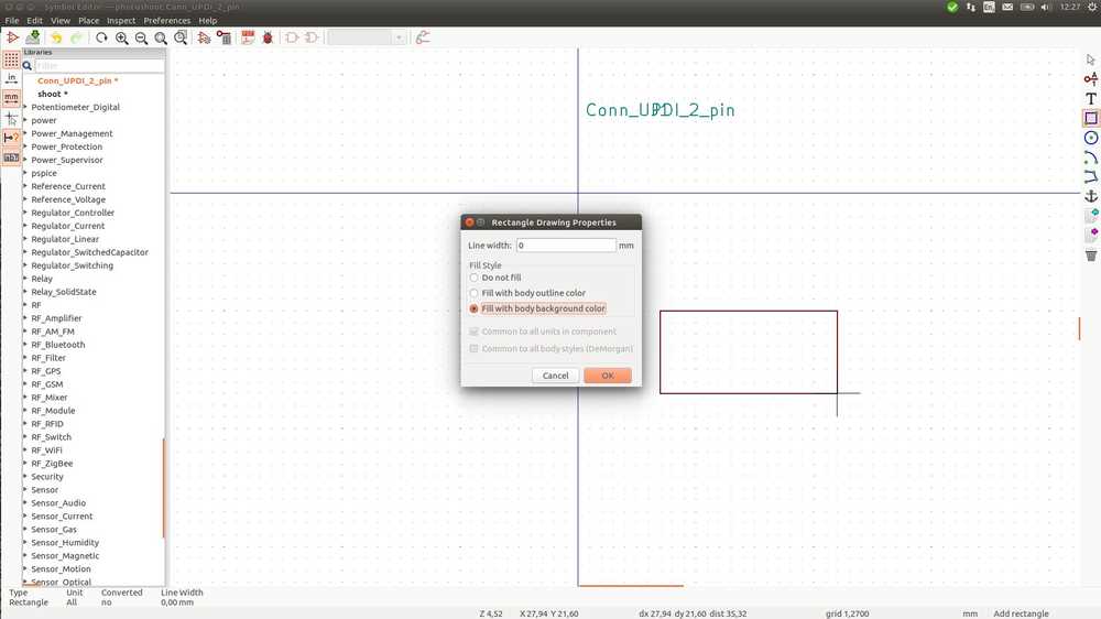
- When you select the rectangle tool & right-click you can add background color. To start drawing with the rectangle tool, select it, then click on the sketch and then you can start drawing.
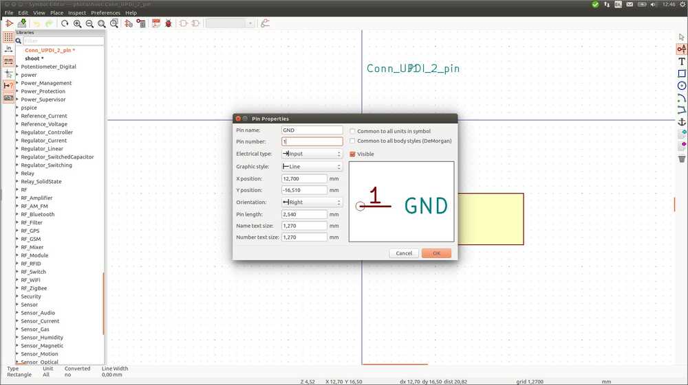
- Add pins with the pin icon.

- Save changes. When you go back to EEschema and click the
new symbolicon, you should be able to find the component in the Symbols library.
 But now comes the hard part: to add a footprint. It isn’t hard to do in KiCad, Hyejin explains this very good too. But what is the footprint. You need to know the dimensions of the packaging of the component. After some searching I think that the SMD packaging has 2.54 mm.
Adding a footprint to KiCad
- In the KiCad workbench (so not the Eschema workbench) go to tools > edit PCB footprints.
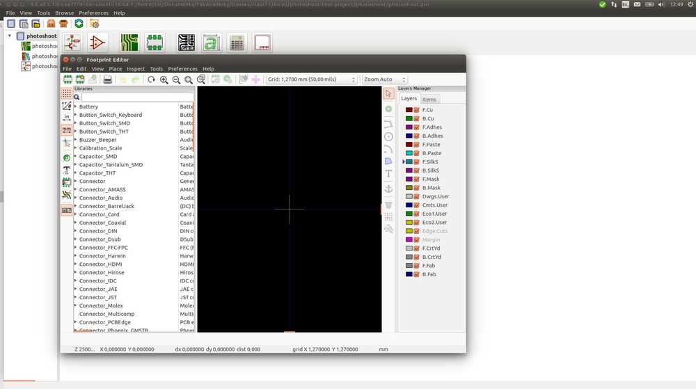
- Go to File > New library. (Don’t put them in an existing library as it may mess up the library).
- Choose global or local library.
- File > new footprint. Give it a name.
- Add components: under place > add pad for instance.
Added name and a pad:
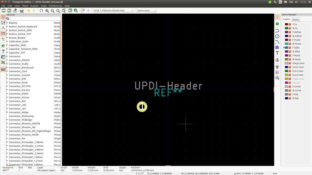
- Then right-click on the newly added component and click properties. I changed from through-hole to SMD & from round to rounded rectangular.
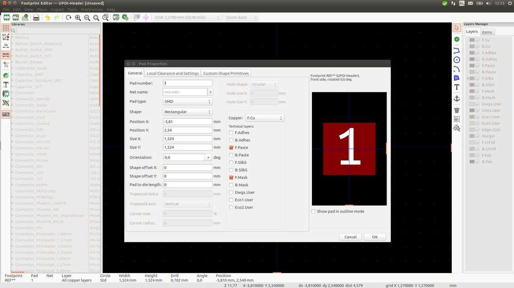
- There you can also set the size. I measured the pads of an FTDI header, it’s about 1,2 by 2.5. And since I see the number 2.54 everywhere I am going to use that.
- Determining the distance between the pads is a bit of a work around. Under View > grid settings, set the grid to the distance you want to accomplish. Then ‘Select the grid to be exactly 2.54 millimeters.
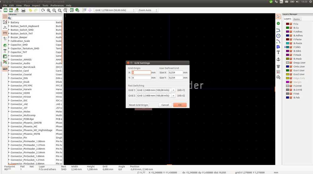
Now, we can start adding pins right on top of the grid dots and they will be spaced at exactly 2.54 millimeters apart.’ Source In my case, when I selected theadd pad iconit would inherit th eproperties from the previous pad I had created. When hovering over the grid, the pad would snap to the grid points. With the grid set to 2.54mm, the pads are placed exactly that far apart.
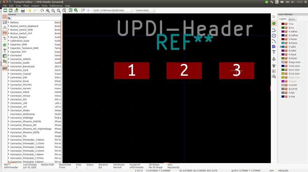
- To double check, you can select a component and at the bottom of the panel you can see its position. You can place the first pad on the origin: right-click and choose
position relative toand chooseuse local origin.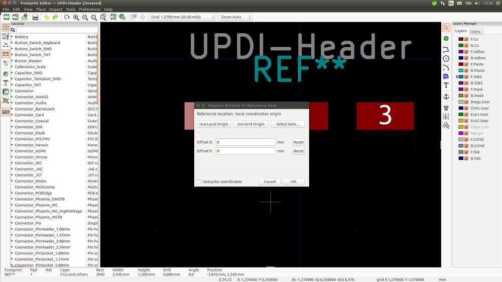 you can tell the distance by clicking on the other. (I know realize you can also determine the distance in the properties box by filling in the X-Y positions.)
Note X and Y positions at the bottom f the panel.

- Save the footprint in the new library you made. (new_footprint.pretty).
- To use your footprint go to EEschema workbench and click the sympbol you created. Then click the
assign pcb footprints icon
- The
assign footprintswindow opens. in the middle select the symbol you want to add a footprint to.
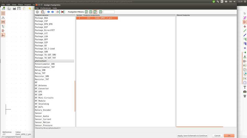 On the left choose your library.
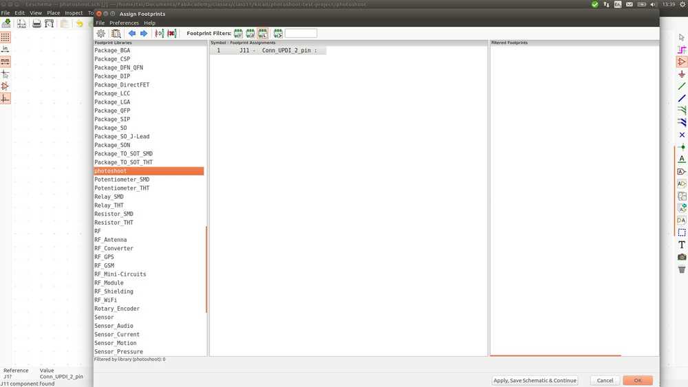 On the right your footprint appears. (If it does not, check if you saved it.)
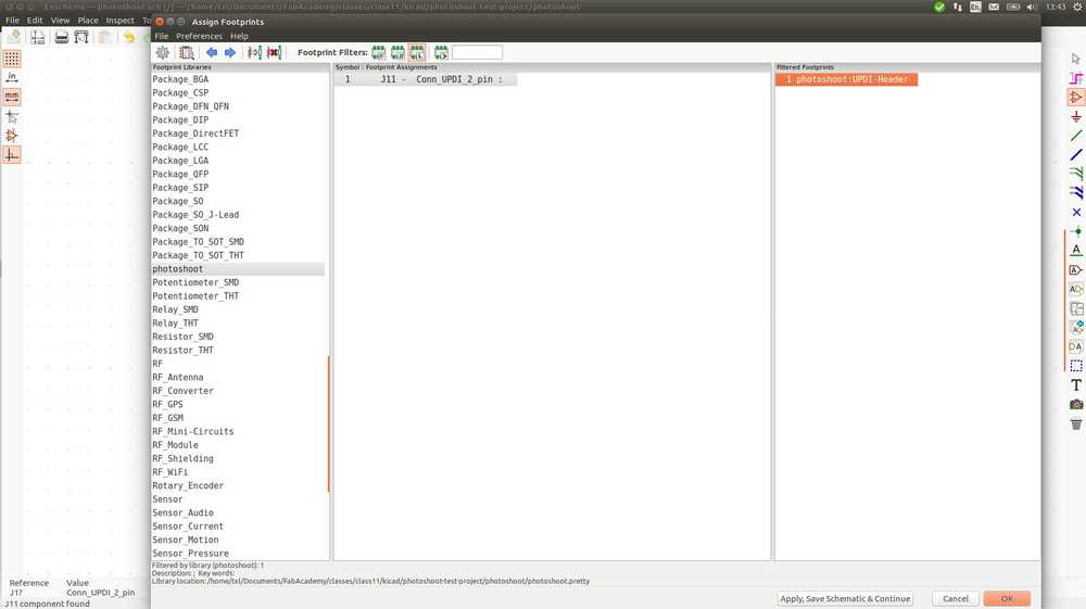
- select it, click
applyand then clickokto exit the window.
I also have to add header pins for the monitor. As described above it isn’t a straight header with four pads nicely in a row, but two ‘stepped’ rows. When looking through the footprint library to get inspiration for the new footprint above, I found the footprint for that component. Deb also mentions it: Connector_PinHeader_2.54mm:PinHeader_1x04_P2.54mm_Vertical_SMD_Pin1Right.
So I will make a new symbol and add that footprint to it.
Rectangle tool solution
I always have trouble drawing with the rectangle tool in KiCad. I draw a rectangle but it just disappears. Maybe I just found the solution. Select the tool, then click where you want to start, and then start drawing.
ATtiny 45
As described above I want to try both 4Kb IC and the 32Kb IC boards. Therefore I asked Henk to mill Neil’s board with the ATtiny45 for me on short notice while I design the board with the ATtiny3216. He was kind enough to want to do it. Here is the BOM for Neil’s board.
| Component | Quantity |
|---|---|
| ATtiny45 | 1 |
| ISP 6 pin header | 1 |
| FTDI 6 pin header | 1 |
| Capacitor with polarity 1uF | 1 |
| Resistor 10K | 3 |
| Conn_01x04_Male to OLED (SSD1306); use footprint Connector_PinHeader_2.54mm:PinHeader_1x04_P2.54mm_Vertical_SMD_Pin1Right | 1 |
Then Henk understood better what my plan was. And he let me know this isn’t very useful. He advised me to focus on the Arduino IDE because there isn’t much documentation on C-coding for the OLED. Thanks for the advise Henk and I will take it. In the unlikely event of spare time I can always simulate that the ATtiny3216 is a 4Kb ICU.
Schematic with ATtiny 3216-S
Wiring the components
I2C
- Reading up about the I2C protocol from i2c.info.
- ‘I2C is a serial protocol for two-wire interface to connect low-speed devices like microcontrollers, EEPROMs, A/D and D/A converters, I/O interfaces and other similar peripherals in embedded systems. It was invented by Philips and now it is used by almost all major IC manufacturers. Each I2C slave device needs an address – they must still be obtained from NXP (formerly Philips semiconductors).
- ‘I2C bus is popular because it is simple to use, there can be more than one master, only upper bus speed is defined and only two wires with pull-up resistors are needed to connect almost unlimited number of I2C devices. I2C can use even slower microcontrollers with general-purpose I/O pins since they only need to generate correct Start and Stop conditions in addition to functions for reading and writing a byte.
- ‘Each slave device has a unique address. Transfer from and to master device is serial and it is split into 8-bit packets. All these simple requirements make it very simple to implement I2C interface even with cheap microcontrollers that have no special I2C hardware controller. You only need 2 free I/O pins and few simple i2C routines to send and receive commands.
- I2C interface:
I2C uses only two wires: SCL (serial clock) and SDA (serial data). Both need to be pulled up with a resistor to +Vdd. There are also I2C level shifters which can be used to connect to two I2C buses with different voltages. 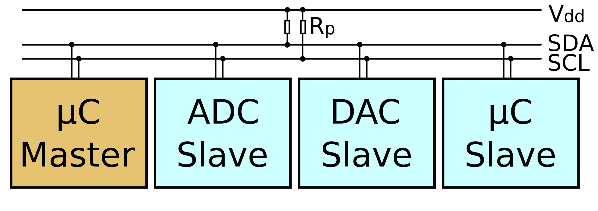
- I2C schema. Source Wikipedia. Accompanying text from Wikipedia: “An example schematic with one master (a microcontroller), three slave nodes (an ADC, a DAC, and a microcontroller), and pull-up resistors Rp”
-
I2C Addresses
Basic I2C communication is using transfers of 8 bits or bytes. Each I2C slave device has a 7-bit address that needs to be unique on the bus. Some devices have fixed I2C address while others have few address lines which determine lower bits of the I2C address. This makes it very easy to have all I2C devices on the bus with unique I2C address. There are also devices which have 10-bit address as allowed by the specification. -
7-bit address represents bits 7 to 1 while bit 0 is used to signal reading from or writing to the device. If bit 0 (in the address byte) is set to 1 then the master device will read from the slave I2C device. Master device needs no address since it generates the clock (via SCL) and addresses individual I2C slave devices.’

- Source: i2c.info
-
In normal state both lines (SCL and SDA) are high. The communication is initiated by the master device. It generates the Start condition (S) followed by the address of the slave device (B1). If the bit 0 of the address byte was set to 0 the master device will write to the slave device (B2). Otherwise, the next byte will be read from the slave device. Once all bytes are read or written (Bn) the master device generates Stop condition (P). This signals to other devices on the bus that the communication has ended and another device may use the bus.
SDA and SCL
So SDA and SCL are part of the I2C communication protocol. They each need a pull-up resitor connected to VCC. So in my Eeschema I need to connect resistors to the SDA and SCL and connect those to VCC.
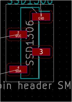
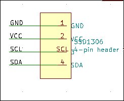
The OLED monitor has the pin-out printed on it:
GND – VCC – SCL – SDA
In Neil’s board the monitor pinhead is labeled VCC – GND – SCL – SDA. I wonder if I misunderstood something. But when I look at the video of his working monitor, I see that the pinout of his monitor is indeed different then mine: VCC – GND. So going with the monitor pinout is the correct way I think.
Pull-up resistors come in two kinds: external and internal. External means you add a physical resistor to the board. Internal pull-ups are controlled by software. Former FabAcademy student Yuichi Tamiya explains how the internal pull-up can be activated with the wire.h library. If you uncomment the line below the internal pullup will be activated. In that case an external pull-up may not be needed.
//pinMode(SDA,INPUT_PULLUP);//enable internal pullup:<Wire.h> already sets it enable
Here is the line to disable the internal pull-up.
//pinMode(SDA,INPUT);disable internal pullup:need this when external pullup resistor is used
Here is a discussion on the Arduino forum that discusses how to use the internal pull-up with the wire.h library.
Reset button
The reset button always needs a resitor and be connected to VCC.
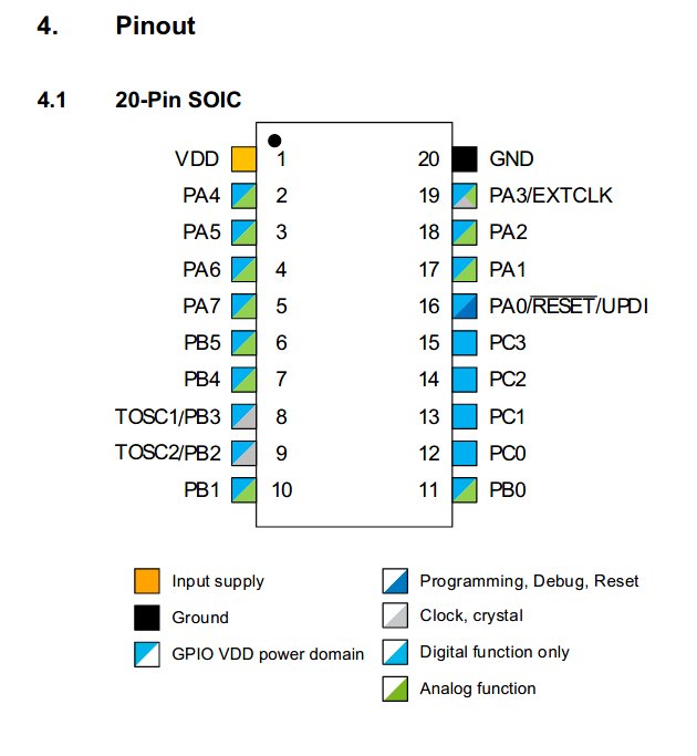
ATtiny3216 pinout
Using the ATtiny3216 Datasheet I am now going to find the pins I need. Looking at Neil’s board and Deb’s Eschema I figure I need the following pin functions:
| Pin function | Pin name | pin number |
|---|---|---|
| RST | PA0 | 16 |
| SDA | PB1 | 10 |
| SCL | PB0 | 11 |
| VCC | VCC | 1 |
| GND | GND | 20 |
| RX | PB3 | 8 |
| TX | PB2 | 9 |
| MISO | PA2 | 18 |
| MOSI | PA1 | 17 |
I notice that the RST pin and the UPDI pin are the same PA0. I’ll have to look into that. Later I find out that this is normal. With the UPDI you can do the reset with software.
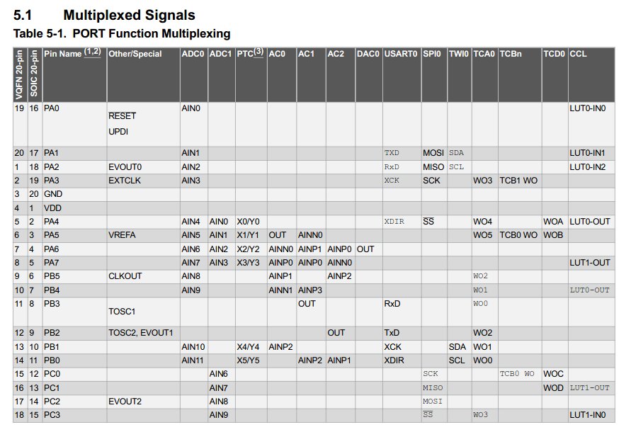
I notice that MISO MOSI and SCK are referenced twice. Once in PORT A and once under PCx. I am not sure what PCx is, I don’t think it is a third port C.
From the datasheet: ‘Tip: Signals on alternative pin locations are in typewriter font.’ So The MISO MOSI etc on PORT A are primary. I’ll go with those.
The table shows pin number for VQFN and for SOIC, I think these are two different ways of packaging the ICU. VQFN quad-flat no-leads is a cube like packaging. SOIC is Small Outline Integrated Circuit. I assume we will have the latter version because that one is in the FabInventory list. I check my Eschema and see that the footprint there is VQFN, so I adjust it. There are two types of AT3216 an -M and an -S version The difference? -M is VQFN, -S is SOIC. I’ll add that in the component table below.
The primary SDA and SCL are on PORTB1 & PORTB0. The secondary ones are on the same ports as the primary MISO and MOSI.
UART - RX TX
Henk keeps warning that people misalign their RX TX lines. I want to prevent that so I’m doing research. Couple of questions I try to answer:
- In the Eschema, you need to give trace ends the same name for them to be connected in the rats nest. So even if the FTDI RX should go to the ATtiny TX, the trace end names should still both be RX, right?
- Henk and others say: the receiving pin RX of one device (FTDI header) should go to the transmitting pin TX of the IC. That makes sense. A transmitted signal should go to the receiver. So should I hook up the RX pin of the FTDI to the TxD pin of the AT3216? I looked back at boards we made with ATtiny44. But its datasheet does not have a TxD pin function. Instead it has connects to AIN0.
The AT3216 has UART which the AT44 does not (I think). UART is about communication. But since we could communicate with AT44 as well, should I wire to the UART pin or another?
- I look up UART on wikipedia.
- ‘A universal asynchronous receiver-transmitter (UART) is a computer hardware device for asynchronous serial communication in which the data format and transmission speeds are configurable. The electric signaling levels and methods are handled by a driver circuit external to the UART. A UART is usually an individual (or part of an) integrated circuit (IC) used for serial communications over a computer or peripheral device serial port. One or more UART peripherals are commonly integrated in microcontroller chips. A related device, the universal synchronous and asynchronous receiver-transmitter (USART) also supports synchronous operation.
- ‘The universal asynchronous receiver-transmitter (UART) takes bytes of data and transmits the individual bits in a sequential fashion.[1] At the destination, a second UART re-assembles the bits into complete bytes. Each UART contains a shift register, which is the fundamental method of conversion between serial and parallel forms. Serial transmission of digital information (bits) through a single wire or other medium is less costly than parallel transmission through multiple wires.
- ‘Receiver
All operations of the UART hardware are controlled by an internal clock signal which runs at a multiple of the data rate, typically 8 or 16 times the bit rate. The receiver tests the state of the incoming signal on each clock pulse, looking for the beginning of the start bit. If the apparent start bit lasts at least one-half of the bit time, it is valid and signals the start of a new character. If not, it is considered a spurious pulse and is ignored. After waiting a further bit time, the state of the line is again sampled and the resulting level clocked into a shift register. - ‘Transmitter
Transmission operation is simpler as the timing does not have to be determined from the line state, nor is it bound to any fixed timing intervals. As soon as the sending system deposits a character in the shift register (after completion of the previous character), the UART generates a start bit, shifts the required number of data bits out to the line, generates and sends the parity bit (if used), and sends the stop bits.’
Asynchronous serial communication is what I came across when using the logical analyzer in week09.
The AT3216 has a USART (it can also do synchronous communication). It does not need an external clock.
- One-wire mode
- This (from the datasheet) may be something to pay attention to when programming:
- ‘When the USART is set in one-wire mode, the transmitter and the receiver share the same RxD I/O pin.When the USART is set in Master SPI mode, all USART-specific logic is disabled, leaving the transmit and receive buffers, Shift registers, and Baud Rate Generator enabled. Pin control and interruptgeneration are identical in both modes. The registers are used in both modes, but their functionalitydiffers for some control settings’
- There is a getting started with UART document. It says:
- ‘Note: The TX pin of the microcontroller must be connected to the RX pin of a UART to USB convertor. IfRX were also used, it has to be connected to the TX pin of a UART to USB convertor. Sometimes the devices have to share a common ground line also.’
So the RX of the FTDI must be connected to the TX of the AT3216. check.
But do I need to use the UART pin (PB2)? Or should I use one of the AINN0 pins like in the ATtiny44 boards we’ve made before?
On this forum they ask: why on earth connect FTDI to UART?
In the Fab Archive Mohammed explains the RX TX enigma. He writes: ‘So you connect the board pin you assigned (Tx) to the pre-assigned pin of the FTDI (Rx).’
Here is what I think, the AT3216 is a powerful microcontroller. It likely has multiple pins that can serve as TX. ATtiny44 can do TX communication without UART. So I will use a ‘normal’ pin and not a UART pin for TX.
Here is a board Neil made with the AT3216. This may also come in handy with the UPDI later.
Here is an interesting write-up about UART to FTDI communication.
- And FTDI (the company) itself on FTDI UART communication
- ‘The USB TTL Serial cables are a range of USB to serial converter cables which provide connectivity between USB and serial UART interfaces. A range of cables are available offering connectivity at 5V, 3.3V or user specified signal levels with various connector interfaces.
- All cables feature an FTDI FT232R device integrated within the cable USB type ‘A’ connector, which provide access to UART Transmit (Tx), Receive (Rx), RTS#, CTS#, VCC (5V) and GND connections. All cables are fully RoHS compliant and are FCC/CE approved.’
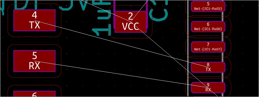
Okay, final decision I will connect the FTDI to the UART pins. And I am adding a TX trace next to the RX from the examples.
So the FTDI’s RX has to go to the AT3216’s TX = PB2. FTDI TX goes to AT RX = PB3. To avoid confusion, rather then using labels in the schematic to connect the pins, I’ll use visible lines. Otherwise the IC’s TX pin has to be labeled RX in order to rightly connect to the FTDI’s RX pin
Capacitor
Questions:
- polarized or unpolarized?
- If polarized, which part to GND and which part to VCC?
- Which value? 1uF?
Sparkfun says: capacitors of 1uF and less are nor polarized.
For now I am going to use a unpolarized capacitor.
Value: In the AT3216 Hello Echo board of Neil the capacitor is 1uF and also in the OLED example boards.
Looking up what capacitor values to use there is a lot of math with variables I do not know about my circuit (what is the cutoff frequency!!?1!??). I leave it at 1uF for now.
UPDI pin
So the UPDI pin in the datasheet is the same as the reset pin. No reset pin needed with UPDI? And can I then also loose the accompanying resistor? In the AT3216 Hello Echo board of Neil there is no Reset button and no resistor.
From a datasheet ‘UPDI uses the Reset line to detect the debugger probe.’ So it is supposed to be on the Reset pin.
Ieks! ‘Single-wire interface can be enabled by setting a fuse or by 12V programming, which disables the reset functionality. Not all programming tools are capable of generating this voltage. Note: Refer to the respective programmer user guide for more information about the capabilities and physical interface of UPDI.’ I am not going to use 12V, hope that won’t be a problem.
- More on that from the AT3216 datasheet:
- ‘Programming and debugging are done through the UPDI Physical interface (UPDI PHY), which is a 1-wire UART-based half duplex interface using the RESET pin for data reception and transmission. Clocking of UPDI PHY is done by an internal oscillator. Enabling of the 1-wire interface, by disabling theReset functionality, is either done by 12V programming or by fusing the RESET pin to UPDI by setting the RESET Pin Configuration (RSTPINCFG) bits in FUSE.SYSCFG0. The UPDI access layer grants access to the bus matrix, with memory mapped access to system blocks such as memories, NVM, and peripherals’
Lots of stuff to worry about ahead. I am going for Wiring the UPDI to the reset pin and GND and hope for the best.
Oh, which one should be GND & which data? I looked up the UPDI board from previous weeks and checked the GND DATA layout.
With the Reset button gone, I remove the third resistor from my schematic.
With that it is all done with a lot of known unknowns.
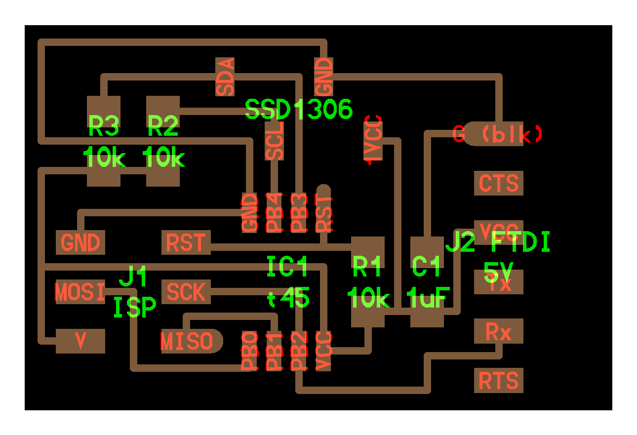
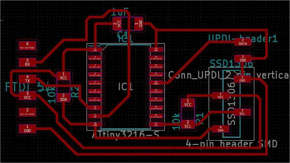
Final schematic:
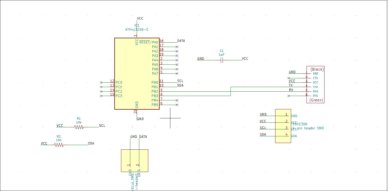
Footprints, ERC, Netlist
I follow the steps from week06 to add footprints. I have to add the new library I made with the UPDI footprint: In the footprint editor click preference > manage footprint libraries. Add the <name>.mod file.
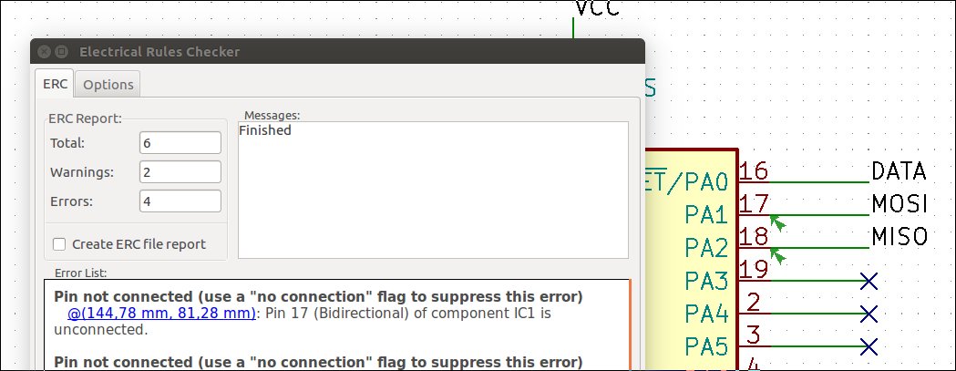
I run the Electrical Rules Check. And the MISO and MOSI wires are marked as not connected. I added these because they are needed for the ISP programmer but now that I am using UPDI they are no longer necessary. So I remove them.
A second type of error the ERC detects is that a ‘Different net assigned to a shared pin in another unit of the same component’.
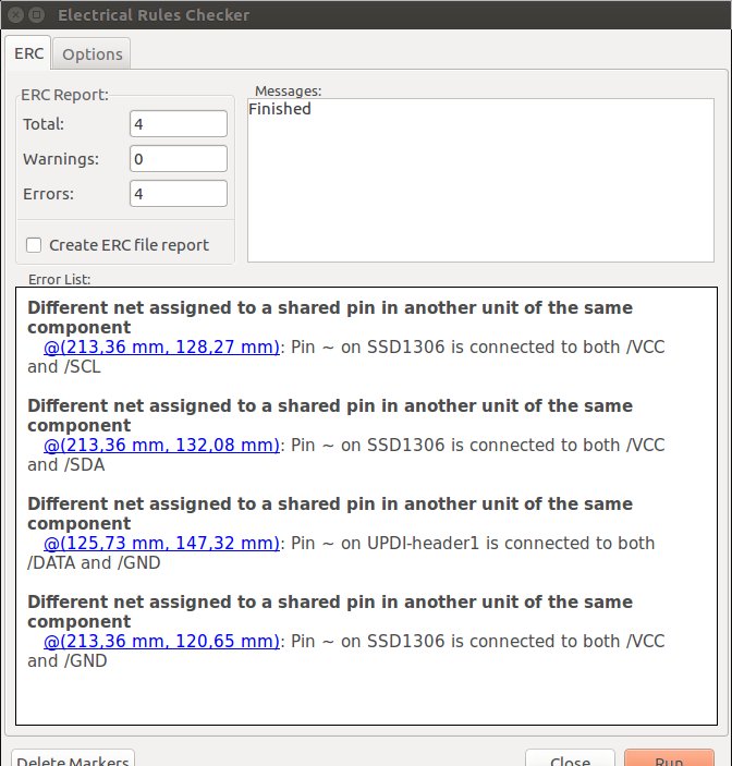
Hitting the internetz… On this forum they mention it could be something with the symbols. Since it is happening to both the symbols I made myself, this is probably where the problem lies. But what is the problem and, more importantly, how to fix it?
KiCad forum says that it could be having the same pin numbers assigned. In the symbol editor (KiCad main workbench, second icon in the top row) select the symbol by clicking on it, then click pin table icon  .
.
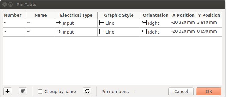
So my pins aren’t numbered. Perhaps KiCad sees that as a problem. When you click on the pin specifically (so not just anywhere on the symbol) you can adjust pin name and pin number fields.
When I name and number the pins of the two symbols, the ERC errors go away.
PCB new
I go to the PCB new workbench. Import the Netlist. Set the Bord Setup Design Rules.
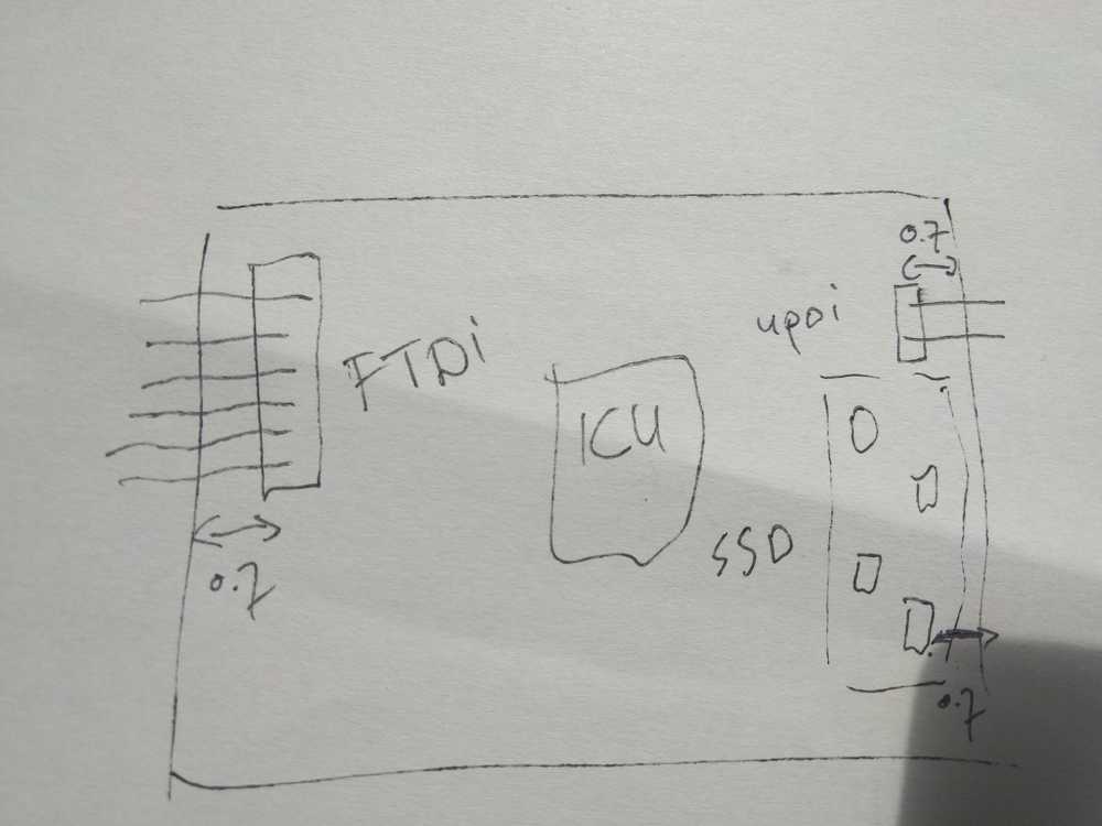
The board layout: There are three connector pins: UPDI, FTDI & the SSD1306. Both UPDI & FTDI need to be on the edge of the board in order to connect to the cables. From previous board I know that the connector needs to be about 0.7 mm from the edge of the board to make a good connection. (To much space between edge and connector makes it impossible to slide the connector in.)
I notice there is not wire going from the SDA pad on the SSD1306 pinhead to the rest of the board.
Back to the Eeschema.
Looks like I reversed pin name and number. I adjust in the symbol editor. Save Eschema. Click the Update PCB from Schematic icon.
Fixed.
The I notice the TX from the FTDI is wired to the TX from the ICU. Even though I wired TX - RX in the schemtic.
No, the wiring is still correct. PCBnew has just named the pins on the IC after the wire. Should I correct that? Hmm, it has given all the IC pins new generic names, rather then the ones from the schematic (PA1 is now named NET-IC1-Pad19 etc.). It has probably something to do with me adding my own pin names. I am going to leave it as is. It does not matter for the actual traces on the board. Although it is confusing as a reference document now.
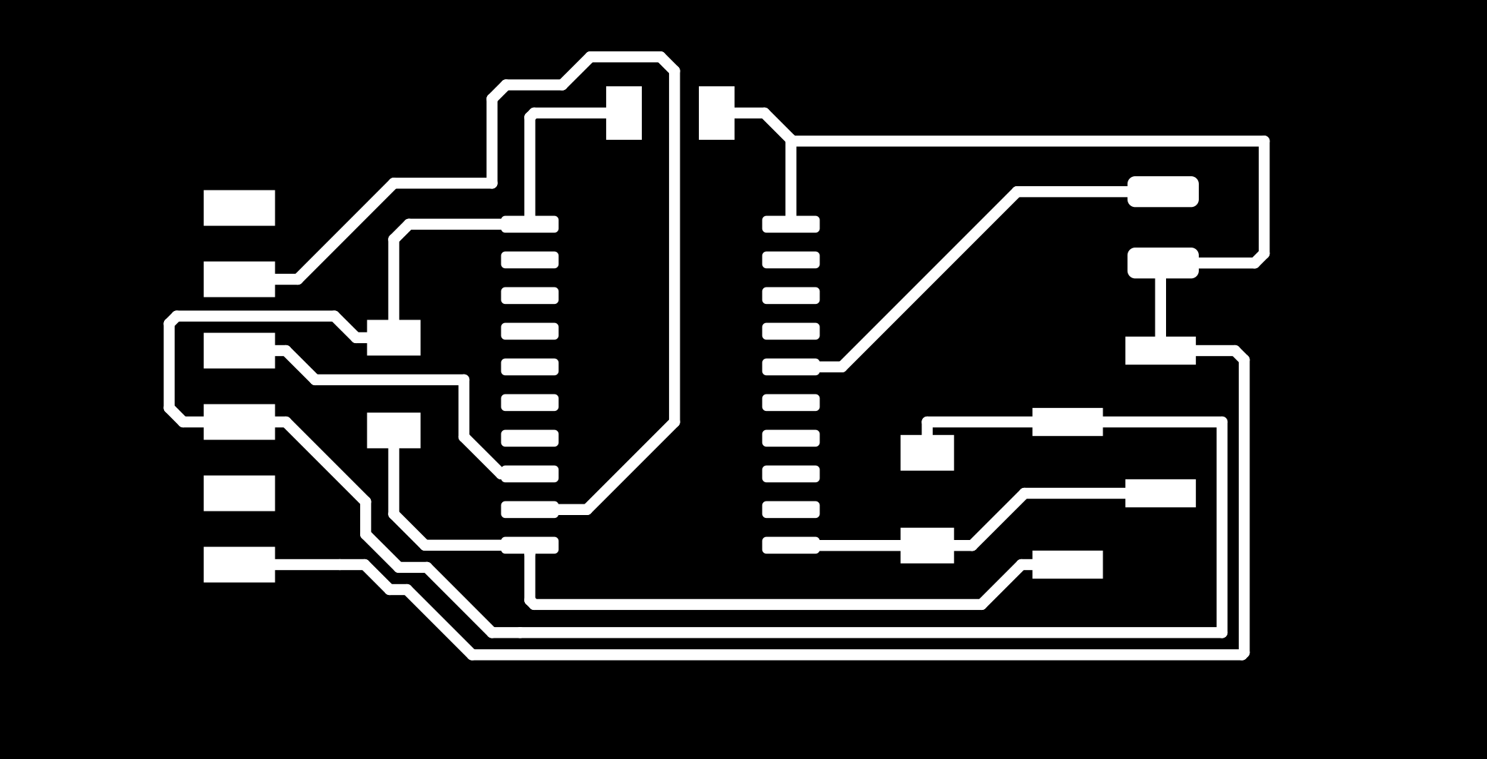
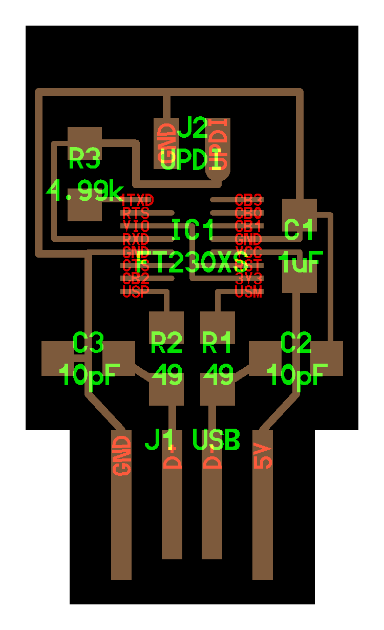
After routing and cleaning up the board I realized I had not considered the orientation of the headers. The UPDI was the wrong way around. And the FTDI as well. Rerouted the board and this is my final board.
Drew an outline. Forgot to set the layer manager to edge cuts. Got an empty .SVG edge cut when I exported. Did it again.
In Gimp removed alpha channel, inverted and exported as PNG.
I tested the design in mods at http://mods.cba.mit.edu/ and it looked like it would be milled properly. Henk will mill the board at the lab.
Component table
| Component | Quantity | Orientation |
|---|---|---|
| ATtiny3216-S | 1 | Yes |
| FTDI 6 pin header | 1 | yes |
| 2 pin UPDI header | 1 | no |
| Capacitor unpolarized 1uF | 1 | |
| Resistor 10K | 2 | no |
| Conn_01x04_Male to OLED (SSD1306); use footprint Connector_PinHeader_2.54mm:PinHeader_1x04_P2.54mm_Vertical_SMD_Pin1Right | 1 | yes (because of footprint) |
| USB cable to connect both FTDI & UPDI | 2 |
Debugging table
As I am drawing my board there are many things I am uncertain about. I will note them here. If the board does not work, I can use it as a debugging table
| Component | Uncertainty |
|---|---|
| TX RX | TX RX <> RX TX wired correctly? |
| TX RX | I used the UART pins for TX/RX communication, should I have used other pins? |
| Capacitor | I used unpolarized capacitor |
| Capacitor | Did I use the right value (1uF)? |
| UPDI | No reset pin? And therefore no resistor? |
| UPDI | correct footprint? |
| TX | I added a TX wire from FTDI to IC, this is not in the example designs. |
| Wiring | for much wiring I am not entirely sure (TX RX). Remember: you can always use cables to connect pins to different pins. |
| Resistors | Do I have enough resistos . I removed because there is no reset button. |
| UPDI | set fuses to enable it? |
| Monitor wants 3.3 V | How do I regulate that? |
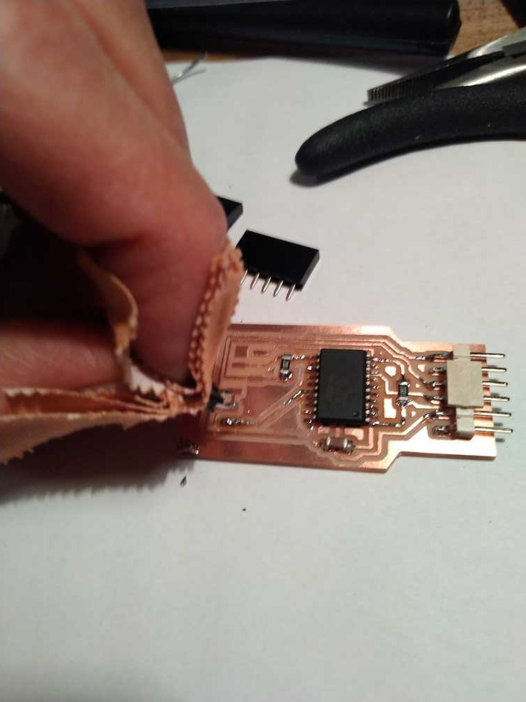
Soldering
The soldering of the IC went much better than the first time I soldered such a tiny component. This time the challenge was the pins for the UPDI. We didn’t have the exact component in the lab so I had to adjust an existing component. It was Henk’s idea. We had a straight pin and I had to bend them into of a kind of 30 degree bended pin.
The connector for the monitor also needed adjustment. Bending two of the four pins 180 degrees to create the ‘stepped’ layout. Yes, the stepped footprint I so painstakingly made in KiCad. haha.
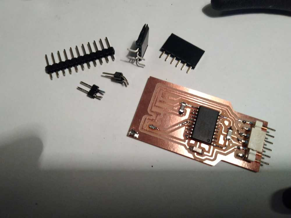
Bending the monitor connector’s pins was more easy then I thought. I’d thought they’d easily break but they didn’t.
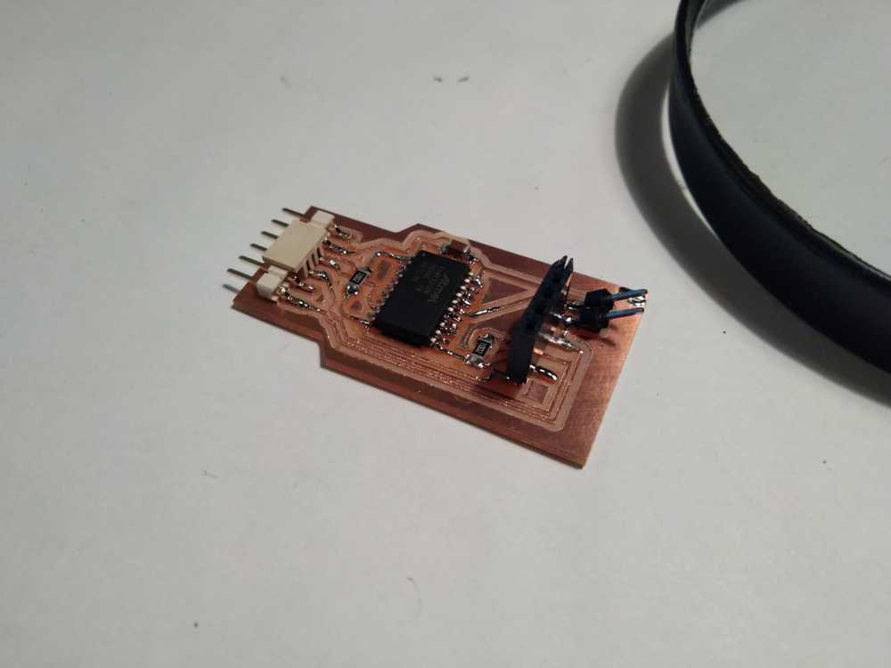
The UPDI connector was being a bother. Bending the pins went semi okay but it wouldn’t be caught by the solder. I was holding the connector while melting the solder. It just would not stick but it would get really hot. In the end I stuck three layers of band aid on fingers and then I could hold it long enough to get caught by the solder.
Here is the result.
Programming Schrödinger’s bordje
I dub this board Schrödinger bordje. There were so many unknowns in the making of the board that I have no idea if it will work. At this moment, the board may work or it may not work. Once I plug it in it might turn out the cat is dead.
I haven’t programmed with a UPDI yet so I have to figure that out first. Henk later explained more about the UPDI to me. I thought it was the same as the ISP we made in week04. A programmer that you first need to program itself, after which it is a dedicated device for programming AVR devices.
But the UPDI is a little different. The chip on the board is an integrated circuit. It already has the programming capabilities once the board is finished. Therefore you do not need to program the UPDI board itself.
Another important point is that the UPDI, unlike the ISP, can’t provide electricity to the to-be-programmed board. Therefore you need to connect the board both to the UPDI and the FTDI. The FTDI will be providing the current.
In the global review the UPDI also came up: UPDI is a protocol to program a class of chips made by Microchip. FTDI is a device/cable that has USB communicate to serial.
Preparing the development environment
To prepare the development environment you need to do two things:
1. Add the AT3216 board to the Arduino IDE
2. Install the UPDI development software.
3. Install Python serial monitor
1. Arduino IDE
Hyejin’s page was a lot of help in the following steps.
First add the AT3216 board to the Arduino IDE:
File > Preferences and add this url (http://drazzy.com/package_drazzy.com_index.json) to the Additional Board Manager URLs field.
Under Tools > Board > Boards Manager I search for and installed megatinycore.
Find out the Port the UPDI is connected to with dmesg. Outputs: FTDI USB Serial Device converter now attached to ttyUSB0.
Or use python -m serial.tools.list_ports. Dmesg only seems to show the FTDI port, not UPDI. Output of the Python command:
/dev/ttyUSB0
/dev/ttyUSB1
2 ports found
Select the port in the Arduino IDE under Tools.
Select the Programmer jtag2UPDI MegaTinyCore
I then connected the UPDI to the USB cable, cable to computer and Schrödinger’s bordje to the UPDI. (In retrospect this might have been a mistake. The FTDI should also be connected to power the board. )
Based on Neil’s Hello Echo 3216 video example I set the settings in the Arduino IDE under tools.
Settings in the Arduino IDE:
- Board: ATtiny3216 (not ATtiny3216 optiboot)
- Chip ATtiny3216
- BOD voltage 1.8V
- BOD mode Active ‘disabled’
- BOD mode Sleep ‘disabled’
- EEPROM retained
- Clock speed 20MHz
- millisec enabled default timer
- Voltage for UART closer to 5V
- Port /dev/ttyUSB0
- Programmer jtag2updi (megatinycore)
In Neil’s example you can also set the UART TX RX pins, the I2C pins and the SPI pins. I don’t have these options but this will turn out not to be a problem.
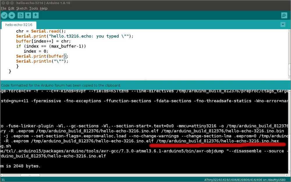
Next you can use Neil’s Hello Echo code for the 3216. Paste this in an Arduino sketch. Click the verify button. This will creates a number of files including a .hex file in the directory: /tmp/arduino_build_812376/.
In the ISP programmer environment, you create a .hex file with the Make program and then install it with Make and AVRdude. But UPDI works different. The .hex is created by the Arduino IDE but the installation in done with the UPDI programming software.
2. UPDI programming software
The UPDI programming software is called pyupdi. This program is used to program with UPDI.
Pip is an installer used to install Python based programs. We already installed Pip in week01, because you need it for Git and Mkdocs. Pip tutorial
To install pyupdi run: pip install https://github.com/mraardvark/pyupdi/archive/master.zip
Error I received an error:
WARNING: Building wheel for wrapt failed: [Errno 13] Permission denied: '/home/txl/.cache/pip/wheels/df'

Successfully built pyupdi
Failed to build wrapt
Installing collected packages: intelhex, mccabe, isort, six, lazy-object-proxy, typed-ast, wrapt, astroid, pylint, pyserial, pyupdi
    Running setup.py install for wrapt ... done
Successfully installed astroid-2.3.3 intelhex-2.2.1 isort-4.3.21 lazy-object-proxy-1.4.3 mccabe-0.6.1 pylint-2.4.4 pyserial-3.4 pyupdi-0.0.0 six-1.14.0 typed-ast-1.4.1 wrapt-1.11.2
(This is a similar warning as the one I got last week. Git/mkdocs would not work anymore. It affected many Fab students and there was a fix shared globally. That error message also said something about ‘wheel’. (That error message is documented in week01 in the Git paragraph.))
Because error warning said something about ‘permission denied’ I tried again using sudo.
sudo pip install https://github.com/mraardvark/pyupdi/archive/master.zip
But a similar warning:
WARNING: The directory '/home/txl/.cache/pip' or its parent directory is not owned or is not writable by the current user. The cache has been disabled. Check the permissions and owner of that directory. If executing pip with sudo, you may want sudo's -H flag.
However, this time it was able to build the wheel:
Building wheels for collected packages: pyupdi
  Building wheel for pyupdi (setup.py) ... done
  Created wheel for pyupdi: filename=pyupdi-0.0.0-py3-none-any.whl size=14580
I check the Ubuntu forum about the permissions: ‘Looks like the permissions in your ~/ are messed up. All files there should be owned by you. Use find ~/ -user root to see if root has taken over some of it, especially the directory’s in the error you posted. Change permissions back to yourself where necessary.’
I run: find ~/ -user
Output: /home/txl/.cache/pip/wheels/84
run: sudo chown -R txl:txl /home/txl/.cache/pip/wheels to change permissions.
But I still get: Defaulting to user installation because normal site-packages is not writeable
Besides pyupdi you also have to install some additional packages. Note that instead of Pip the installer is now named Pip3. Pip3 is used for installing Python programs of version 3. Pip is used for Python v2.
Run: pip3 install intelhex pylint pyserial
output: Defaulting to user installation because normal site-packages is not writeable.
For the rest it said: Requirement already satisfied: and named all the packages. So the packages are installed.
Using pyupdi
The next step to program the 3216board with the UPDI is to call on the pyupdi and tell it to program a hex file on the 3216.
The general command is:
python3 pyupdi.py -d your_processor -c your_port -b your_baud_rate -f your_hex -v.
I adjusted the variables: your_processor = attiny3216.
Your_port is found with dmesg ttyUSB0 in my case.
Your_hex: when you run the code in the Arduino IDE by clicking verify, there is output in the panel below. Here you can find the name of the .hex file.
You can also configure the Arduino IDE to output the .hex file in a specified folder. Fab student Tamiya has provided a step-by-step explanation on how to configure the Arduino IDE to do so.
After adjusting the variables the command looks like this:
python3 pyupdi.py -d ATtiny3216 -c ttyUSB0 -b -f /tmp/arduino_build_812376/hello-echo-3216.ino.hex -v
Output:
python3: can't open file 'pyupdi.py': [Errno 2] No such file or directory
I do pip install --upgrade setuptools
I realize i forgot to cd into the proper directory. To find out in which directory pyupdi is installed I run: txl@T460:/$ whereis pyupdi.py
Output: pyupdi: /home/txl/.local/bin/pyupdi.py
So I cd .local/bin/
Now pyupdi works:
From the directory txl@T460:~/.local/bin$ I run the command python3 pyupdi.py -d ATtiny3216 -c ttyUSB0 -b -f /tmp/arduino_build_812376/hello-echo-3216.ino.hex -v
python3 pyupdi.py -d ATtiny3216 -c ttyUSB0 -b  -f /tmp/arduino_build_812376/hello-echo-3216.ino.hex -v
usage: pyupdi.py [-h] -d
                 {avr128da28,avr128da32,avr128da48,avr128da64,mega3208,mega3209,mega4808,mega4809,tiny1604,tiny1606,tiny1607,tiny1614,tiny1616,tiny1617,tiny202,tiny204,tiny212,tiny214,tiny3216,tiny3217,tiny402,tiny404,tiny406,tiny412,tiny414,tiny416,tiny417,tiny804,tiny806,tiny807,tiny814,tiny816,tiny817}
                 -c COMPORT [-e] [-b BAUDRATE] [-f FLASH] [-r] [-i]
                 [-fs [FUSES [FUSES ...]]] [-fr] [-v]
pyupdi.py: error: argument -d/--device: invalid choice: 'ATtiny3216' (choose from 'avr128da28', 'avr128da32', 'avr128da48', 'avr128da64', 'mega3208', 'mega3209', 'mega4808', 'mega4809', 'tiny1604', 'tiny1606', 'tiny1607', 'tiny1614', 'tiny1616', 'tiny1617', 'tiny202', 'tiny204', 'tiny212', 'tiny214', 'tiny3216', 'tiny3217', 'tiny402', 'tiny404', 'tiny406', 'tiny412', 'tiny414', 'tiny416', 'tiny417', 'tiny804', 'tiny806', 'tiny807', 'tiny814', 'tiny816', 'tiny817')
The console tells me I used the wrong name for the processor. I change it to tiny3216. And run: python3 pyupdi.py -d tiny3216 -c ttyUSB0 -b -f /tmp/arduino_build_812376/hello-echo-3216.ino.hex -v
Output warns me I forget to set the baudrate. Hyejin uses 57600 for tiny1614 so I’ll use that.
python3 pyupdi.py -d tiny3216 -c ttyUSB0 -b 57600 -f /tmp/arduino_build_812376/hello-echo-3216.ino.hex -v
Still no dice:
"could not open port {}: {}".format(self._port, msg))
serial.serialutil.SerialException: [Errno 2] could not open port ttyUSB0: [Errno 2] No such file or directory: 'ttyUSB0'
I run python -m serial.tools.list_ports
output:
/dev/ttyUSB0
/dev/ttyUSB1
2 ports found
I run both ports but nothing.
Henk then reveals to me my third and final error in this command: It’s /dev/ttyUSB0, not ttyUSB0.
python3 pyupdi.py -d tiny3216 -c /dev/ttyUSB1 -b 57600 -f /tmp/arduino_build_812376/hello-echo-3216.ino.hex -v
I don’t really like making this last mistake because I also made it in week09. I do hope I am learning something from my mistakes, grrr.
(Added later on June 22, 2020. The python -m serial.tools.list_ports command is not the best way to find ports. It will just output two ports. In order to find which port is hosting which device, you need to unplug one device, run the command and see which port is still being occupied. This is a bit crude. Yuichi Tamiya offers a more elegant way to pinpoint which device is using which port. This is done by listing the serial numbers of the devices at the ports.)
Now that I have the command right, the computer sees the device. But I get an error:
INFO:link UPDI not OK - reinitialisation required
Traceback (most recent call last):
  File "pyupdi.py", line 182, in <module>
    _main()
  File "pyupdi.py", line 97, in _main
    device=Device(args.device))
  File "/home/txl/.local/lib/python3.5/site-packages/updi/nvm.py", line 17, in __init__
    self.application = UpdiApplication(comport, baud, device)
  File "/home/txl/.local/lib/python3.5/site-packages/updi/application.py", line 17, in __init__
    self.datalink = UpdiDatalink(comport, baud)
  File "/home/txl/.local/lib/python3.5/site-packages/updi/link.py", line 32, in __init__
    raise Exception("UPDI initialisation failed")
Exception: UPDI initialisation failed
INFO:phy Closing port '/dev/ttyUSB1'
On advice of Henk I test with the multimeter:
First I test if the current runs properly over the traces. I put the multimeter on the OHM setting. The meter provides its own power. Place the probes at a connected trace. If current runs it will give a sound. All traces seem to work as they should.
Then I test if the board receives power. As Henk explained, the power must come from the FTDI board. Testing with the multimeter.
Place the setting on Direct Current (gelijkstroom), the symbol is a straight line with a dotted line underneath it. Henk said to put the setting at 20.
I tested but there was no voltage. Then Henk tested, saw that the FTDI was the wrong way around in the USB cable. He turned it around and then there was 5V everywhere.
Another rookie mistake I have made before :/
So, again: the UPDI board is connected to the computer by USB cable, UPDI board is connected to my 3216 board. That in turn is connected to the FTDI board. Which is connected via USB to the computer.
Again I run:
python3 pyupdi.py -d tiny3216 -c /dev/ttyUSB1 -b 57600 -f /tmp/arduino_build_812376/hello-echo-3216.ino.hex -v
Now the board was recognized. Data was being transmitted but not succesfully. Error message:
Traceback (most recent call last):
  File "pyupdi.py", line 102, in _main
    nvm.enter_progmode()
  File "/home/txl/.local/lib/python3.5/site-packages/updi/nvm.py", line 34, in enter_progmode
    if self.application.enter_progmode():
  File "/home/txl/.local/lib/python3.5/site-packages/updi/application.py", line 158, in enter_progmode
    sys_status = self.datalink.ldcs(constants.UPDI_ASI_SYS_STATUS)
  File "/home/txl/.local/lib/python3.5/site-packages/updi/link.py", line 60, in ldcs
    self.updi_phy.send([constants.UPDI_PHY_SYNC, constants.UPDI_LDCS | (address & 0x0F)])
  File "/home/txl/.local/lib/python3.5/site-packages/updi/physical.py", line 81, in send
    echo = self.ser.read(len(command))
  File "/home/txl/.local/lib/python3.5/site-packages/serial/serialposix.py", line 483, in read
    ready, _, _ = select.select([self.fd, self.pipe_abort_read_r], [], [], timeout.time_left())
KeyboardInterrupt

During handling of the above exception, another exception occurred:

Traceback (most recent call last):
  File "pyupdi.py", line 182, in <module>
    _main()
  File "pyupdi.py", line 105, in _main
    nvm.unlock_device()
  File "/home/txl/.local/lib/python3.5/site-packages/updi/nvm.py", line 54, in unlock_device
    self.application.unlock()
  File "/home/txl/.local/lib/python3.5/site-packages/updi/application.py", line 108, in unlock
    raise Exception("Key not accepted")
Exception: Key not accepted
I opened the Arduino IDE and ran the verify button again to make a new .hex file. I replaced the hex file name in the command with the newly created hex file:
python3 pyupdi.py -d tiny3216 -c /dev/ttyUSB1 -b 57600 -f /tmp/arduino_build_961445/hello-echo-3216.ino.hex -v
Succes! The UPDI had succesfully programmed the 3216 board.
3. Python serial monitor
To test if the code works, I needed to use the Python serial monitor. It displays serial communication between your computer and a serial device. It was discussed in the embedded programming week and that is where I find the following command: python -m serial.tools.miniterm /dev/your_device_port your_baud_rate
To find the port: python3 -m serial.tools.list_ports
FTDI is on /dev/ttyUSB0. I replace ‘your_device’ by /dev/ttyUSB0.
This error is because I had both the Arduino serial monitor open and the Python serial monitor.
Exception in thread rx:
Traceback (most recent call last):
  File "/usr/lib/python2.7/threading.py", line 801, in __bootstrap_inner
    self.run()
  File "/usr/lib/python2.7/threading.py", line 754, in run
    self.__target(*self.__args, **self.__kwargs)
  File "/usr/lib/python2.7/dist-packages/serial/tools/miniterm.py", line 403, in reader
    data = self.serial.read(self.serial.in_waiting or 1)
  File "/usr/lib/python2.7/dist-packages/serial/serialposix.py", line 495, in read
    raise SerialException('device reports readiness to read but returned no data (device disconnected or multiple access on port?)')
SerialException: device reports readiness to read but returned no data (device disconnected or multiple access on port?)
For baudrate I first use the baud rate that I also used in the UPDI command: 57600. But this resulted in weird characters being outputted in the monitor.
I then copy the baudrate that Hyejin used: 115200.
python3 -m serial.tools.miniterm /dev/ttyUSB0 115200
(Hyejin also added a command for debugging. When you add this, the monitor will output information for debugging: python3 -m serial.tools.miniterm -f debug /dev/ttyUSB0 115200. This may come in handy one day.)
And then it works:
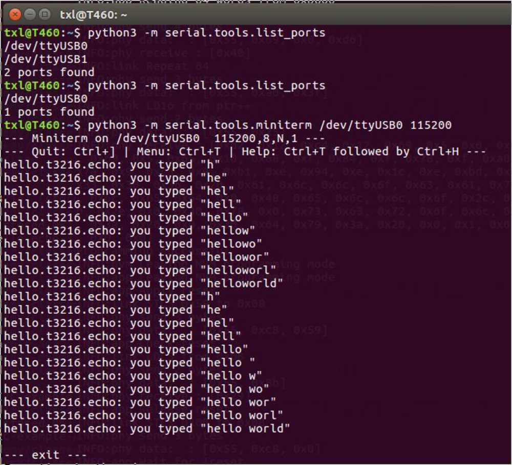
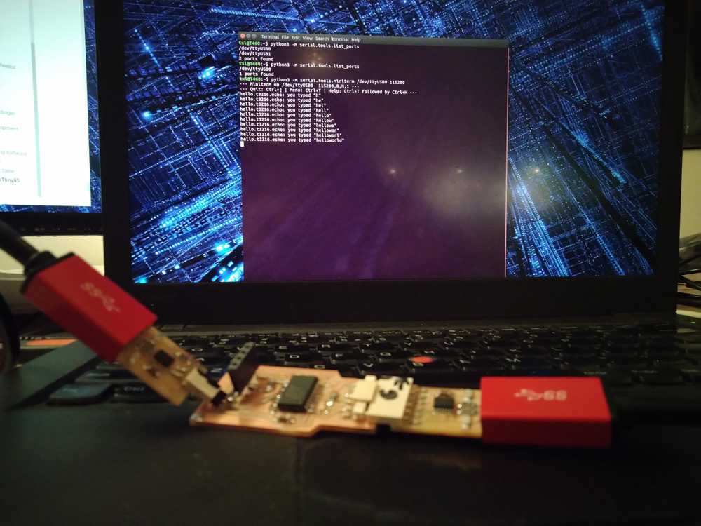
Schrödinger’s bordje is alive!
OLED monitor software
And now that I know that the board is alive, I have to load the monitor software on it.
So I have to fill up the variables of the command:
python3 pyupdi.py -d tiny3216 -c /dev/ttyUSB1 -b 57600 -f /tmp/arduino_build_961445/hello-echo-3216.ino.hex -v
your_processor = /dev/ttyUSB0 (with: python3 -m serial.tools.list_ports)
your_baudrate = 9600 (from the Adafruit code)
your_hex = /tmp/arduino_build_169481/I2C-example-Ada.ino.hex (From the Arduino panel)
In the Adafruit code one pin is defined:
#define OLED_RESET 4 // Reset pin # (or -1 if sharing Arduino reset pin)
I wondered what to set it to. Found on a forum that you can reset the OLED in software. That means you don’t havre to assign a pin. In that case set the pin to -1.
So I end up with:
python3 pyupdi.py -d tiny3216 -c /dev/ttyUSB0 -b 9600 -f /tmp/arduino_build_169481/I2C-example-Ada.ino.hex -v
Errorzzz
UnicodeDecodeError: 'utf-8' codec can't decode byte 0xb1 in position 0: invalid start byte
INFO:phy Closing port '/dev/ttyUSB0'
I suspect it’s the baudrate and change it to: 57600
Same error. But I realize I used the wrong USB port. Checking for the FTDI instead of the UPDI. So I change it to USB1
python3 pyupdi.py -d tiny3216 -c /dev/ttyUSB1 -b 57600 -f /tmp/arduino_build_169481/I2C-example-Ada.ino.hex -v
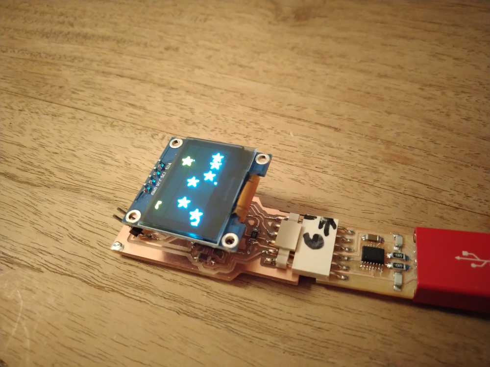
Output: Programming successful :)
I plug in the monitor. Unplug the FTDI (voltage) and plug it back in and on come the Adafruit stars on the monitor. :)
Overview programming with UPDI
Arduino IDE
Settings in the Arduino IDE:
- Board: ATtiny3216 (not ATtiny3216 optiboot)
- Chip ATtiny3216
- BOD voltage 1.8V
- BOD mode Active ‘disabled’
- BOD mode Sleep ‘disabled’
- EEPROM retained
- Clock speed 20MHz
- millisec enabled default timer
- Voltage for UART closer to 5V
- Port /dev/ttyUSB*
- Programmer jtag2updi (megatinycore)
Find port:
python -m serial.tools.list_ports
pyupdi
-
cd into
pyupdidirectory. To find where it is installedtxl@T460:/$ whereis pyupdi.py. Output:/home/txl/.local/bin/pyupdi.py -
To program the board the general command is:
python3 pyupdi.py -d your_processor -c your_port -b your_baud_rate -f your_hex -v.
Finding the variables:
Your_processor: tiny3216
Find port: python -m serial.tools.list_ports or dmesg. Output is /dev/ttyUSB* (remember to add the /dev/...)
Find baud rate: copied from others: 57600
Find hex file: Is created by the Arduino IDE and is printed in the compile panel. For instance: /tmp/arduino_build_163214/I2C-example-Ada.ino.hex
General debugging table
| Look at | check |
|---|---|
| Check your wires, are the USBs placed correctly | |
| Are connectors properly placed GND on GND | |
| Have you cd’d into the right directory | |
| Dmesg gives the port but when it is a device add: /dev/ as in /dev/ttyUSB0 |
OLED board with ATtiny85
After I found out that there is also smaller code packages for running the OLED, I also looked into making an OLED board with the ATtiny85. But I did not finish this project for lack of time.
But you can use the Tiny4kOLED library in combination with the TinyWireM.h library. I got this to work on the Arduino.
I started some research on making the ATtiny85 board. But did not finish the board. Here is the preliminary research:
There are multiple ATtiny85’s. The difference is in the packaging and speed. I choose the ATtiny85-20SU which has SOIC packaging and 20MHz speed (instead of 10MHz like the ATtiny85V-10SU). For the rest of the components I looked at NEil’s ATtiny45 OLED board.
The pinout that Neil uses does not comply with the pinout described in the datasheet.
Here is a tutorial
| Component | Quantity | Orientation |
|---|---|---|
| ATtiny85-20SU | 1 | Yes |
| FTDI 6 pin header | 1 | yes |
| Capacitor with polarity 1uF | 1 | |
| Resistor 10K | 2 | no |
| Conn_01x04_Male to OLED (SSD1306); use footprint Connector_PinHeader_2.54mm:PinHeader_1x04_P2.54mm_Vertical_SMD_Pin1Right | 1 | yes (because of footprint) |
| USB cable to connect both FTDI & UPDI | 2 |
Global lecture
Output: getting signals out of the electronics.
Blue LED needs more current so less resistor 499 instead of 1000.
Rastering LED’s to make a display. Charlieplexing.
LCD don’t use it. Make it i2c. There are standard libraries. Large library you need much memeort tiny1614
OLED: bitmap display. Use SPI or I2C. Software implementation of I2C. You can also do graphs because it is bitmap.
Mosfet. Two kinds of mosfet
Some notes without context
Oled for Arduino https://www.instructables.com/id/Monochrome-096-i2c-OLED-display-with-arduino-SSD13/
http://fab.cba.mit.edu/classes/863.19/CBA/people/Daniel/static/week9.html
https://www.arduino.cc/en/Tutorial/ReadAnalogVoltage
http://fab.cba.mit.edu/classes/863.19/CBA/people/zach/final.html
https://github.com/SpenceKonde/megaTinyCore/blob/master/MakeUPDIProgrammer.md
https://github.com/SpenceKonde/megaTinyCore
https://npk-stn.ru/2019/07/19/simple_programming_attiny414_via_updi/?lang=en