15. Molding and casting
Amsterdam May 13, 2020
To do
| Description | status |
|---|---|
| Group assignment | done |
| Document group assignment | done |
| Design 3D model | done |
| Mill 3D model | done |
| Cast first mold | done |
| Cast second mold | done |
| Fix second mold | done |
Source files
| Description | link |
|---|---|
| Tinkercad design of the robot mold | Downloadable zip |
urls
| Description | link |
|---|---|
| Index of this week’s topic | http://academy.cba.mit.edu/classes/molding_casting/index.html |
| Global lecture video | https://vimeo.com/418152155 |
| Global review video | https://vimeo.com/420785948 |
| Recitation startups | https://vimeo.com/420037668 |
| Group assignment | https://fabacademy.org/2020/labs/waag/groupAssignments/week15.html |
Pandemic update
This week we were allowed to get back in the lab again! We are working two-on-two, rather than all four of us together. So we each have two days in the lab.
This is the Corona setup for the local lecture. Two are physically present and the other two are learning about 3D milling over Jitsi. We are all wearing masks and gloves.
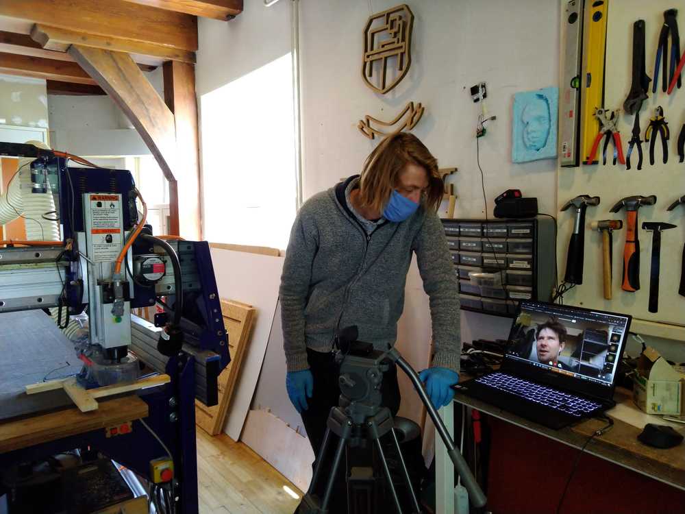
Rutger is answering questions from Harm about the Shopbot.
Local lecture
We will use a wax block to make the mold. Its dimensions are: 3.2 cm (depth) * 9.5 cm (width) * 14.5 (length). We use machine moldable wax.
Tips from Rutger
Mind your tools: if you use a 5 mm mill, for instance. Then make sure there is always 5mm space everywhere in your design so the drill can reach it.
Use a minimum edge of 5 mm but thicker is better.
Check length of mill. You must be able to reach lowest parts of your design.
In a two-way mold you need a hole to pour in the resin. 3 mm is too small. Better between 5mm-10mm
It is smart to add an air vent next to the pouring hole.
Remember that a mill cannot not make 90 degrees.
A two-way mold means that you have one mold that you use twice. They must be connected together.
Export a 3D model to OBJ, STL and then on V-Carve-pro you prepare for 3D milling.
Bubbles in your mold. Degassing chamber: physically suck out bubbles. Mixing: if you whip you will add bubbles. So instead mix it by making a Z. And keep scraping bottom and sides. Double decanting: Do mixing in one cup, pour over into other cup. Removes bubbles in between. Put mold in fridge for 2, 3 hours.
Resin
Transparant: Polyester. Needs a starter and you need to be very precise about that.
Polyurethane: most beautiful but expensive. Hard to use. It does not like moisture.
Epoxy: Slowest.
Smooth cast 325. Easiest to use. You put pigment in it to add a color on it anyway.
Cure time: the time it takes to harden.
Gel time: the time it keeps viscicosity.
Safety
- Always use gloves.
- On the use of respirators: not needed for silicon. You can use it for epoxy, polyester. You need a filter for bio, it is a brown filter. But if there is good ventilation, you do not need it. But ventilating can be a problem because it adds moisture to the air. A face mask does not have a purpose because that is against dust.
CNC machine
Software
Rutger explained how to use the CNC machine and then specifically for 3D milling. Henk has explained the milling machine in week07. But since I wasn’t able to try it myself at that time (due to corona) I took quite extensive notes again.
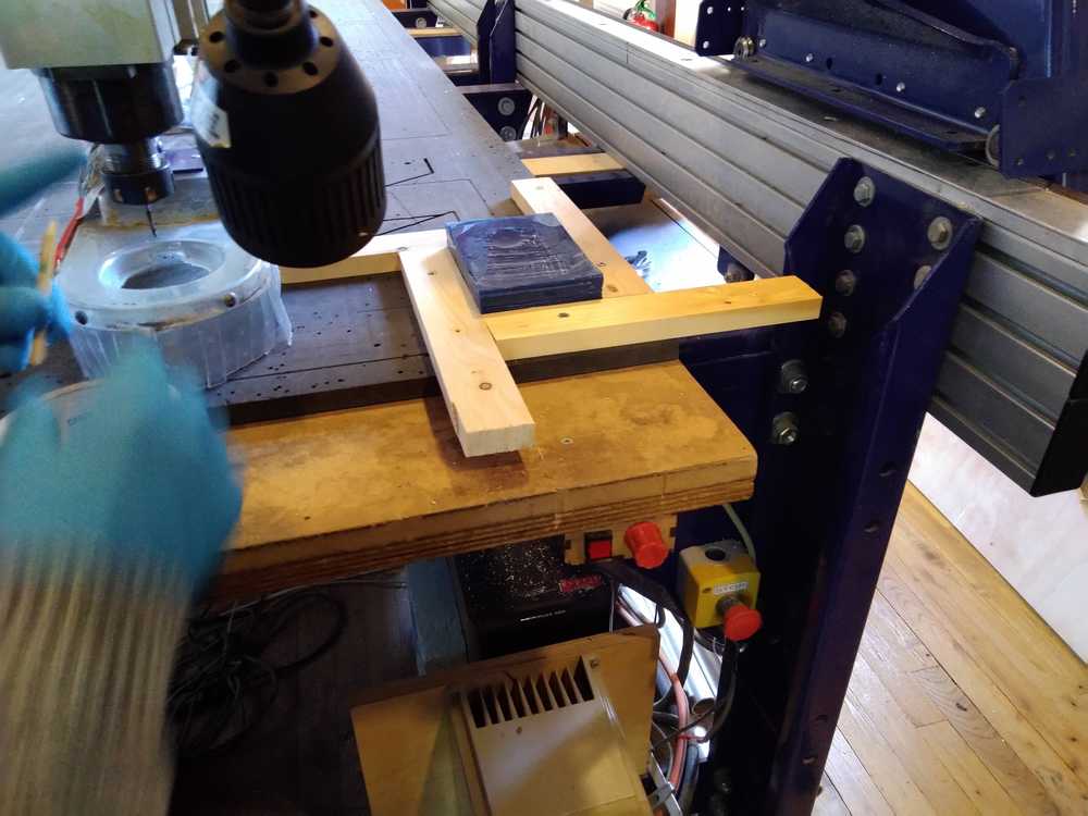 Stick the mold to the table with double-sided tape. Fasten with planks.
The wax blocks do not have perfect flat surfaces. But for you mold you want a flat surface. Therefore you grind a few millimeters from the top of the wax block to create a smooth surface. You can make this a separate design in your design software. But you can also do it in V-Carve. Click toolpaths on the right hand side of the panel. At the top it says Material Setup. Click and there will be multiple settings options given. One of them is start below the surface of the Z-axis. If you fill in 2mm here, the CNC will first drill out the top 2mm of the stock material. This will make it flat before drilling out the actual object.
Measure length of mill so you know how deep you can go. Don’t use all the length, leave a margin. Remember not to mill through the bottom of you mold.
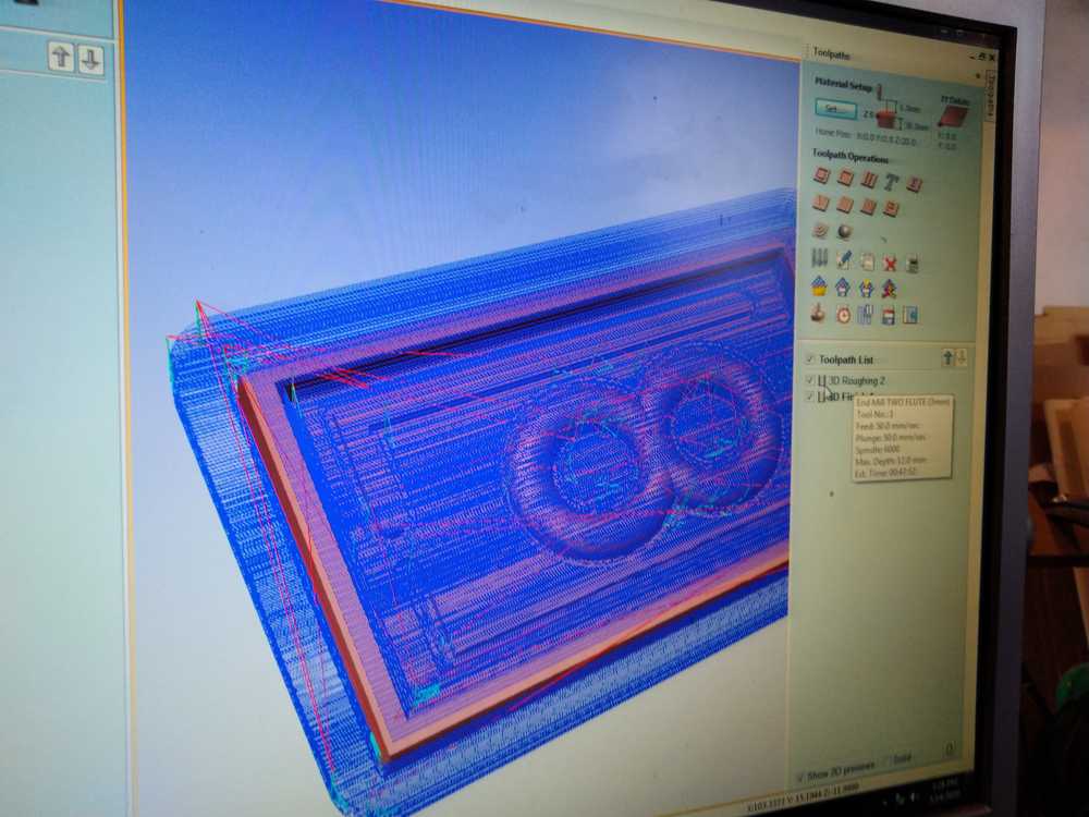
Open V-Carve:
 In the first panel you have to give the dimensions of your stock and select an orientation. Mark your X-Y axis on the left bottom site. Only after you have done that you can import an .STL file. Import STL as import component 3D model. Select orientation. Press okay and you will get an empty sheet.
Material setup. It does not know orientation. Choose left lower side. Zero plane: you can move object to the top of the material.
In the toolpath panel on the left the two lower icons are roughening toolpath and finalizing toolpath. You first select roughening and give it the settings you want. Here you can take the top 2mm of the material away to get a level surface. Then you do the same for finalizing toolpath.
At the top of the panel is the tool selector. Select this for each toolpath. Select the drill bit you need. Look closely at the settings. Fotr instance, for roughening you can have 45% stepover but for finalizing you want 5%.
Select your tool. F.i. 3mm two-flute drill bit. If you use 3 mm bit, also keep this in mind for your design.
Decide on path depth. Usually you’ll take half ot the diameter of the drill bit so: 3mm = 1.5 mm. It will go down 1.5mm per tool path. The stepover for roughing is 46%.
Spindle speed: much lower than normal. Wood: 18000. With wax: 6000.
Feed rate : 100 mm per second.
Plunge rate: 100 mm per second.
Machine limit bounderies: set it to model boundery.
Roughing stratey: lines going over the x-axis.
Plunge ramp: Rather then going straight into the material, it has a small angle. This is better for milling bit. We set it at 5 mm.
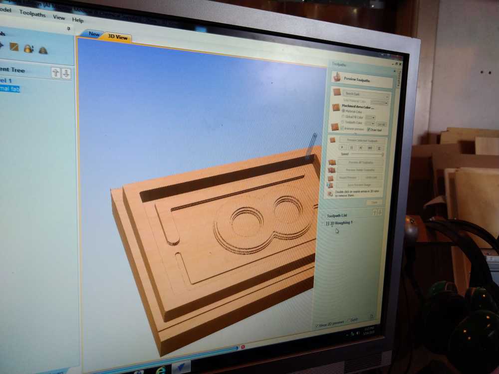
Press calculate. This will calculate the toolpath. Press review to see it in action. Press reset preview if you want to see it again. Don’t press calculate again, because then you will have multiple toolpaths. You can delete a toolpath by right-clicking on it.
Make material size same as model size. This is important.
We then do the same steps for the finishing toolpath.
Take the boundery of the model.
Offset: Don’t use an offset, because if the mill goes outside the material it will hit the wood.
We set roughing to 5% now, instead of 46% for the rough beginning.
Stepover set to 15 for the finishing toolpath.
 In the toolpath panel with the icons there is also an icon of a floppy disk. Use this to save your toolpaths. So after you pressed calculate you created a toolpath. These will be saved. If you use different drill bits for the roughening and the finalizing, you need to save the toolpaths as separate files. When using the same drill you can select one file.
You also have to save our V-Carve project. You do this in the V-Carve dropdown menu under file.
Machine
Clean the top.
Look around machine, is everything clear?
Turn on machine.
Open shopbot on computer.
Align machine, press zero x/y. The machine will move to its origin.
Press k. The yellow panel for moving the drill head appears.
Manually place the drill on the prefered x-y axis.
Go to the zero dropdown menu and choose zero x/y.
Save your x y axis. Make a picture or write it down, so you can place the drill back there if something happens.
Zeroing the z-axis.
Touch the plate against the drill. Check if the drill sees the plate by checking if a dot in the software lights up green. PLace the plate under the drill. Press the Z icon. The drill will now lower itself to zero itself.
This time we will not use the exaust because we want to keep the wax for reusing. Change spindle speed both in software and on machine.
Group assignment
Find safety sheet and datasheet of this material: You have A and B component and you have to read the safety sheet of both of them. A full description of the group assignment can be found on our communual page.
PMC 121/30.
Location of safety datasheet of PMC 121/30
Health
Hazards to health:
H302 Acute toxicity, oral - Category 4
H312 Acute toxicity, dermal - Category 4
H332 Acute toxicity, inhalation - Category 4
H315 Skin irritation - Category 2
H319 Eye irritation - Category 2
AH335Specific target organ toxicity-single exposure - Category 3 (respiratory)
H351 Carcinogenicity - Category 2
Health hazards: skin irritation, don’t swallow, serious eye irritation, may cause respiratory irritation, Suspected of causing cancer.
Not for kids.
Don’t breath it.
Wash with soap thoroughly after use.
Use outdoors or in well ventilated area.
Wear protective gloves, clothing, eye and face protetcion.
What to do when exposed:
Swallow: go to doctor, bring the material.
on skin: wash thoroughly.
Inhaled: leave the room with the fumes.
In eyes: wash with water, remove contact lenses. Go to doctor if it feels bad.
If skin irritation occurs: go to doctor.
Storage:
Store in a well-ventilated place, and keep it behind a lock. Label properly. Keep away from heat and sunlight. Reseal carefully after opening. Avoid water contamination.
Be advised: symptoms can be delayed and only occur after 48 hours.
Fire/heat
When on fire you can squelch it with: water fog, dry chemical, and carbon dioxide foam.
When heated material may expand and burst out of its container.
Environment
Don’t let it get into the sewer or drainage or open water ways. No special environmental precautions required.
Technical specifications:
Color: Clear Amber
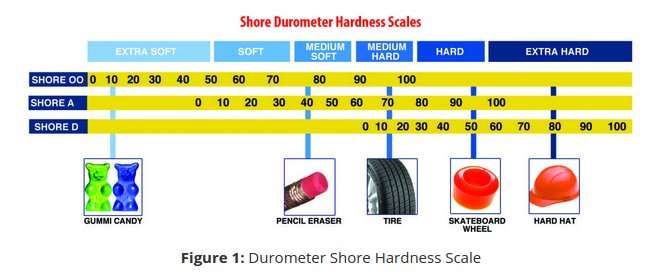
Shore Hardness: 30 A
Pot Life 30 minutes
Cure Time 16 hours
Shrinkage < .001 in. / in.
Instructions for use.
PMC121/30 is a urethane rubber. It is used to create a mold which in turn is used to create the model. (You also need a mold to cast the rubber. So the rubber mold is mold 2.) You can read the entire text here.
It can be used for casting waxes, Smooth-On liquid plastics, gypsum plasters and other materials.
Easy to mix and pour. You can add color by adding color tints.
Safety clothing
Wear safety glasses, long sleeves and rubber gloves to minimize contamination risk.
What mold to use
You use a hard mold for soft material and a soft mold for hard material. The hardness is defined by the ‘shore’.
Source: polytek
The Shore 00 Hardness Scale measures rubbers and gels that are very soft.
The Shore A Hardness Scale measures the hardness of flexible mold rubbers.
The Shore D Hardness Scale measures the hardness of hard rubbers, semi-rigid plastics and hard plastics.
PMC121/30 has a shore of 30A, which is defined as soft in the picture above. So I will use a hard mold.
Release agents
The PMC needs a release agent. This is stuff you spray over your first mold before you cast the rubber. This helps getting it out after it is cured. Like buttering your cake form before entering the dough.
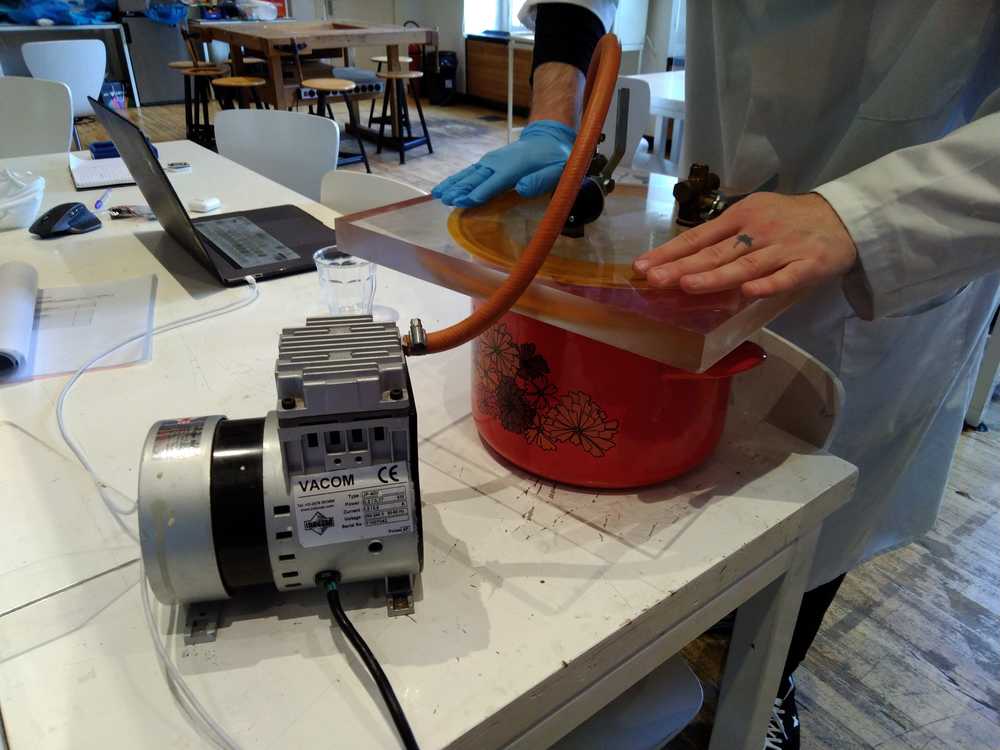
Preperations
Mixing: add equal volumes of Part A and Part B.
Mix thouroughly.
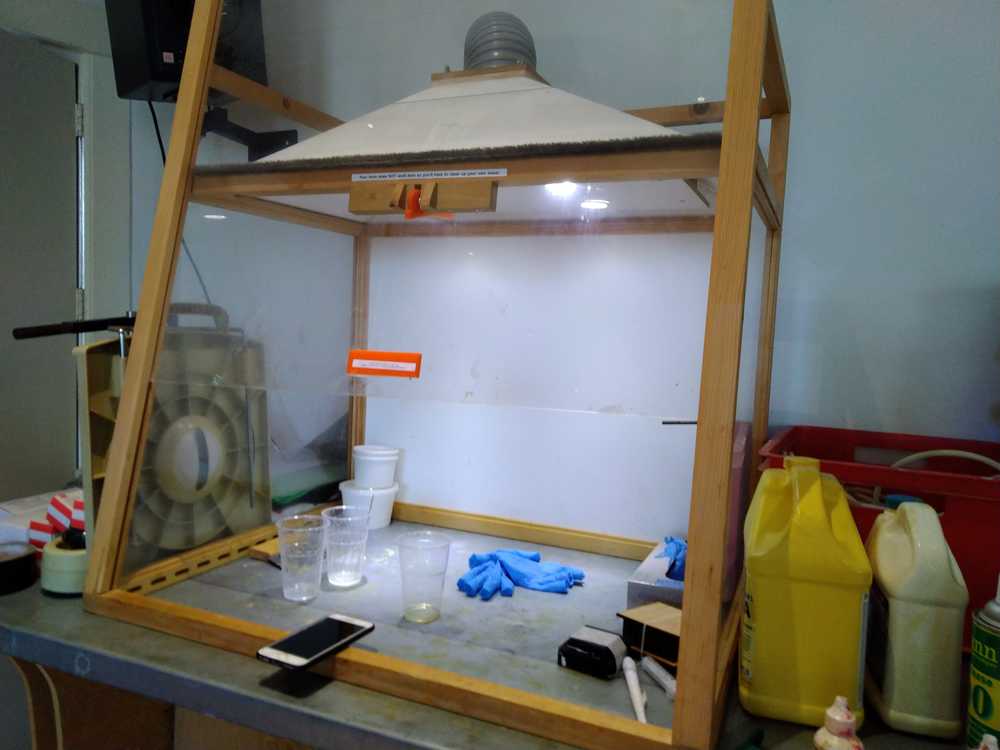
Our pouring and mixing station.
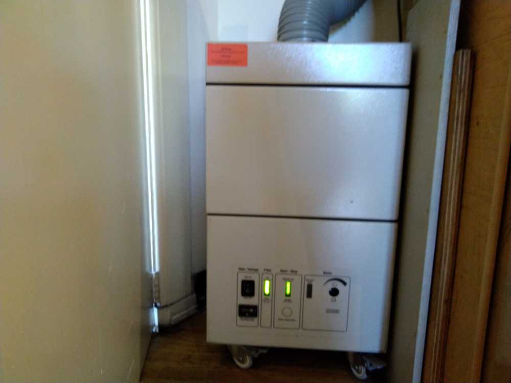
It has a fume sucker.
Put it in the degasser to remove air bubbles.
Apply release agent to the rigid mold.
Pour in the PCM into the mold.
Cure time is at least 16 hours at 23 degrees Celsius. Don’t set in temperatures lower than 18 degrees C.
Mind moisture it will collect it from the air and you do not want that.
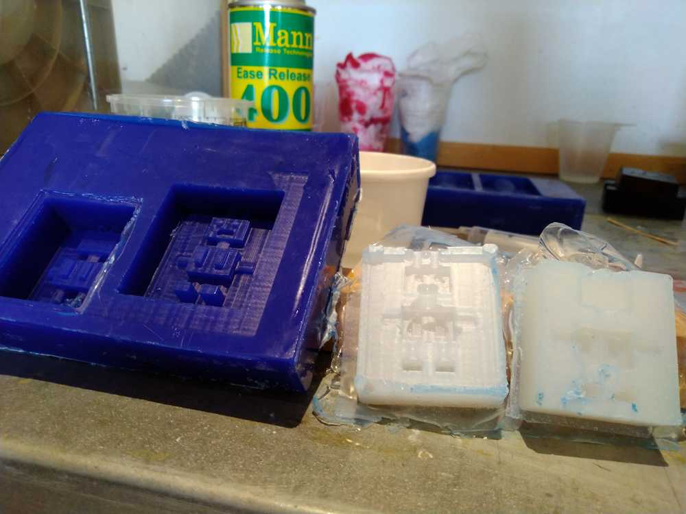
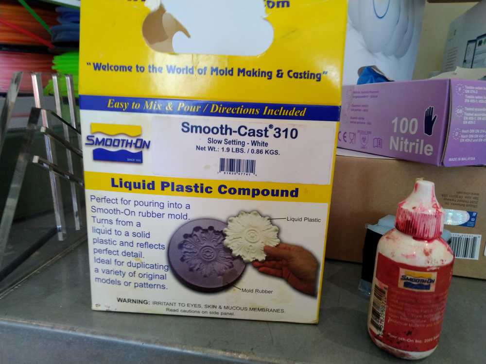
Smooth-cast 310
After researching the PCM I was it turned out to have cured in its container and was no longer usable. So for trying out a mold for the group assignment I used Smooth-Cast 310 instead.
It has a shore of 70D so I’ll use a soft mold.
It does not need degassing.
It can be colored with So-Strong which I will do color red.
Safety precautions:
Wear safety glasses, long sleeves and rubber gloves to minimize contamination risk.
It uses release agent. Let release agent dry for 30 minutes.
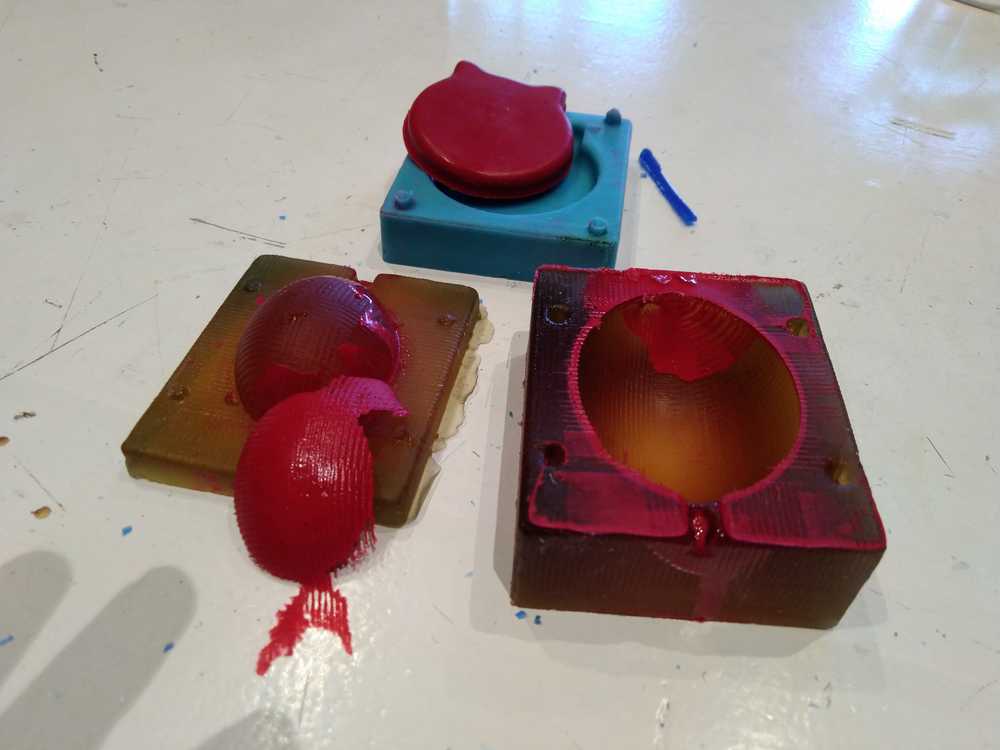
curing time 2 to 4 hours.
Outcome of the test pouring. The egg failed, the pour must have run out of the sides. The cat head came out nice.
What I learned from the group assignment
It is good to be made to look at the data and safety sheets because that way you learn that that information is out there. When I went to pour silicon for my individual assignment I knew I could look up all relevant info in the sheets.
The pouring was fun to do. And it helped that I already done a non-critical pour before I had to do my individual pouring.
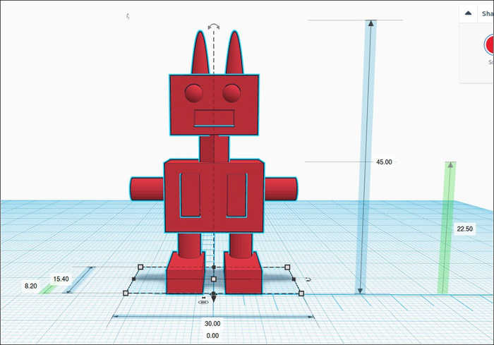
Individual assignment
I am going to cast the robot I made in week05 for 3D printing. Henk advised to take your model, put it in a block and then extact the model from the block. The block consists of two halves. To make sure the two blocks fit together you either use pins and holes or a lid-like structure. Pins: Place a pins on one half of the block. Substract those pins on the other half of the block. But Henk advised to use the lid-like structure is it is easier to design and works better.
I open the design from the robot in Tinkercad. To make a new project from an existing design you do CTRL-A (select all) and press copy. This must be done in the menu, do not use CTRL-C. Open a new project and paste the model in. Again in the menu and not CTRL-V.
Some Tinkcad commands I forgot:
Move object along Z-axis. CTRL + arrows.
Align: Shift-select two objects, then press align icon at top right.
Slicing object in two.
Next I have to make some adjustments to the model to make it castable. Some details must go and I have to make it bigger. Our smallest mill bit is 3mm so I have to account for that in my design.
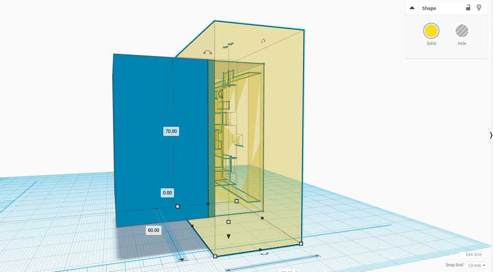
I don’t have the head for this. 3D designing a mold for a mold for a cast is a tasking mental excercise. Just when I was almost finished I realized I did it the wrong way around. The robot is an inverse whereas it should protrude.
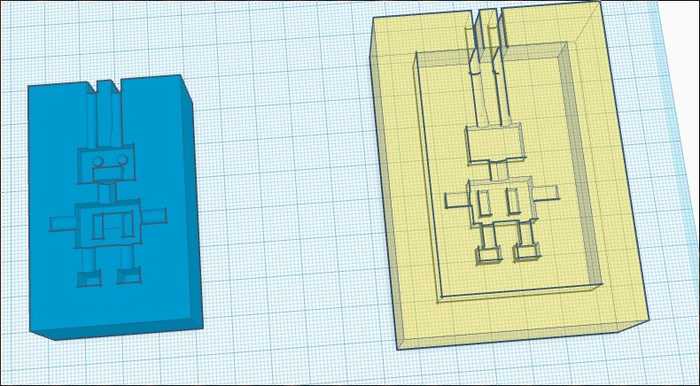
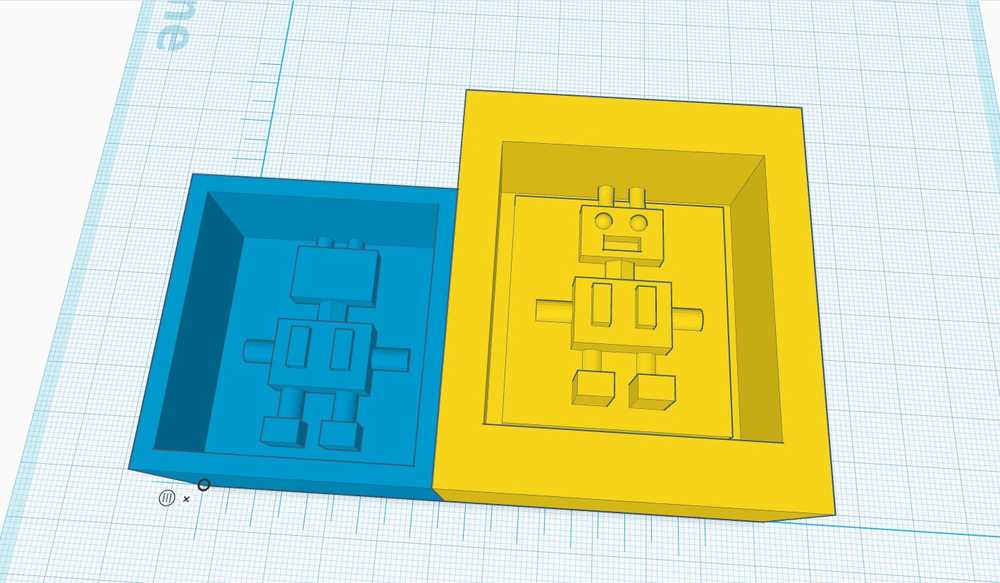
So I redid the design.
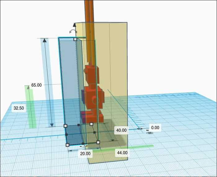
And here is the final result.
Milling
Wax block measurements: length: 144mm, width 97mm heighth: 33,6mm. Mill length: mill diameter:
Total length model: 115,00 mm, width: 70mm, depth 20 mm. (Height of the boxes are 30mm but they do not need to be milled).
I haven’t done the CNC milling yet so I am going to Write Down All The Steps!
Preparation
- First check if the machine is clear from stuff around it.
- Check clothes for loose cords etc. Put hair in bun.
- Collect safety clothing: gloves & safety glasses.
- clean bed of the machine.
V-Carve
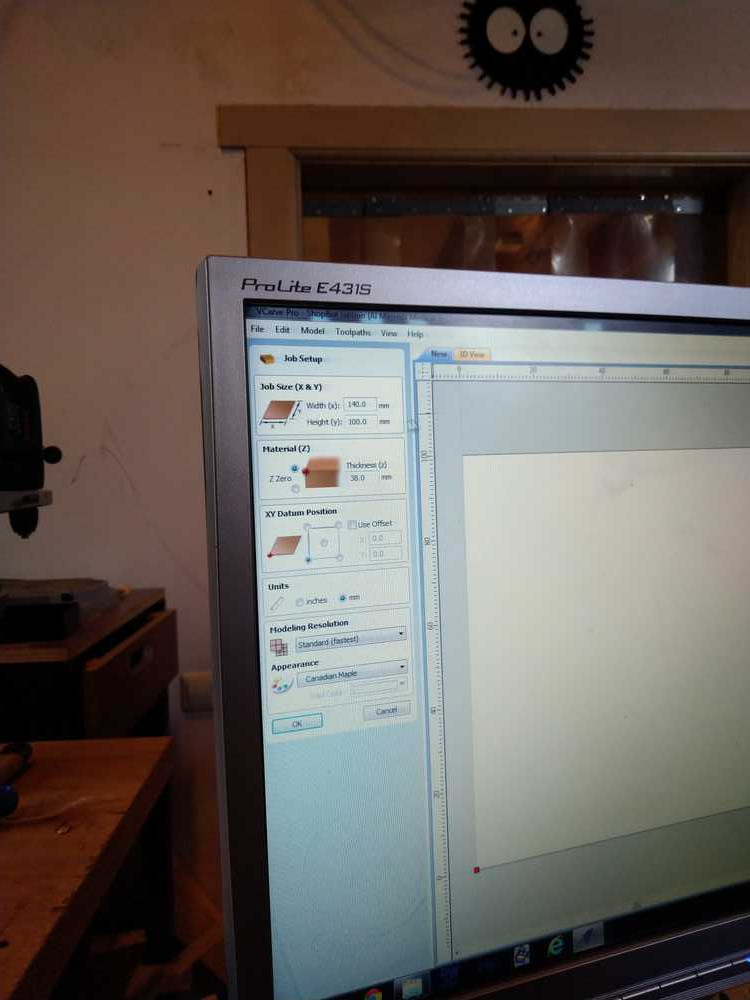
- Open a new file.
- measure dimensions of the wax block (see above) and eneter them under job size.
- under material (Z) choose top left for zero.
- XY datum position: lower left.
- Press ok.
Next panel:
1. Click toolpath on the right of the panel.
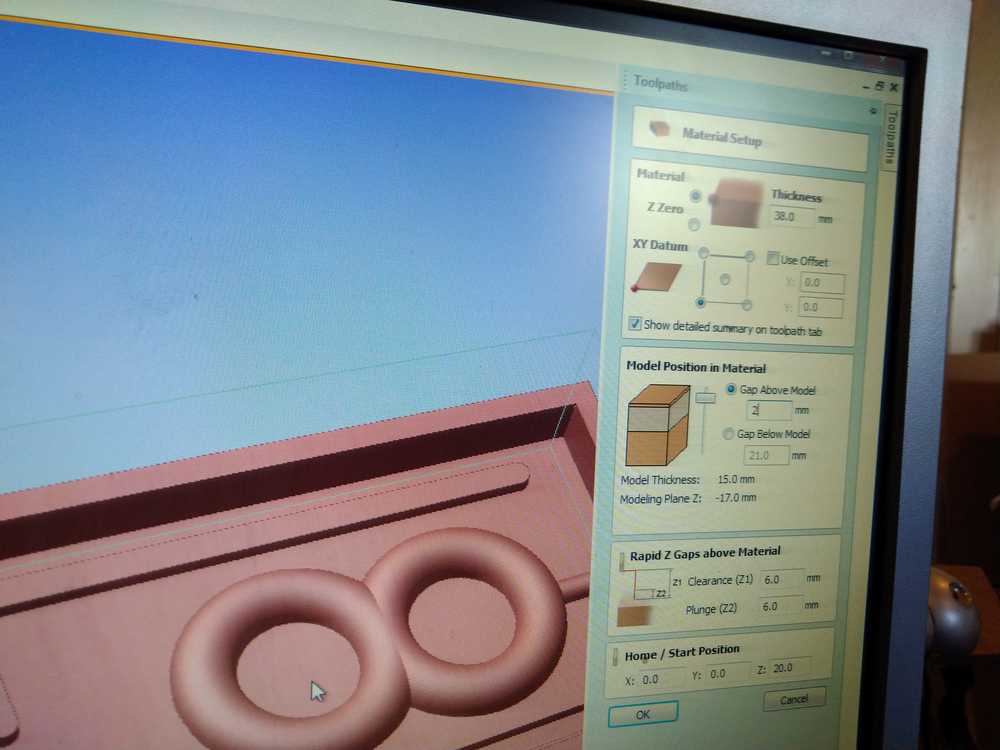
2. Click set under material setup. A new panel opens.
3. Z top left, xy, lower left. Keep ‘detailed summery’ ticked on.
4. Model position in Material: gap above model is 0.
5. Rapid gaps: 6 mm.
6. Home start position: x/y = 0. Z = 20 (you don’t want it dragging over the bed.)
7. Press okay.
Import component/3D model.
Orient 3D model. Move it so it is as you want in the stock material.
Under model size: click center model.
Zero plane position to upper or lower model in the stock material. This gives a slider to move your object up or down within the stock material. I ran into a problem here. There was a gray surface in the middle of the stock. The part of my model below that surface was grayed out and would not be milled.
I looked online and it turns out that an STL file brings along its own zero plane. This was the gray surface I was seeing. You can tell V-Carve to ignore the zero plane from the STL file by unselecting Discard data below zero plane. Here is the website from the software maker.
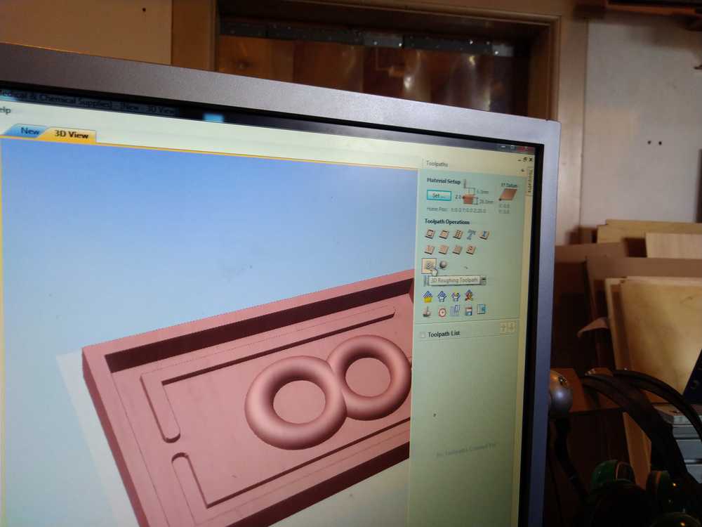
In the material setup panel, select roughening toolpath, it is one of the icons. I choose model boundery.
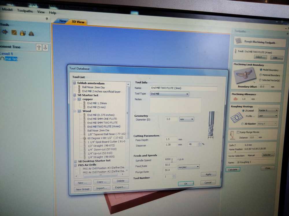
Under toolpath > tool database I choose 3mm two flute drill bit. I placed a 3mm square two flute drill bit in the collet, so that is what I select in V-Carve.
path depth 1.5mm; stepover: 5%; speed rate 6000, feed rate 80, plunge rate 80 mm sec.
I do the same thing for finishing toolpath: boundery of model; no offset; machine strategy raster. And I use the same drill bit: 3mm two flute square drill bit.
Saving: you need to save the file twice. First save the toolpath. This is not entirely straight forward. After you have calculated them you go back to the panel with the toolpath icons (where you found roughing etc.). Here there is also the icon of a floppy disc. Press it. Select both toolpaths. If you use the same drill, you can save them as one file. Different drills means two files.
Preparing the machine
First put on the CNC machine. This is the red button. You can put it on without having to put on the spindle. The spindle is turned on later by turning the key.
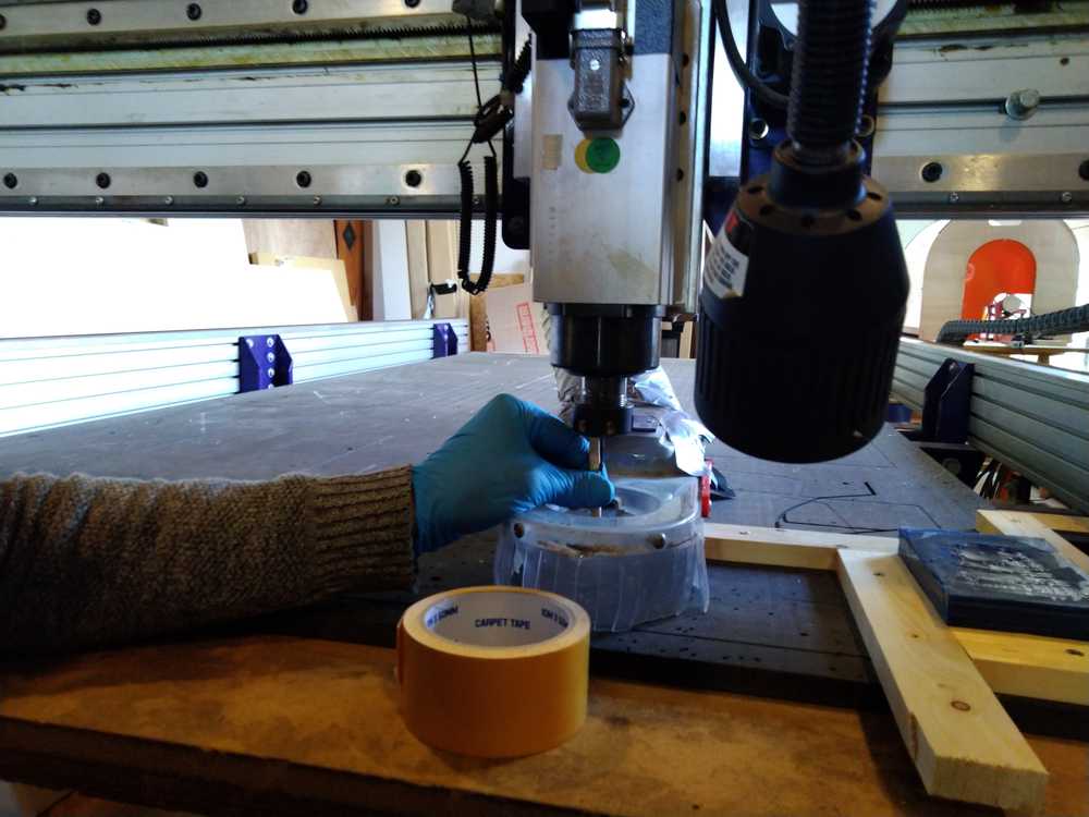
Changing the drill:
Lower the plastic protector by turning the butterfly screw loose. It does not need to come out completely. Lower the protector (it does not need to come off).
Turn loose the drill ring with the two iron fasteners. Keep your hand on under the drill it so it does not fall. Take out the drill then screw the collect entirely loose.
One mistake I made when replacing the drill was that I put it too far in. This would have ruined my model, because the drill head would have hit the wax. Lucky for me Henk spotted it and I lowered the drill bit.
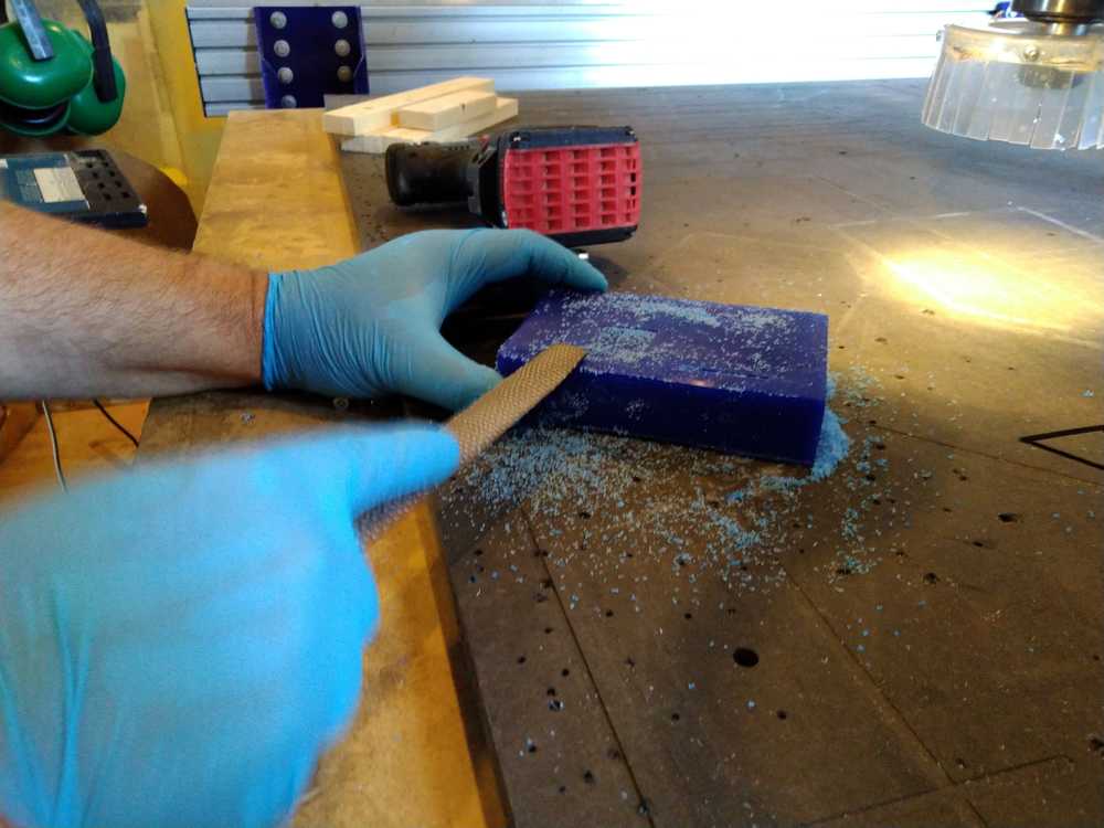
Fastening the wax block onto the bed. Place double-sided tape on one side o the tape. Use wooden planks to further fasten the block. This went wrong the first time. After a bit of drilling the block came loose. Milling had just started so we decided to turn the wax block around and try again. Henk said that the wax block did not have a flat surface. I had not thought about that and had not realized that that would matter. He filed off the round parts so it would stick better this time. I fastened the wood much more tightly the second time. And that time the block stayed fastened to the bed.
Shopbot software
You start by zeroing the axis. Normally you would click the XY icon at the top of the panel to bring the drill to the machine’s origin. But this is currently not working. The CNC machine has a temporary quirk. It can not find its own absolute origin anymore. So for now we no longer start with bringing the drill head to origin. Instead you bring it immediately to the origin above your stock material.
By pressing k you open the yellow panel with which you manually can move the machine. Use the arrows to bring the drill to required point. Then go to the dropdown menu (not the icon). Click on Zero and in the dropdown click X/Y.
Because of the quirk, you now often get a warning message: ‘x/y axis is outside the tables limits’ (or something along those lines). You can dismiss that warning with a click.
Zeroing the Z-axis. Use the metal plate attached to the machine. Tick it against the drill and look in the software if a button lights up green. This means the drill is recognizing the plate. Put the plate on the stock material to zero the Z axis. The top of the wax was not straight so Henk advised to find the lowest point and hold the plate there. The end of the plate had to be as close to the drill as possible. Because the plate is forced upwards by the unequal sides of the block. This would place the drill higher than the actual material.
Zeroing the Z-axis - final version
In week07 we learned about zeroing the Z-axis but then corona measures came into force and I did not work on the shop bot. I still had some uncertainty on zeroing the Z. Until now it has stood as a question in my documentation in week07. Now I will go back and adjust it.
- put the plate steady under the drill. Don’t touch it while it is zeroing.
- Touch the drill with the plate and check if the green button lights up.
- Click the ICON Z. not the dropdown menu. Not the 0.0. But the Z icon.
- The Z-axis will now zero itself.
- Manually make the Z go up.
- You don’t need to confirm the levelled Z. This is the entire process.
Zeroing the X/Y axis
Same as for the Z: here is the final version for zeroing X/Y.
Bring the drill to the desired pont. Use the dropdown menu (not the icon!) Zero > zero X/Y.
Shopbot virtual mode
If you open the software before you have started the machine, it will start in virtual mode. You can see that because an extra blue panel will open. Simply closing the program, starting the machine and reopening the program is not enough. You need to close the virtual panel. Otherwise the software will startup in virtual mode even if the machine is on. So: close blue panel, close software, start machine, start software.
Drilling
Now you can drill. Load the V-Carve file into the Shopbot software. Turn on the spindle with the key. Check if the spindle speed is right: 6000. Or adjust manually at the little box below the machine. Then you can press okay and the machine starts drilling.
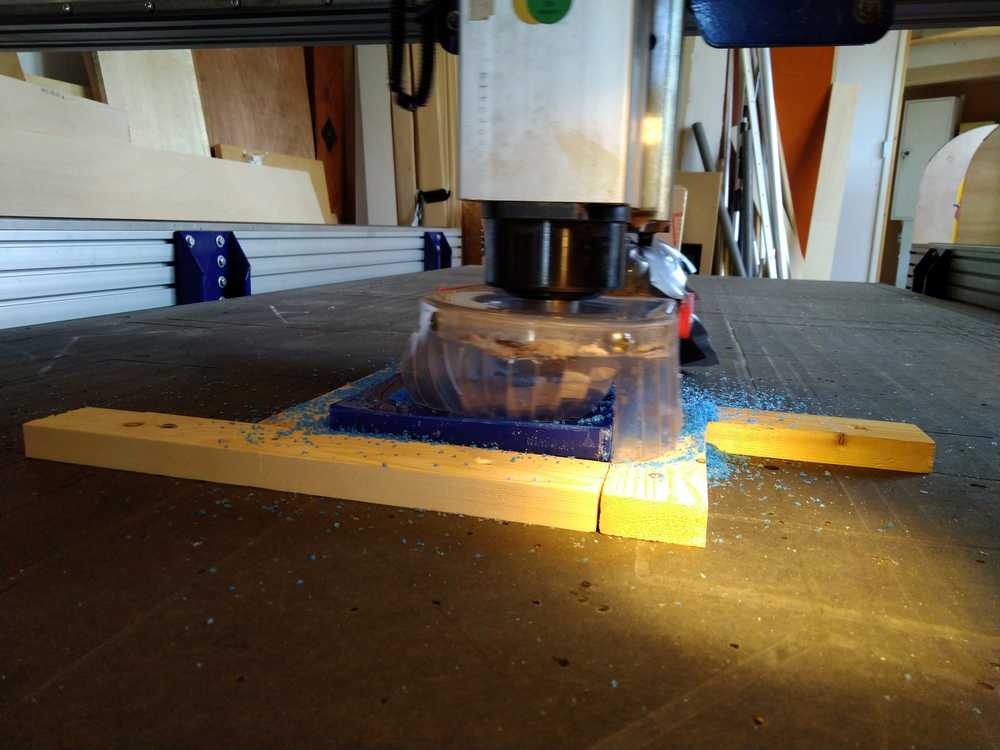
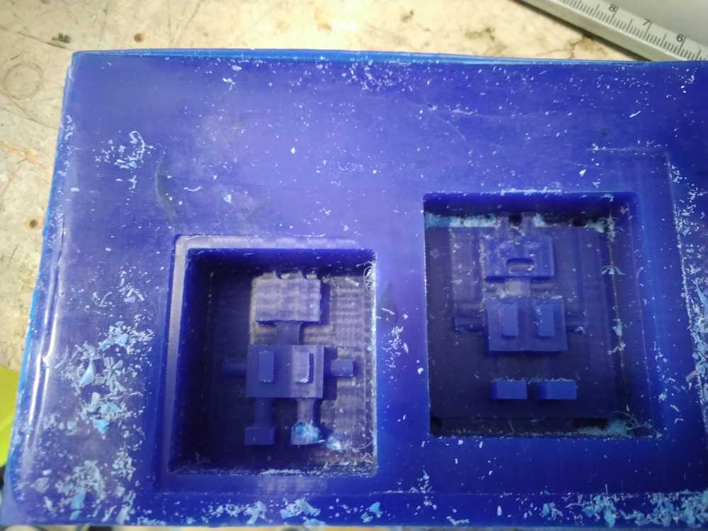
The finished mold.
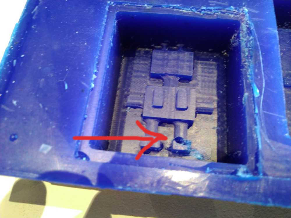
It did not come out entirely okay. At the bottom there should be a trench drilled out for the other box to fit in. It was drilled at the top and the bottom but not at the side. So I tried to get that done with a knife.
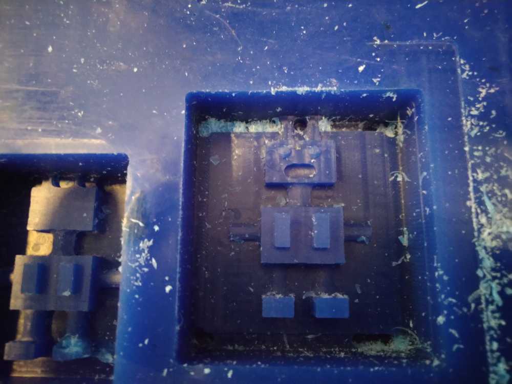
But as I am working with the knife I realize I made another grave mistake in my design. The boxes are made to fit into each other. But the way the two robot halves are positioned is not correct. Its face and the back of its head are facing each other when the boxes are fitted into each other. That is the wrong way around.
In this picture you can see that when to boxes fit together, the robot’s head halves are facing each other. Which they should not.
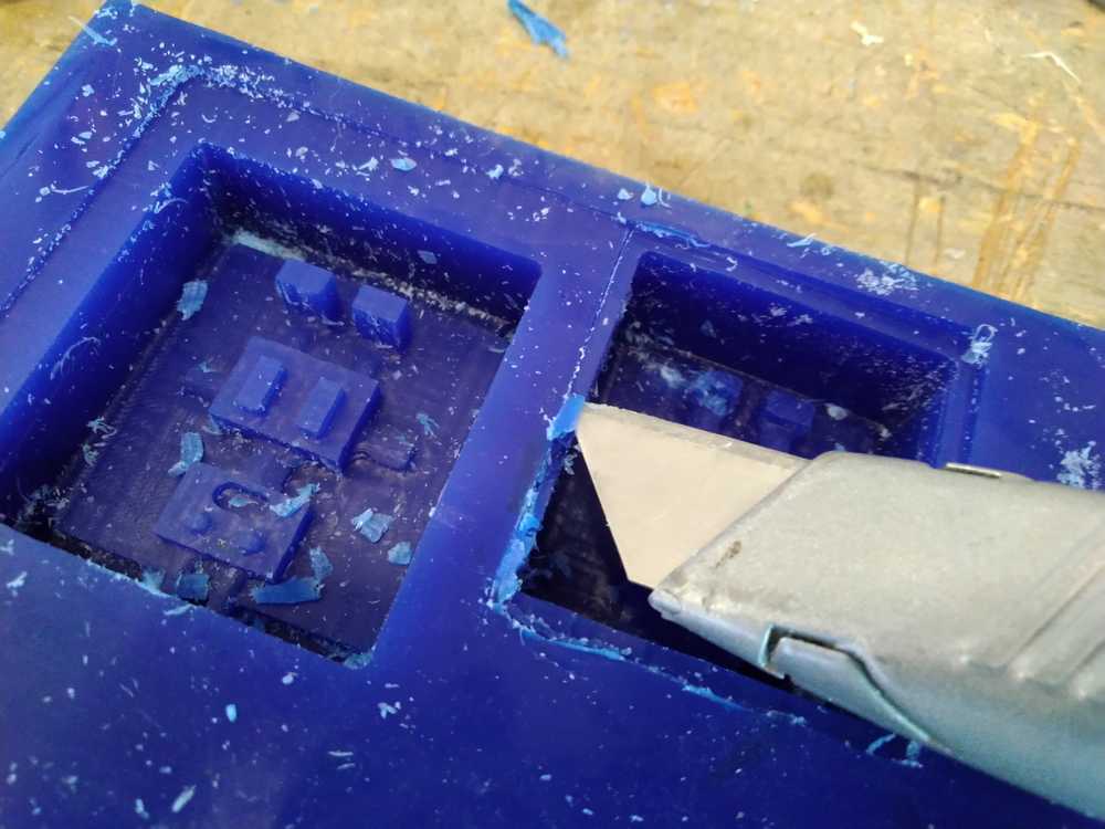
So my idea of fitting the box into each other will not work. So there is no reason anymore to carve out the trench of the box with the knife. Instead I will clamp the mold together with a glue glamp.
The longer I look the more mistakes I see. As related earlier, the wax block came loose from the milling bed. I turned it around and used the other side. Now I see that one drill hole comes through the foot of the robot.
I take some wax, cut it up and place it into the hole. Then I heat up some of the wax and drip it over the foot to close the hole.
Casting
First silicon cast
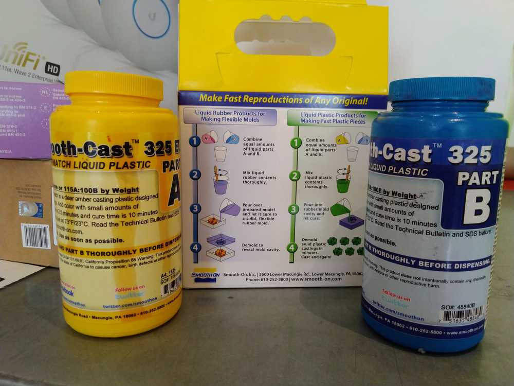
The first cast is a pour of silicon into the CNC milled wax mold. We use ‘Silicon Additie Transparant 15 Fast’. Here is the product page (in Dutch.) It is a skin friendly silicon that hardens super fast, within 15 minutes you have a solid casting. You need to take this into account when pouring. It cause some slight problems for me, see below. The product consists of two parts: The A and the B component. You should have 10 parts of A product and add 1 part of B component.
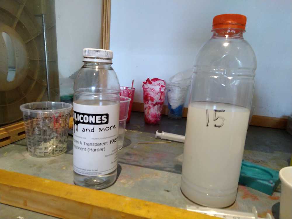
The unlabeled bottle is the A-component. Ten parts of that. The small bottle is the B-component you need 1 part of that.
Here are the technical details.

Safety precautions are mild. They advise to use gloves if you use the product often. I wore a lab coat to protect my clothing. A respirator is not necessary.
Rutger gave some good advise on how to go about it. First, fill your mold with water and pour the water in a measuring cup. Now you know how much volume you need to fill your mold. I needed a little more than 60 ml (I thought). So I used 60ml of the A component and 6ml of the B component. Rutger advised to use a seringe to measure the B-component volume precisely. So that is what I did.
I mixed, stirred and poured. And then, despite rutgers advise, I did not have enough volume. So I poured a little bit in the second square of the mold and had to quickly make new silicon. This was not a good idea. The little bit that was already in the second square started hardening, but without the pressure of the rest of the volume on it. This has consequences as we shall see later. I cleaned up the pouring station and left the mold for the night.
The next morning it was time to check the castings.
The pour-in-two-sessions action is not a good idea. The square I did that to has some serious bubbles. I asked Henk if I could recast the silicon. But he said it be more interesting to find ways to fix the current mold. And he is right so that is what I will do.
Another thing that has not come out well are the pour and air holes (the antenna’s of the robot). There is not enough of a barrier between them and it will probably result in one flat antenna. I will try and remedy this by adding a bit of stick to the mold to serve as a separation.
Oh! and the biggest surprise of all: I did not make a mistake in the design with the robot faces being the wrong way around. The mold works. So that was a nice surprise!
Second liquid plastic cast
For the second cast I used Smooth-cast 310 that I also used for the group assignment. And a colorant to make it red. You only need one or two drops of the colorant.
I forgot to add a release agent. We will see tomorrow how grave a mistake that is.
I wanted to add some strength to keep the two halves of the mold together. First I tried using a glue clamp. But this put so much pressure on the silicon that it was being squeezed out of form. Harm strongly advised not to use it. So instead I used tape. The stick at the top is to separate the two antenna’s.
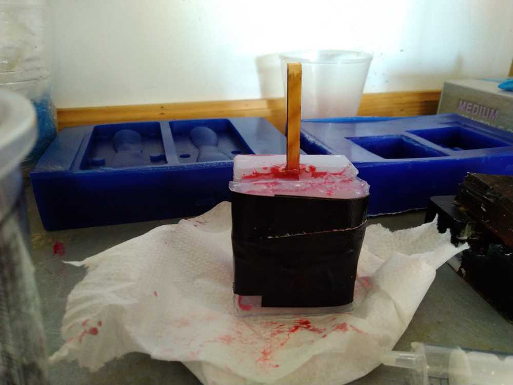
Now we have to wait 24 hours.
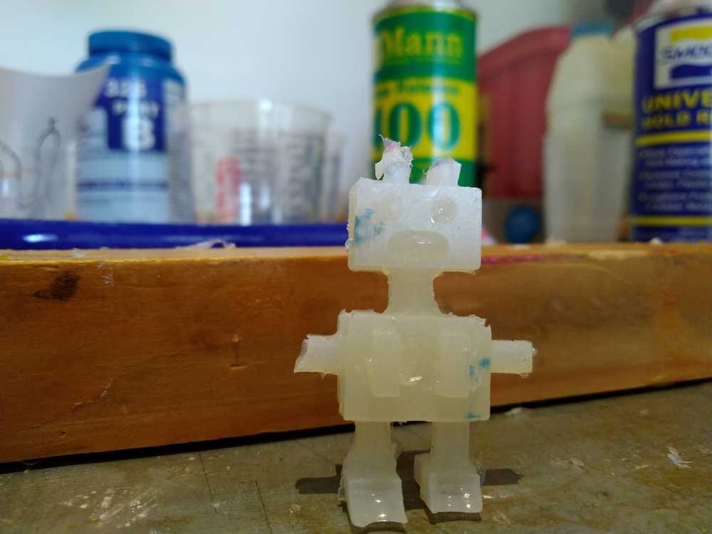
Final object
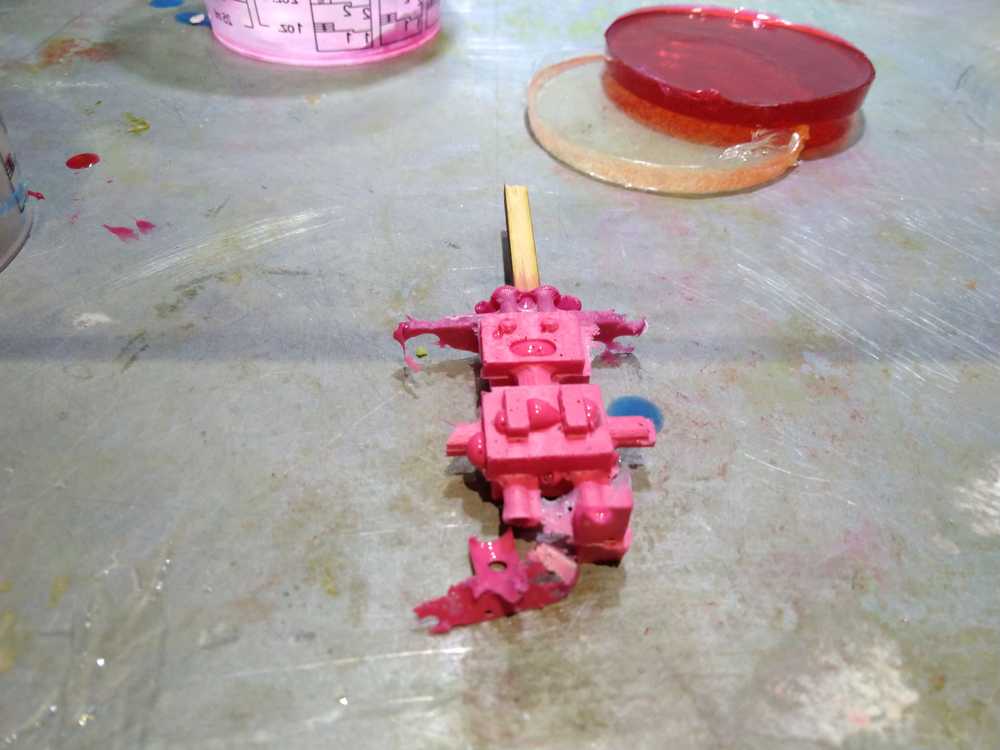
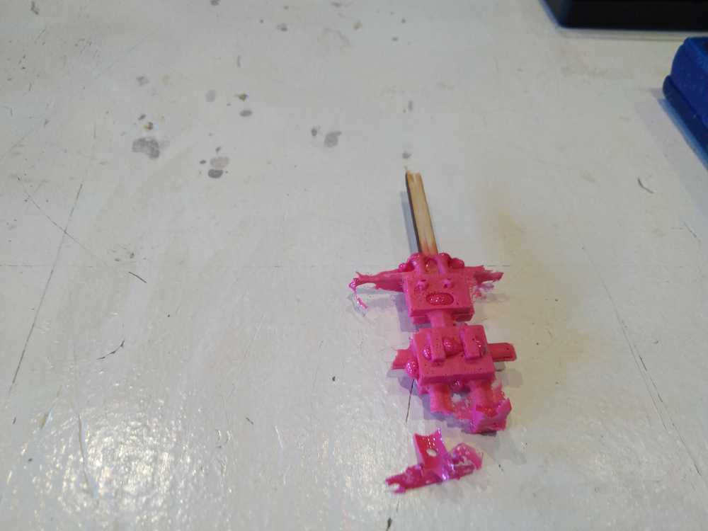
This is how my object came out. There is a lot wrong with it.
First, the bubbles in the second cast are problematic indeed. You can see bulges on the robot where they should not be, especially on its torso.
Second, the stick I wanted to use as a divider to compensate for the non-closed air and pouring holes, well, it is stuck to the mold. I should thought about that. But it does give ideas. You can stick things in your mold should you want to.
One of its feet did not get casted right and came off. Or rather, was never attached.
Strangely, the drilling hole of the wax block mistake is visible on the dismembered foot. Even though I fixed that with heated up wax.
Drilling hole has mysteriously reappeared!
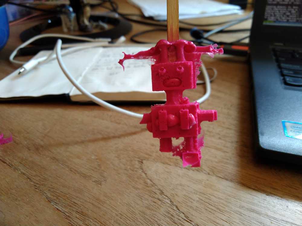
The two halves of the mold aren’t entirely synchronized. They are off by about to millimeters.
There is plastic stuck to the top of the mold. The robot now has Yoda ears instead of antenna’s. I should’ve swiped the mold clean after pouring.
Second try final object
It is Wednesday morning so not much time left. But lucky for us we have resin at the lab that cures in 10 minutes. So I made a second cast in which I try to remedy some of the problems with the first mold.
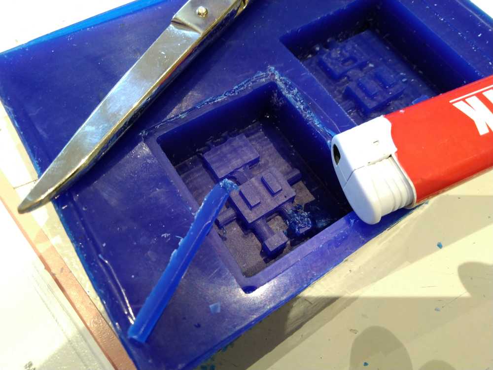
First I fill the bubbles in the mold with with wax. I liquidize it by heating it up with a lighther and fill the holes.
With a Stanley knife I remove some protruding silicon from the foot. It is only a thin layer but it might have been the reason the foot was not cast right and fell off. 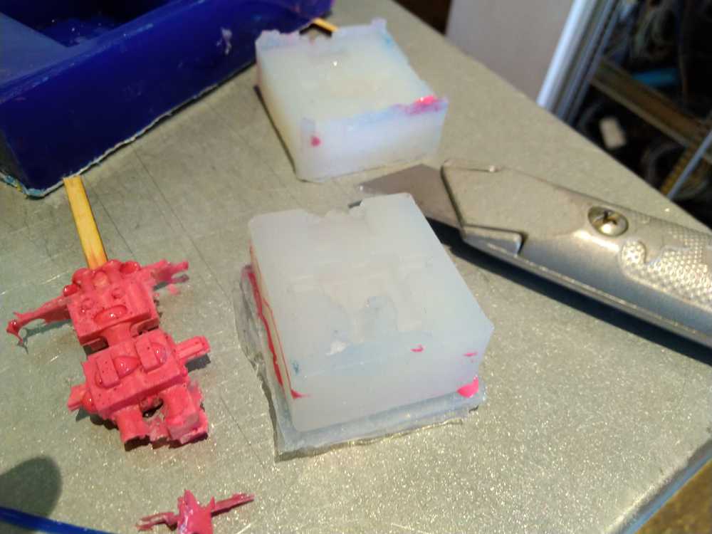
I used Smooth-Cast 325 for the second pour. Because of time constraints I did not look up the datasheet etc. But Hyejin had used it before and she explained how to use it. Mix parts A and B 1:1. Stir quickly and pour quickly because it hardens really fast. You need not use a respirator. I wore gloves and a lab coat. I again forgot to use a release agent but in the end the object easily came out out of its mold.
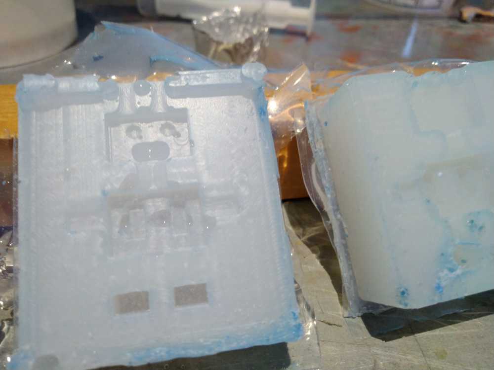
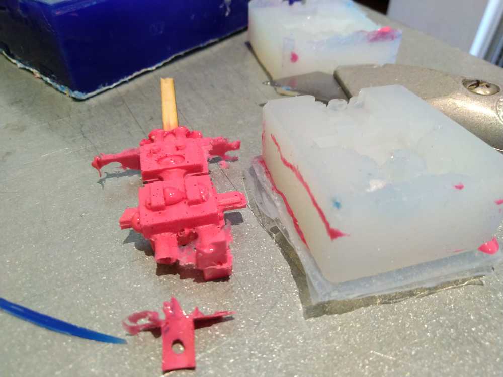
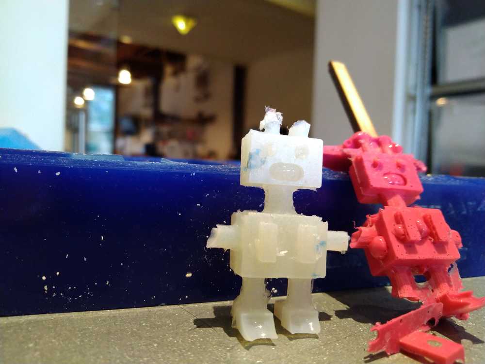
The second pour comes out much better. Here I have removed half of the mold. This side of the robot comes out really well. It’s foot is a bit messy, but that is from fixing the drill hole.
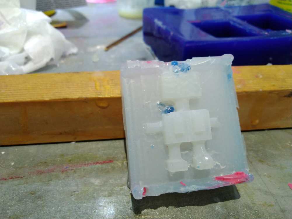
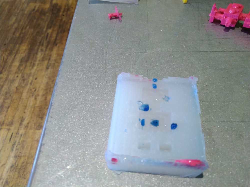
The other side is the more problematic side. Here you can see the wax added to fix the holes attached to the object. Will it come off properly?
Yes! The wax solution actually works pretty well. In most places it just comes off and has filled most of the bubbles. The protruding bulges on the torso and other places are gone. It’s a bit rough, not very neat but a big improvement.
The antenna’s are improved too. They are not as nice and neat as I would have hoped. But at least they are to separate entities. The feet’s holes of the mold haven’t entirely filled up during the pour, so not the robots has some sort of toe formation rather than square feet. But the robot can stand on its own ot feet. I use the Stanley knife to remove some excess silicon. I realize that if I would make a plastic pour that would not be possible.
What went wrong
Well a lot but I must say that the entire process is more forgiving than I would’ve expected. You can patch things up along the way. For the milling: next time I’ll take much more care to fasten my stock material properly. Ruther advised to take of the top 2mm of the block before having it start on your design. I did not do that and the top of the mold was messy because of it. The protruding edges that should’ve slid into the trench only came out half. I gave a lot of thought to the design and the CNC machine. But the casting I just sort of did it without thinking much about it. Like pouring in material when you know you don’t have enough. And not wiping the cast clean after pouring and have Yoda ears stick to your object. More precision is requireed here too.
What I learned
I’ll trust the precision of the CNC machine more. I made two boxes that neatly slide into each other in TinkerCad. I would not have been surprised if the machine had been some tenths of millimeters of that would make the boxes not slide into eachother precisely. But this was not the case. That is good to know for future designs. I quite dreaded this assignment to be honest. I knew the 3D design of a mold of a mold of a cast would be problematic for my spatially impaired brain. The CNC machine was also quite daunting because I had not used it before. The designing was no less hard then I expected. The only surprise there was that in the end I did not make a spatial mistake. But the CNC machine, I quite love it now. It delivers really cool things. But more then any other machine you need to keep your head and attention focused on it.