7. Computer-controlled machining
Amsterdam, March 11, 2020
To do
| Description | status |
|---|---|
| Group assignment: test runout, alignment, speeds, feeds, and toolpaths for your machine | done |
| Document my part of the group assignment | done |
| CNC machine: finish documentation before using the machine | done |
| Make a design for the CNC machine in FrreCad | done |
| Mill the design on the CNC machine | Done |
| Assemble the design | |
| Document my individual assignment | Done |
Source files
| Description | link |
|---|---|
| FreeCad project for cabinet design. The first 2D one. Was not used. | Downloadable zip. |
| FreeCad project for cabinet design. The second #D one. Was not used. | Downloadable zip. |
| Downloadable SVG from TinkerCad design | Downloadable zip. |
| DXF file from the TinkerCad design exported via Inkscape to DXF | Downloadable zip. |
| Final design: SVG + DXF | Downloadable zip. |
urls
| Description | link |
|---|---|
| Index of this week’s topic | http://academy.cba.mit.edu/classes/computer_machining/index.html |
| Global lecture video | https://vimeo.com/397463603 |
| Global review video | https://vimeo.com/398805127 |
| Recitation video | https://vimeo.com/398366066 |
| Group assignment documentation | https://fabacademy.org/2020/labs/waag/groupAssignments/week7.html |
CNC machine how to
Safety
Safety is very important for the CNC machine. There can be physical injuries: flying pieces, moving bridge, moving drill.
There can be fires if hot wood chips are sucked into the dust collector.
Don’t touch
When the machine is on, don’t touch it. Don’t lean on it. Don’t put your hand on the rail or bridge or anywhere. The bridge is moving and will go over your hand.
When the machine is on, this is absolutely forbidden. The bridge moves and will severely hurt your hands. Don’t touch the machine when it is on!
Clean
- clean the machine bed.
- clean around the machine. Pieces leaning against the machine will cause damage.
Clean around the machine. Loose material touching the machine can will cause damage.
No mistakes
In other weeks mistakes are ways to learn. In this week mistakes can cause damage.
Take your time / don’t be stressed
Be in zen mode when operating the machine. Don’t start a job when you are under time pressure. Don’t start a job when you are stressed
Emergency exit
Take note of the emergency exit. Where is it, how does it open, where does it lead.
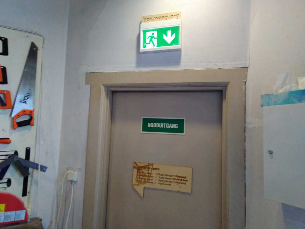
Locate your emergency exit.
Fire extinquisher
Locate where the fire extiquisher is placed and make a mental note.
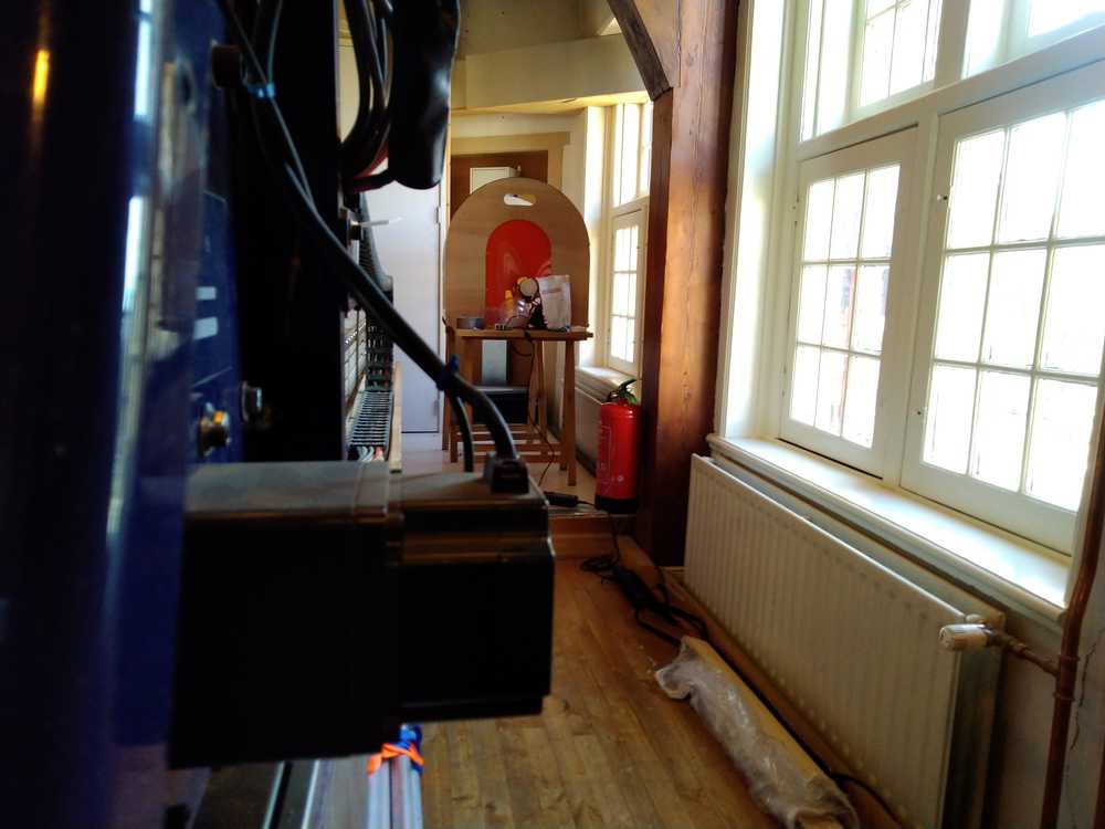
Locate the fire extinquisher.
No loose ends
Check your clothing.
- No cords dangling from your hoody.
- No scarf around your neck.
- No loose shoe laces.
- No loose cords, belts , strings, etc.
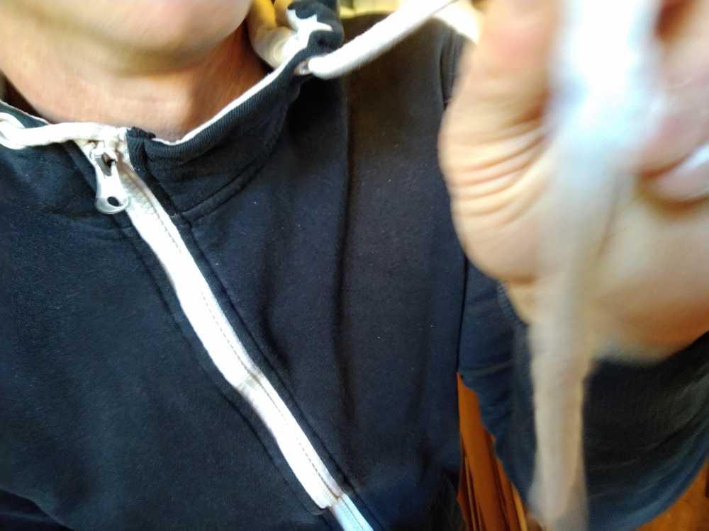
No loose hoody cords.
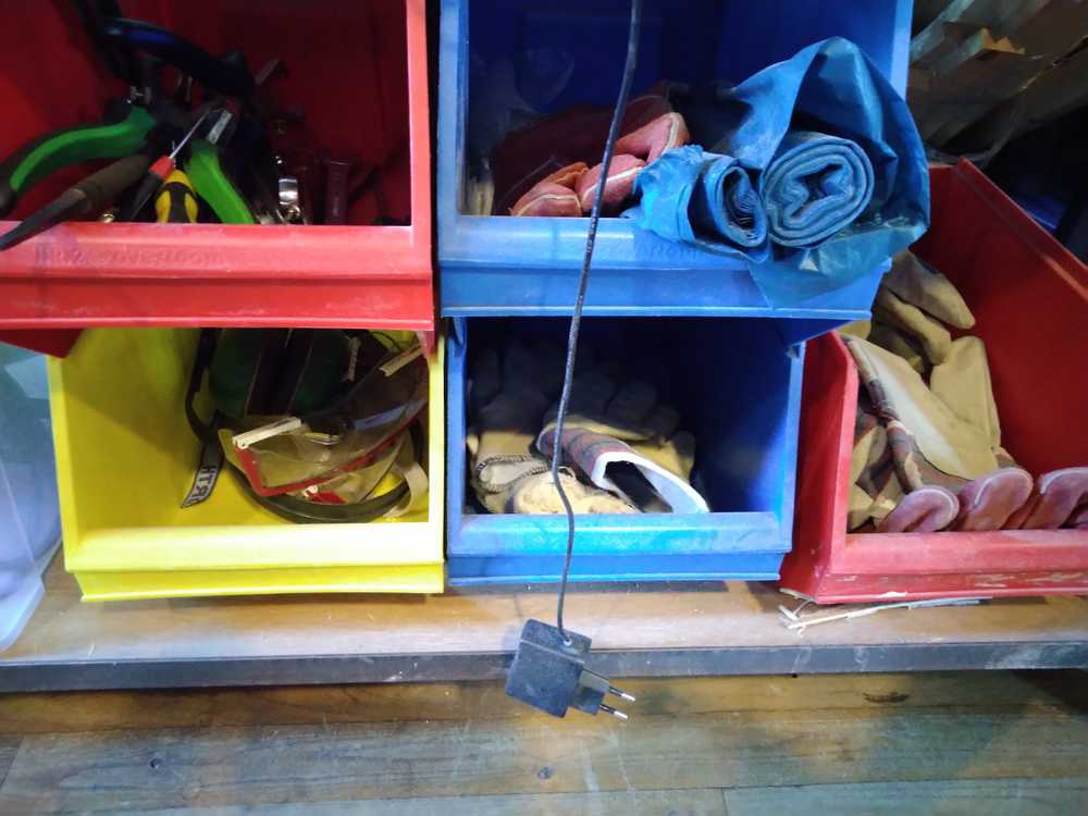
Safety clothing
Collect all safety clothing you want to use: safety glasses, gloves, ear plugs and place them in the vicinity of the machine.
Dust collector
When heated wood chips enter the dust collector, remove the inner sack. Even when you think it’s okay. One smoldering chip can cause a huge fire.
Spindle keeps moving!
When you stop the machine, the spindle will keep on moving. This will result in heated wood dust and chips. So when you stop the machine, lift the Z-axis.
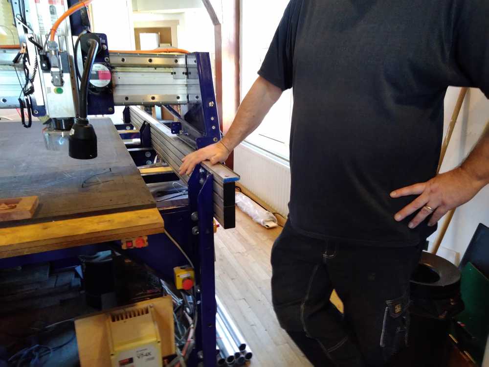
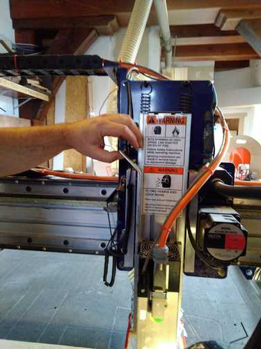
Machine parts
Just like the small milling machine, the CNC works with x-y-z-axes.
It also has a sacrafical layer on the top of the bed.
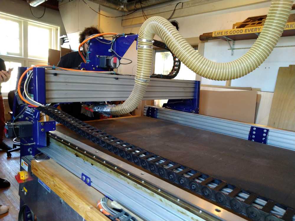
CNC bed, bridge and dust collector pipe.
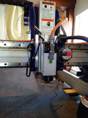
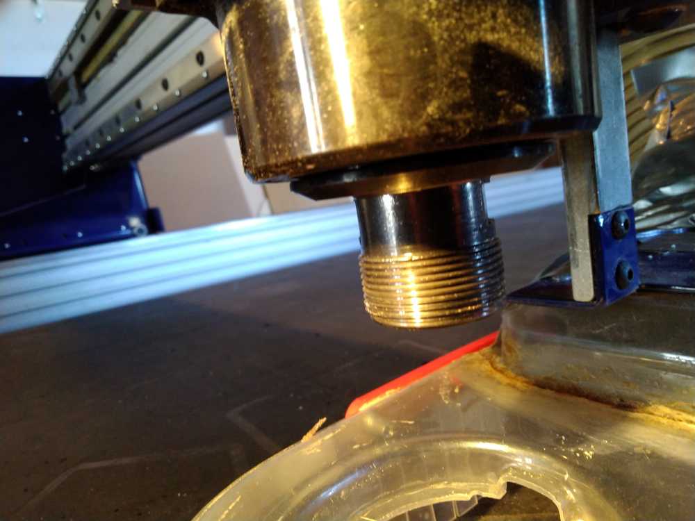
Milling head of the CNC. At the bottom is the spindle: speeds of up to 18.000 rounds per minute.
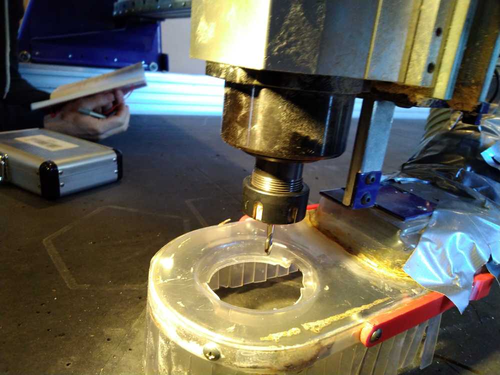
Spindle and drill of the CNC.
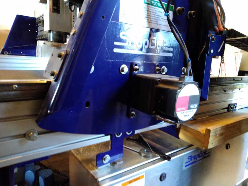
Stepper motor: The CNC has several stepper motors.
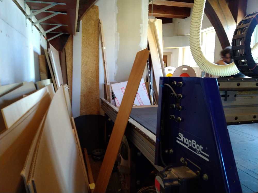
The dust collector is a big vacuum cleaner that sucks the wood dust and chips from the milling bed. It is located in the back of the room. It has a huge sack in which the dust is collected. When heated wood gets sucked up, the sack must be taken out and placed outdoors immediately.
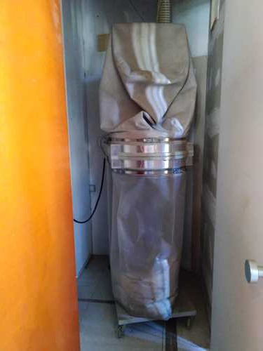
Dust collector.
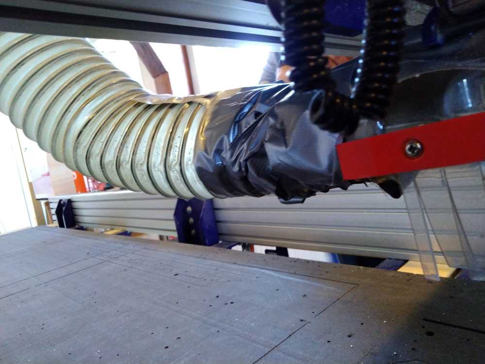
Pipe from the CNC milling part to the dust collector.
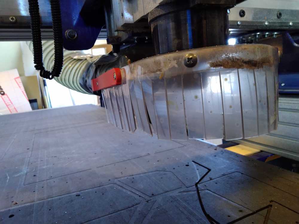
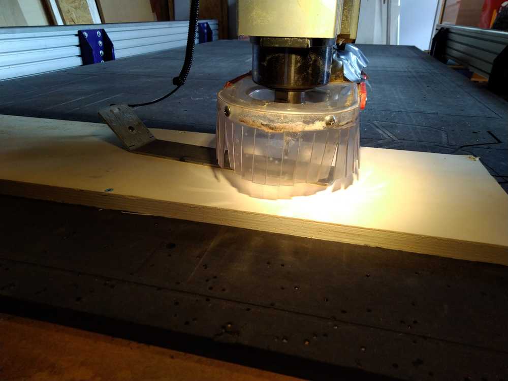
The skirt surrounds the milling head.
Using the CNC machine
Emergency break
- Stop the machine.
- Lift the Z-axis.
- Go to dust collector and thoroughly inspect the bag for hot wood.
- When you’ve seen sparks, always remove the dust bag.
- Do not resume milling afterwards. You will be stressed and that will impair your ability to operate the machine safely.
Always remember:
- Never touch the machine when turned on.
- Spindle keeps on moving even if you stop the machine. This results in heated wood dust and chips.
Preparation:
- Get into Zen mode.
- Check your hair. Put long hair in a bun.
- Check your clothing. No cords dangling from your hoody. No scarf around your neck. No loose shoe laces. No loose cords, belts , strings, etc.
- Put on safety protection clothing: safety glasses. ear plugs, gloves, shoes
- clean the bed of the machine.
- clean around the machine.
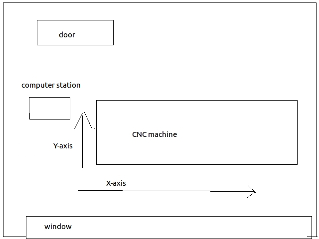
Orientation of the X-Y axes
There was some confusion about the X-Y axes of the CNC bed. But we disucssed it at the local review and reached certainty. Here is a representation of the CNC room and the X-Y-axes in relation to it.
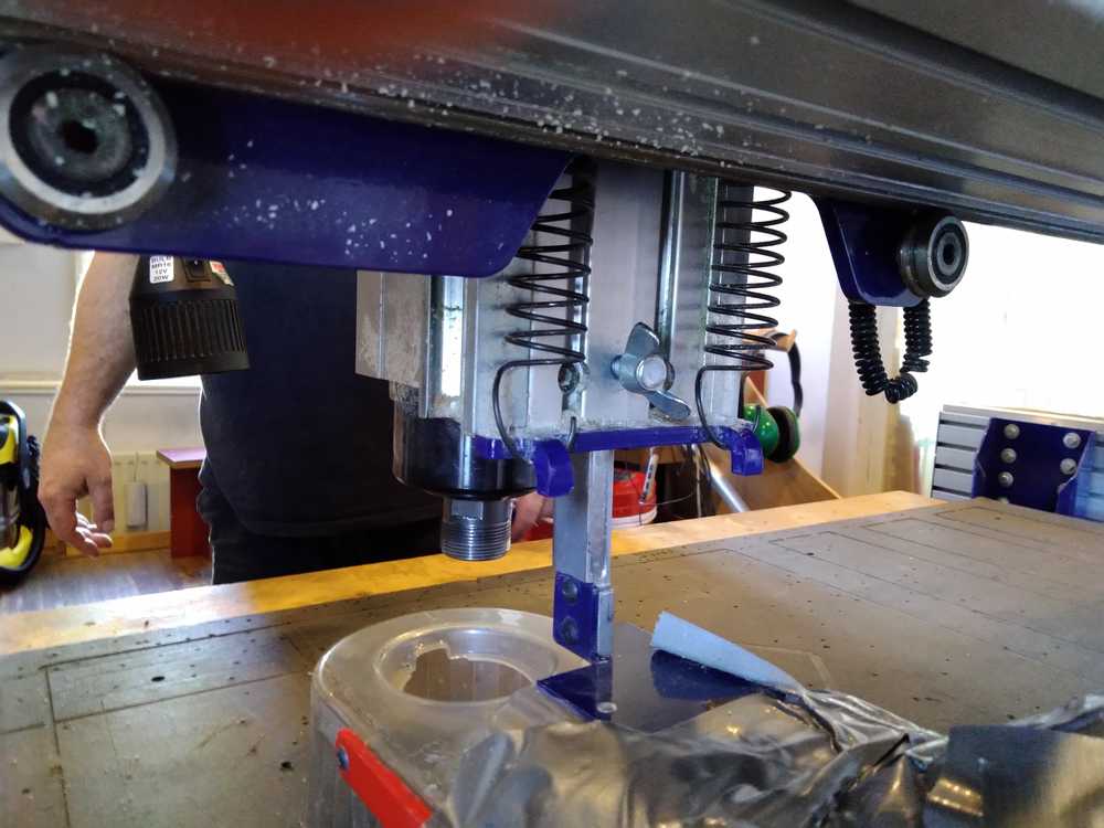
Changing the milling bit.
- Pull the bridge towards you.
- Lower the skirt to get to the spindle. Turn loose the wing nut.
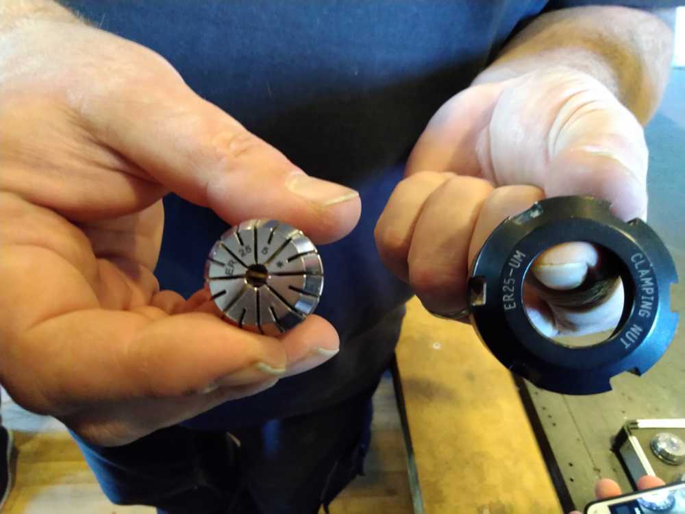
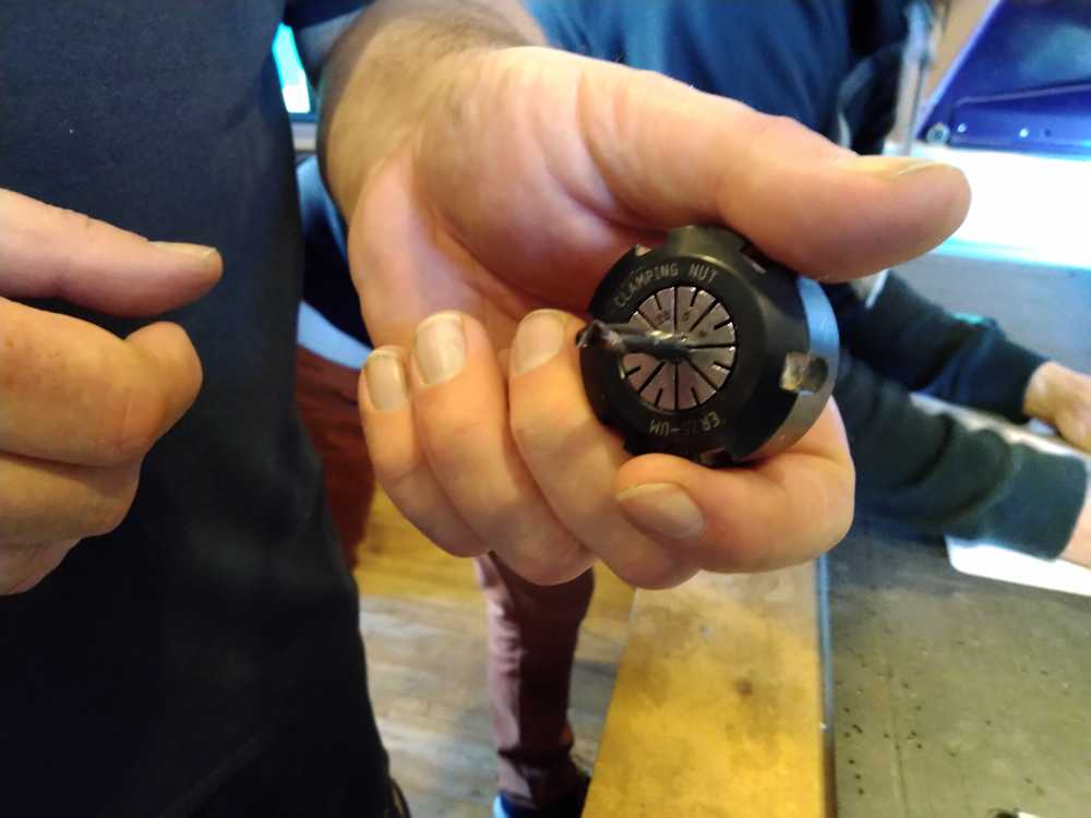
3. Unscrew the collet from the spindle by turning loose the ring.
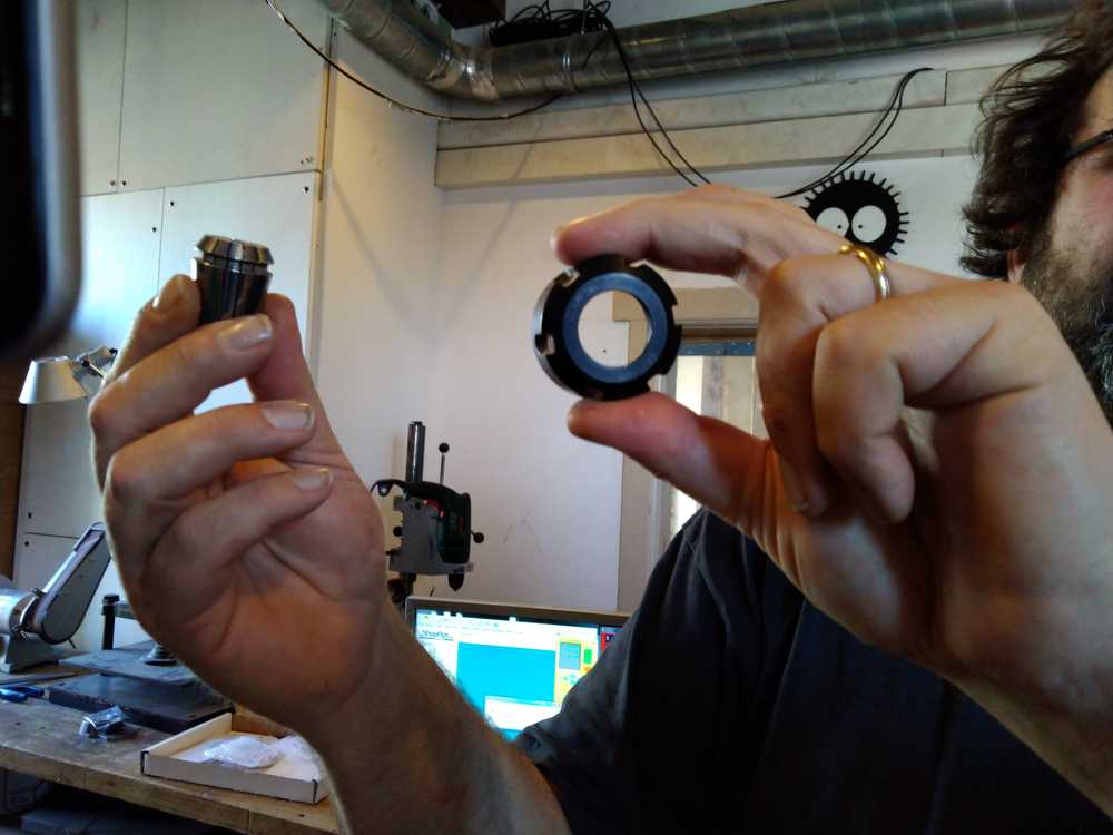
Collet left. Ring right.
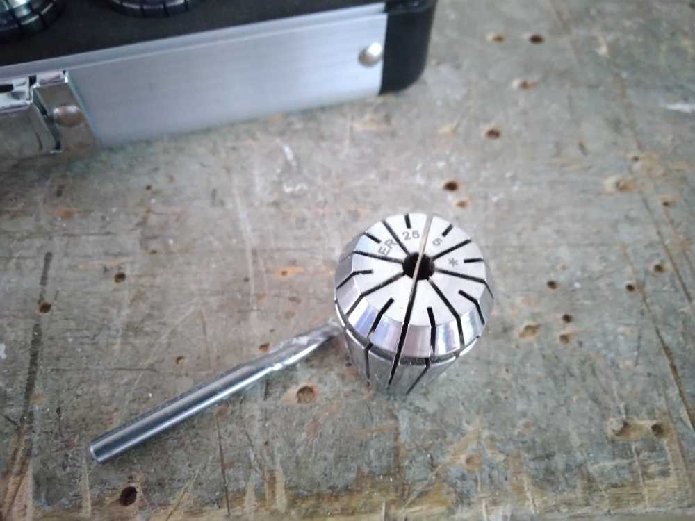
4. Pick the right size collet. The collet must have the same measure unit as the drill. A 5 mm drill needs a 5 mm collet. There are two numbers written on the collet. The ER- number refers to the ring. In the picture you see a corresponding ER-25 number on both the collet and the ring. The second number on the collet is the measurement of the diameter for fitting the drill.
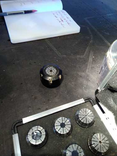
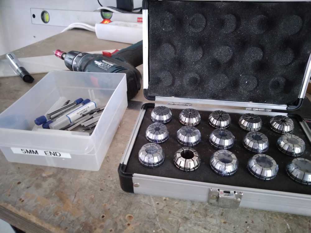
Location of the collets.
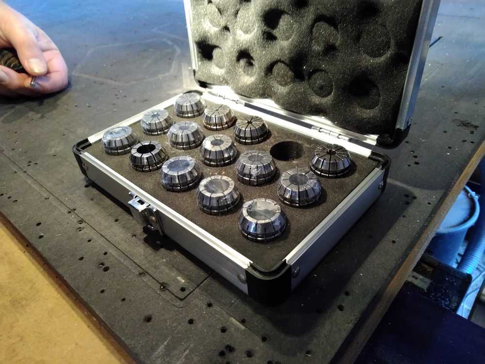
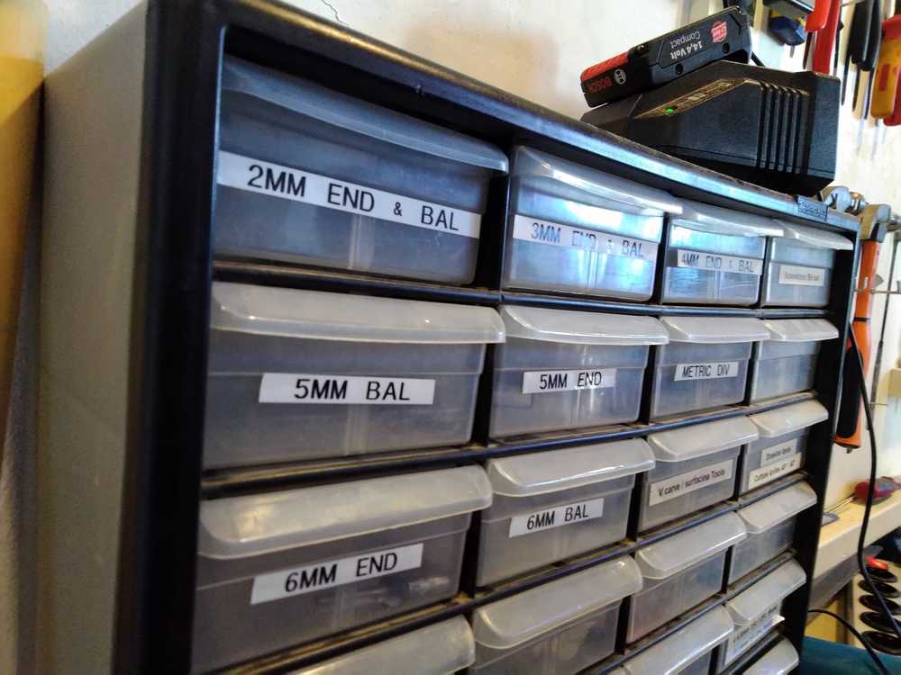
5. Pick the right size drill that you want. We have equimpent for the CNC in both metric and imperial measuring units. Only use metric tools. These are in the top 3 rows of the cabinet.
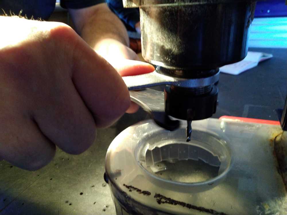
The drill and the collet will fit tightly together. If they don’t, you don’t have the right combination of drill and collet.
 6. Drill, collet, ring: order of assembly.
In: first put the collet in the ring, then put the bit in the collet. Be aware of this. In any other order the drill bit will be wbbly in its casing. But you won’t notice until it breaks during the milling process.
Out: First take out the bit of the collet. Then take out the collet of the ring.
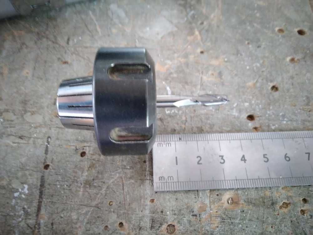
Also note the length of the drill. And then specifically the length sticking out of of the collet. The most common drill bit we have are about 40mm long. But they have to fit in the collet, so the part sticking out is about 25mm. The length of the drill limits the depth you can cut. If you cut deeper than the length of the drill, the collet and ring will hit your stock material. With soft material, the material will be damaged. With hard material the collet/ring/drillhead will be damaged. If you need to cut deeper than 25mm, there are drills with a longer size. We have drills with a length of a 100mm, for instance.
In: First put the collet in the ring.
Then put the drill in the collet.
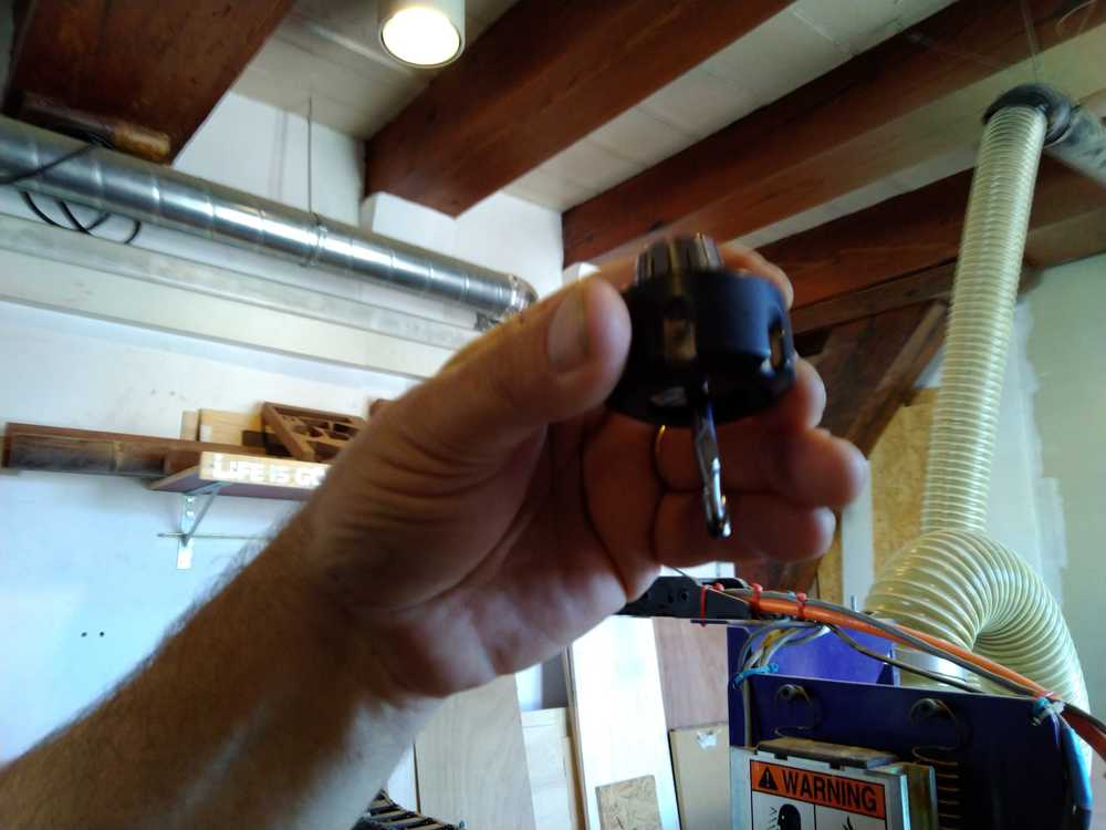
7. Use two fasteners to screw tight the ring.
The key to turn on the spindle is connected to the fasteners. This way you’ll never accidentaly try to screw the spindle while it is moving.
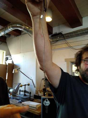
Key is attached to the fasteners.
The fasteners are kept here.
8. Put back the skirt.
9. Screw the skirt fast with the wingnut.
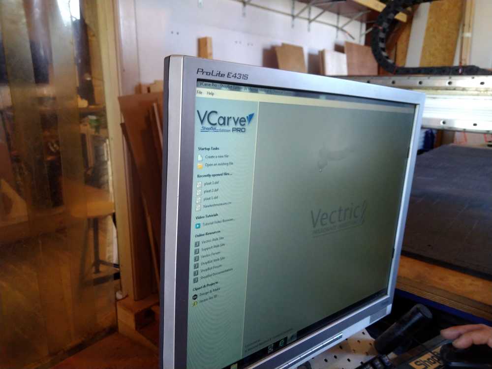
Software
We use two types of software. The Shopbot software to operate the machine. And V Carve Pro. The primary function of V-Carve is to turn your design files into G-code. But we use it for a lot more. We define the dimensions of the stock material in it. And you can use it to calculate your toolpaths. Although there are also other software programs you can use to do that. You can even use V-Carve to make an entire design. This is what we did for the group assignment.
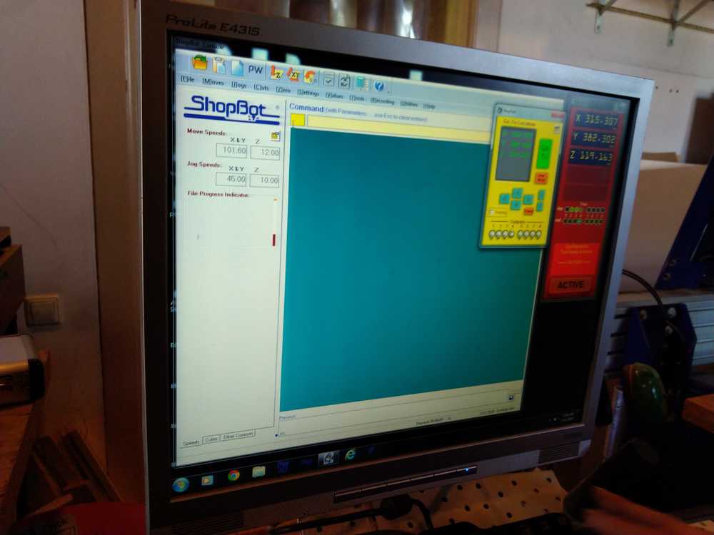
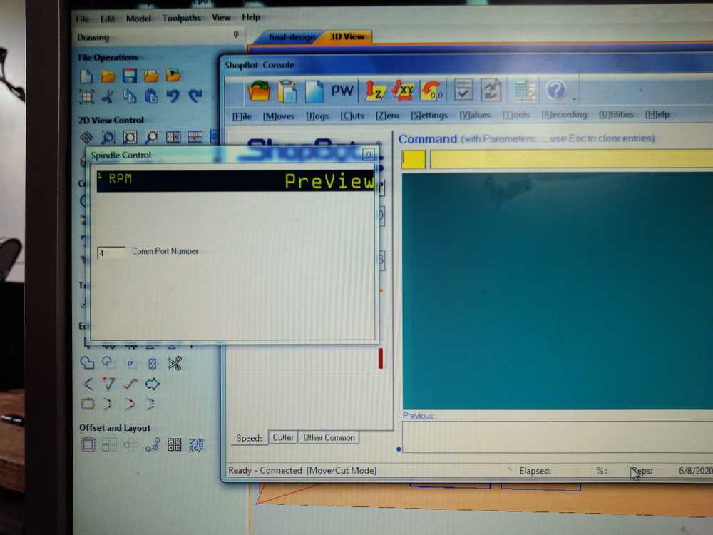
First we open the Shopbot software to be able to move the drill head.
Be aware that the machine does not know when to stop. Setting the wrong axes will make the machine want to run off the rails, or drill through the sacraficial layer into the bed.
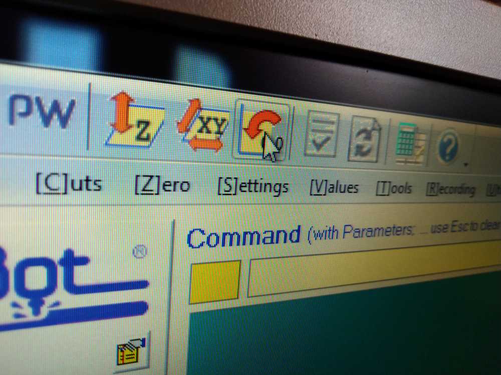
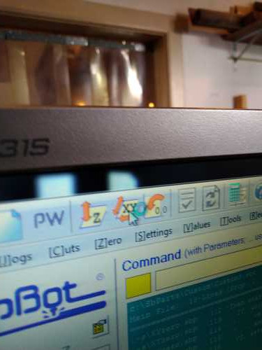
Shopbot software:
1. Open the software by clicking the icon at the bottom of the screen.
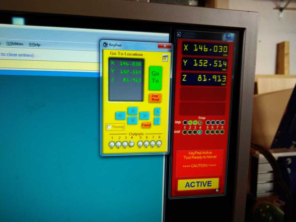
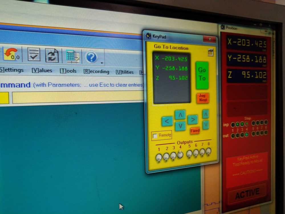
2. The movement of the machine is done by keyboard. Press K to open the panel. The x-axis is operated by the up/down arrows. The Y-axis is operated by the left/right arrows. The Z-axis is operated bt the up/down page keys.
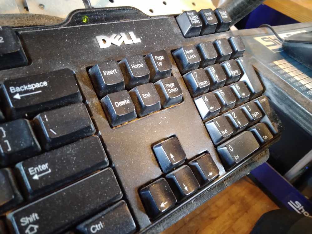
Machine’s axes is operated by the keyboard.
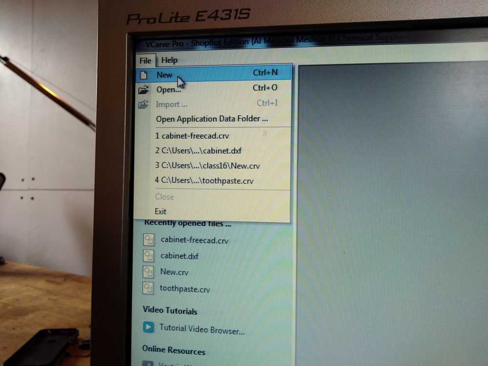
V Carve Pro:
1. Open the program with an icon at the bottom of the screen.
2. Open a design file: project-files > fab2020 > yourname.
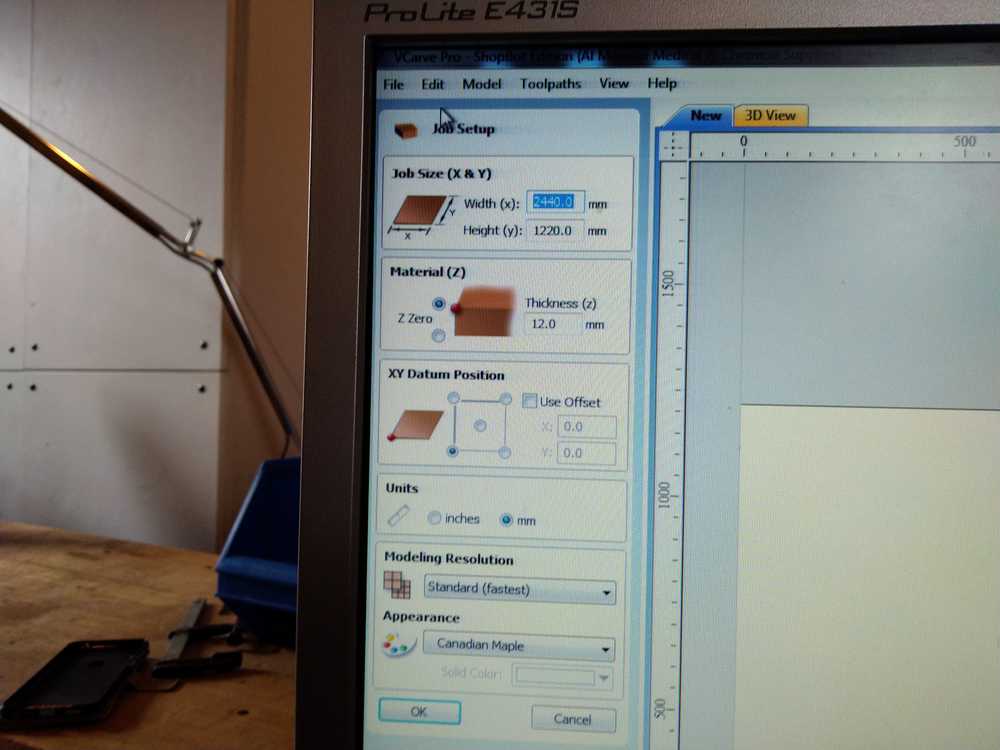
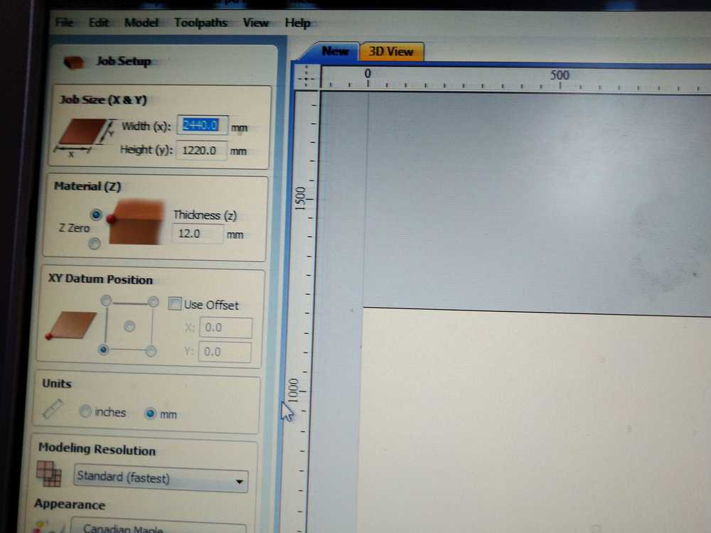
3. Go to job setup. Here you determine the constraints of your job.
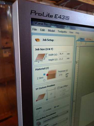
- Job size: the outer dimensions of your stock material.
- Material (Z): the tickness of your material.
- Determine the origin for the zero of the Z-axis. Choose top, left.
- XY datum position: Determine the origin of your stock material. Default: left lower space. This corresponds to the bed of the machine from when you are standing in front of the X-axis. That is, along the length of the bed with your back to the window.
& you can choose to add an offset.
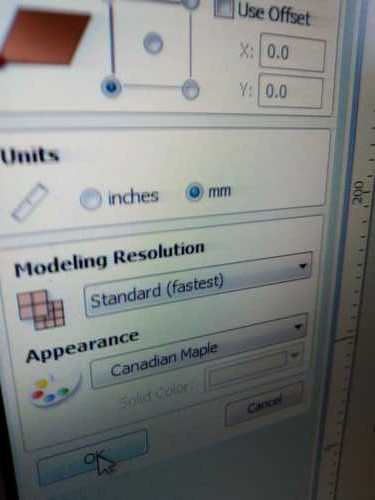
- Units: determine which units you are using.
- Use standard modelling resolution.
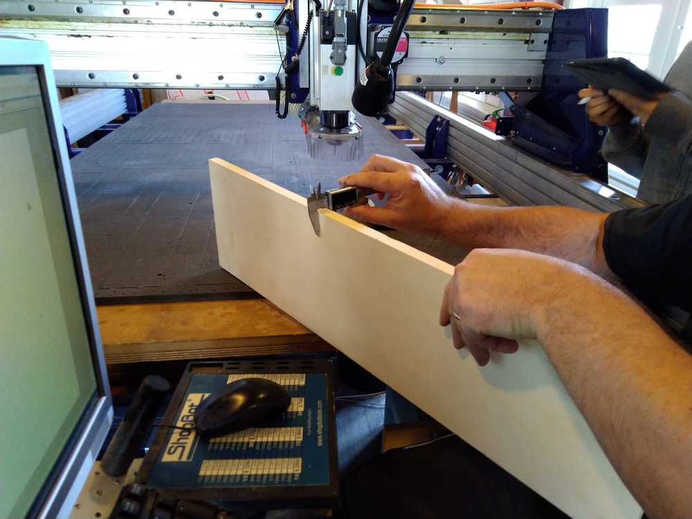
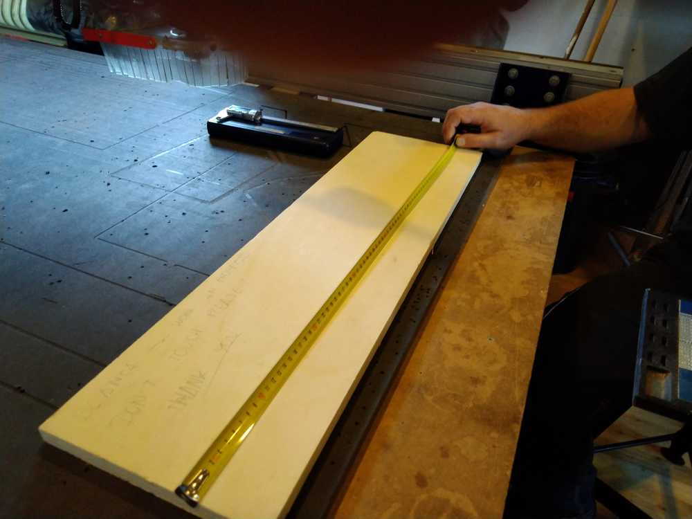
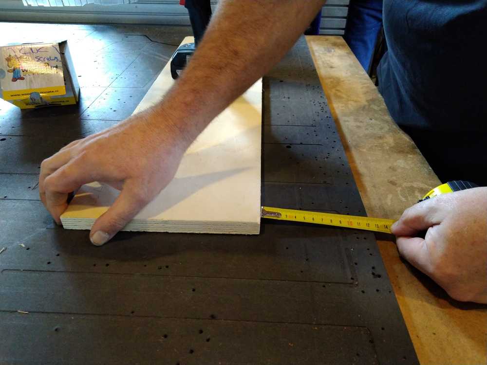
4. Measure your stock to put in the right thickness, length and width. Do not trust the measurements the wood supplier says it has.
5. Toolpaths Material:
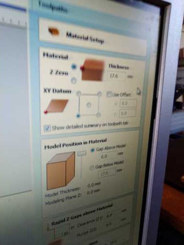
- Fill in the thickness of the material.
- Set Z-axis zero to upper-left.
- Set XY datum to lower left. The view on the machine bed is you standing along the X-axis, the origin is then on your left hand.
- Offset: yes or no.
- Select: show detailed summary on toolpath tab.
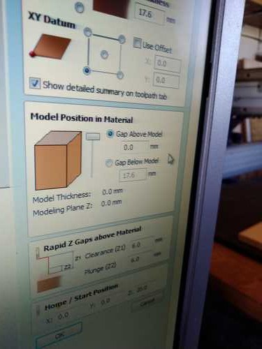
6. Toolpaths: model position in material
- Gap above model = 0.
- Rapid Z-gaps above material 6 mm (how much the head will move above the material between drilling jobs).
- Home start position set to 00.
Making a model
You can skip this step if you import a model from another program like FreeCad.
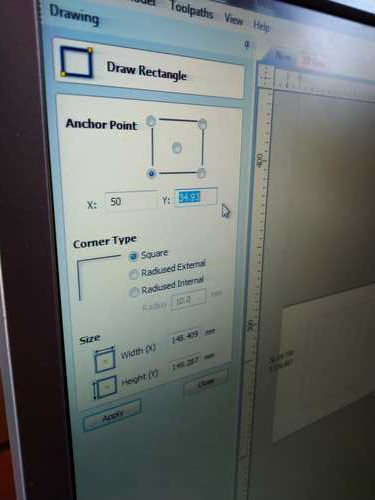
1. Draw a rectangle to determine your workfield.
- determine anchor point.
- determine corner type.
- determine size.
2. Make you model.
- Leave a place for screws.
- Leave space in between for the drill to operate.
Then you’ll get something like this.
3. Set your milling bit (for instance 5 mm).
- Determine spindle speed (default 14.000 rpm).
- feed rate (how fast the bridge moves: default 80 mm/sec).
- plunge rate (how fast the drill will go down: default 20mm/sec).
4. Generate toolpaths. You can find the toolpaths panel on the right side of the screen.
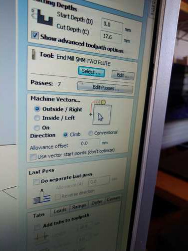
5. - Decide whether you want to mill outside the line or inside the line. Or on the line. Inside the line will make the material smaller.
- The number of passes is generated automatically.
- Choose climb or conventional: conventional for roughing, climb for finishing.
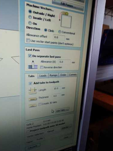
- Last pass: select separate last pass. It will remove uneven cuts.
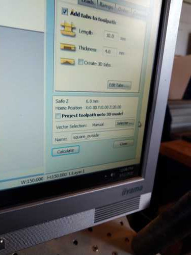
- Add tabs to toolpath. You must add tabs otherwise your material will fly loose when drilling is nearly done.
- Don’t add tabs in corners as you will not be able to get them out.
6. Settings:
- starting depth = 0.
- cut depth = thickness of the material. (17.6 mm in our example).
7. Cutting parameters:
- pass depth (depth in 1 run of the mill). Default is 50% of the drill bit.
- Stepover: default is 50%.
- spindle speed: default is 14.000 rpm.
- Feed rate: (how fast the bridge moves over x-y axes). Default 80 mm/sec.
8. Cut:
- profile: cut through the material.
- pocket: edging: carve some of the material away.
9. - Do not use larger area clearance tool.
- With pocket: choose raster.
- Choose climb or conventional.
- Do not select ramp / vector selection.
10. Add fillets if you need sharp corners. The drill can’t reach all the way in to make 90 degree corners.
11. Decide how many runs you need. If all is done with the same type drill bit you can do all objects in one run. If you need to change drill bits in between. You can select only a few objects and have them run first.
12. Select all toolpaths.
13. Preview: simulates the path of the drill.
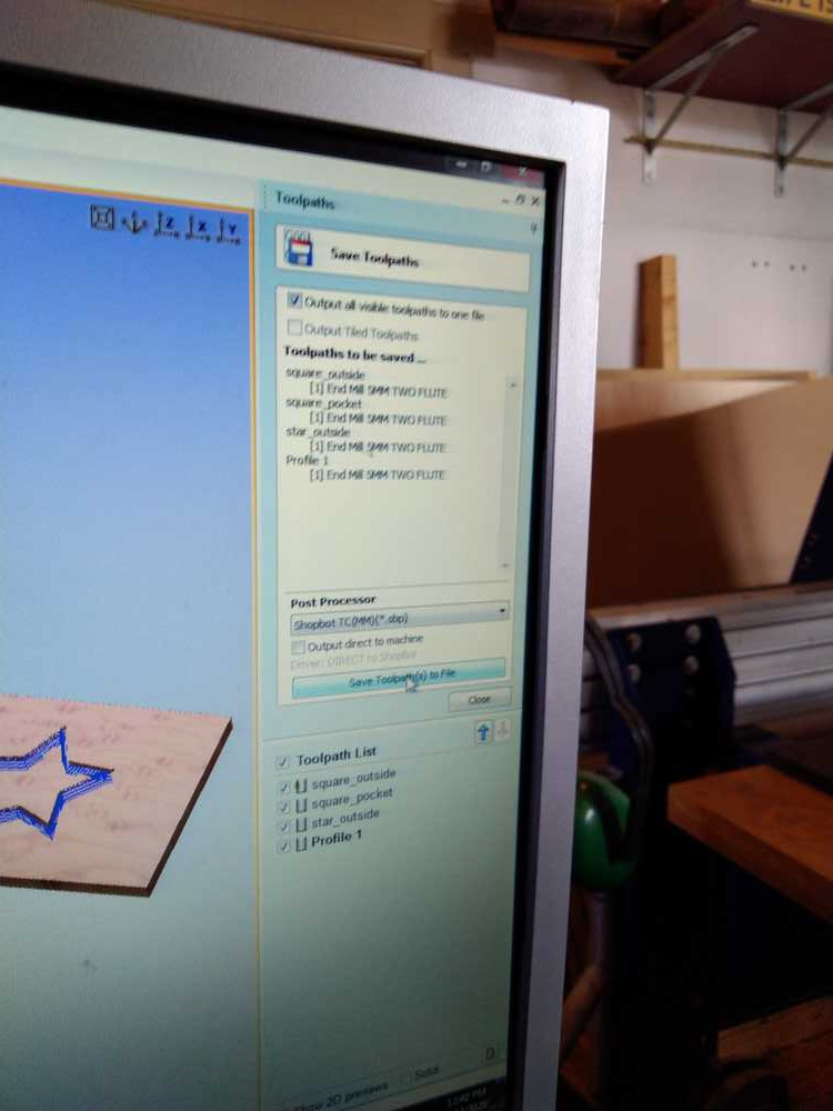
14. save all toolpaths.
15. Calculate: calculate g-code.
16. Save the file twice!
- One saves the g-code file.
Save in one file? Yes.
Save in Shopbot format? Yes.
It will tell you what mill it will be using. Confirm is correct.
- Two saves the file as a V-Carve project.
Importing designs You can import designs from for instance FreeCad or Inkscape. Import as .DXF or .STL.
Achoring your stock to the machine bed
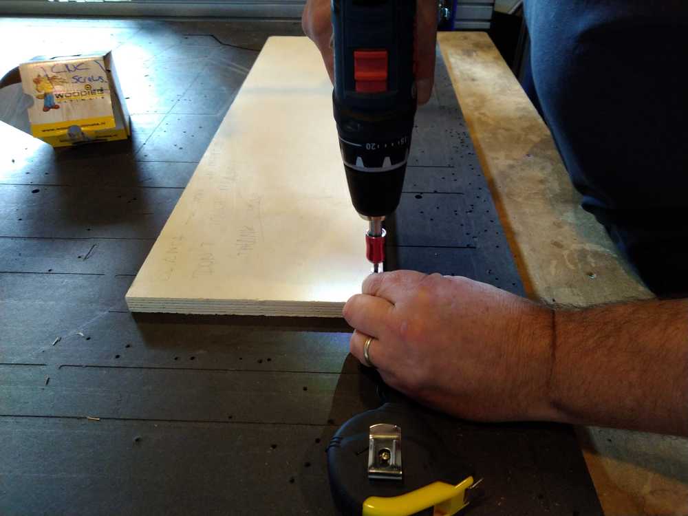
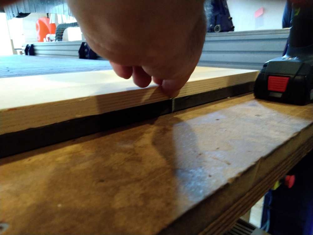
Fasten your stock to the sacraficial layer with woody screws. Make sure the path of the drill does not go over the screws. It’ll give sparks and possibly a fire. You can draw your screws in your design. You can select them in the software and have the mill drill superfacial markings on the board (before it is fastned to the bed). You then screw the board where the markers were placed. Then remove the markers in your design to make sure the mill won’t hit those places again.
- The drill is in the closet in the back of the room.
- Use woodies with a torc and use the right bit.
- Measure the length of the screw, don’t drill through the sacrafical layer. Not only bad for the bed but also will lift up your stock and misalign the Z-axis. Don’t make the screws too short, either.
- Screw about every 30 cm. With big slabs of stock add screws in the middle as well.
- Make sure the stock is straight everywhere.
Operating the machine
- Put in the bit. Even when the right size bit is already in. Remove and re-insert to make sure.
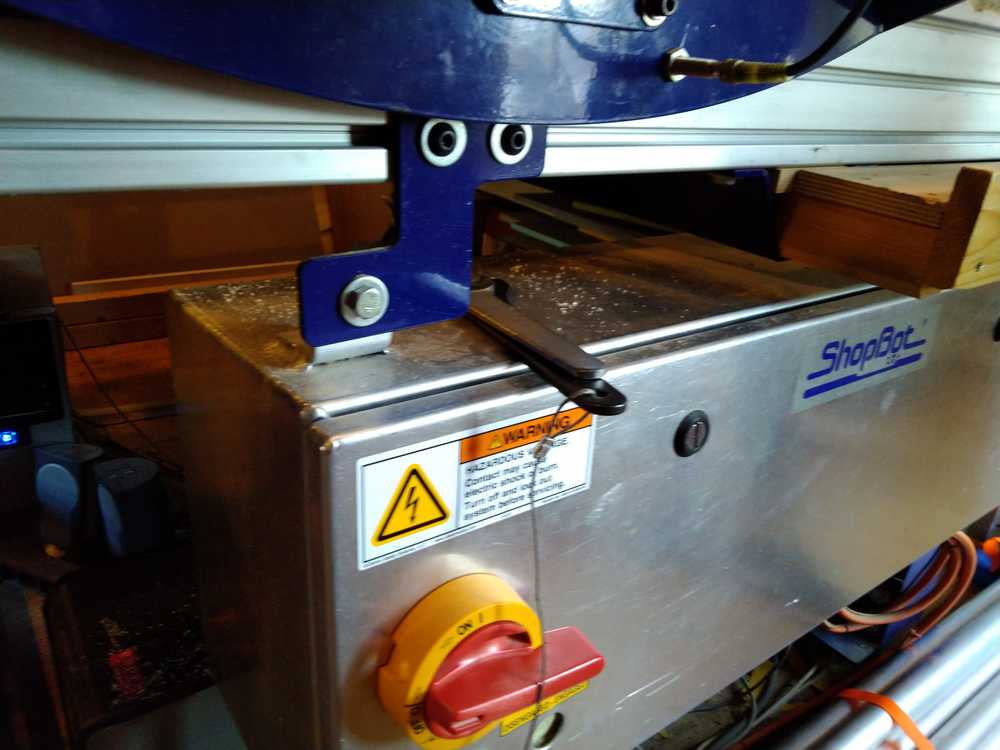
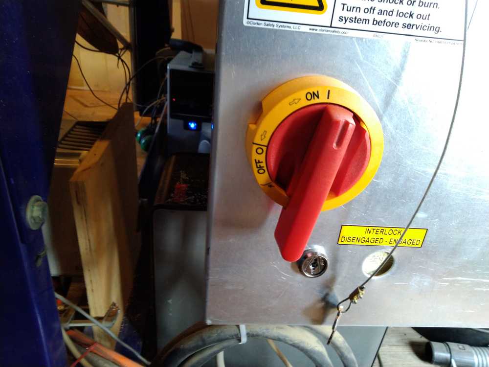
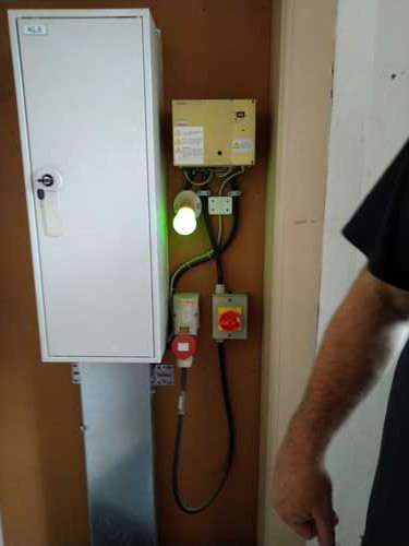
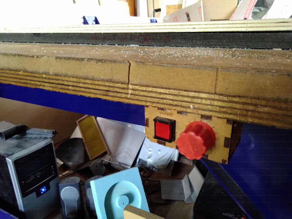
- Put on the machine with the red switch.
Shopbot software
Zeroing X-Y-Z axes.
1. Press the x/y icon (or the 0/0 icon) to have the header move to the machine’s origin.
2. The machine has a limit switch otherwise it does not know when to stop.
3. Move the header manually to the origin of your stock. Press K to open a yellow panel and move over the x-y axes with arrows .
4. Mark down the values of your X-Y-axes, as you may need them later. (Just as with the small milling machine.)
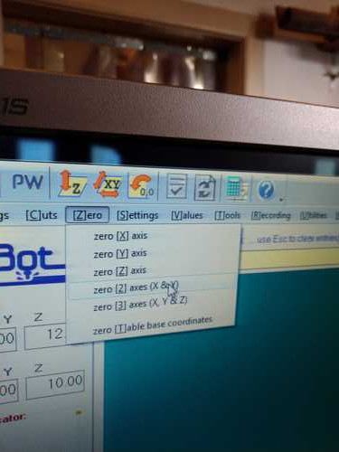
5. Zero the X-Y axis on the top of your stock. This will set the values to zero on the top of your stock material.
This is done with the Zero dropdown menu at the top of the software window. Choose Zero axes (X&Y).
Remember: in the software select the lower left side for origin. This corresponds to facing the machine bed from the X-axis with the on/off switch on your left hand.
6. Z-axis: when you move the Z-axis with page up/down it will move 1 cm per press.
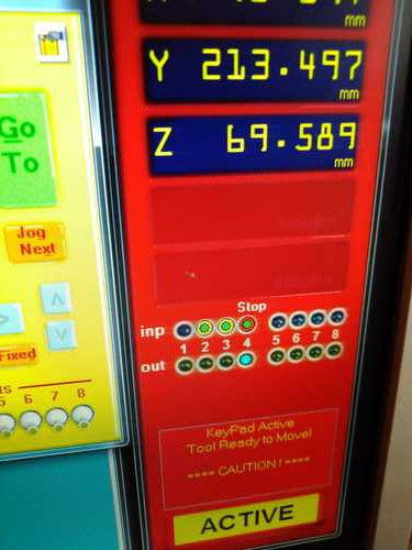
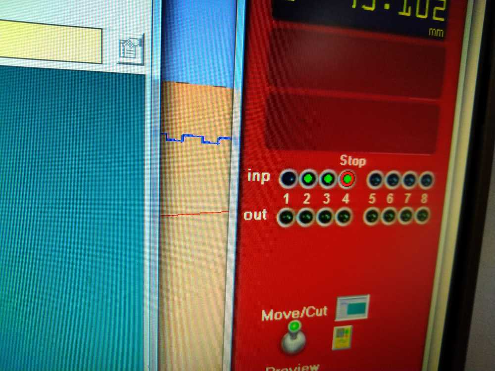
7. Zero the Z-axis: Get the iron plate from the header. This is connected with an electrical wire to the machine. Touch the plate to the drill and watch the first circle after INP in the red panel. A green light indicates the drill sees the metal plate.
Place it under the drill. Remove all dust.
The drill will go down and automatically stop when it reaches the plate.
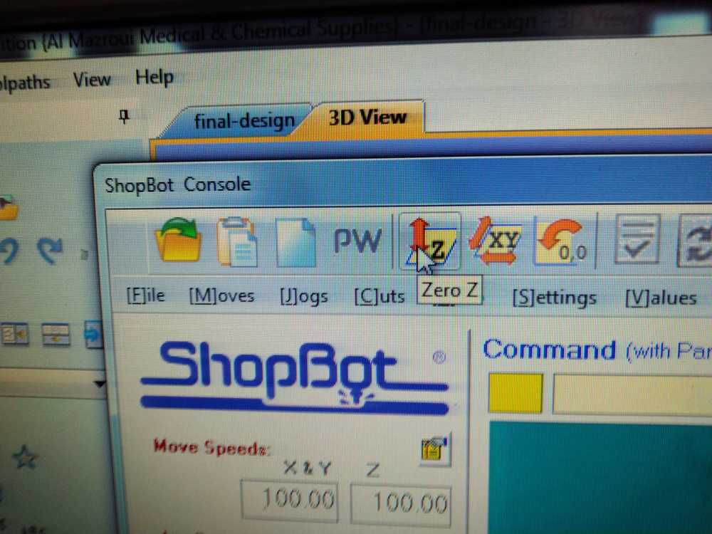
Click the ICON Z. not the dropdown menu. Not the 0.0. But the Z icon.
Check again if the drill is above the plate.
Press okay.
8. The drill will move down on its own, stop at the plate and stop. It has now zero’d itself. You need not click any confirm button after that.
9. Press 'page up to move the Z-axis up (or use the arrows in the yellow software panel). Remove the metal plate.
10. The Z-axis is now zero’d. The 3.07 mm of the metal plate is extracted automatically.
Dry run
You can choose to do a dry run first. Having the drill follow its path without actually cutting. This way you can check if the drill is taking the path you expect. You do this by Zeroing the Z-axis much higher than the actual stock. Take a box that is higer than your stock. Zero the Z-axis. Run the job in the air to see if it does what you expect.
Running the job
You have now:
1. fastened your stock material to the bed.
2. Checked the drill.
3. Zero’d the X Y and Z axes.
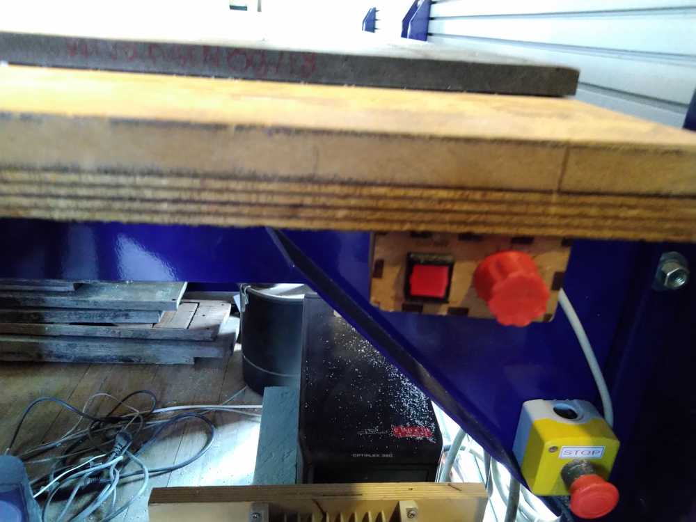
To stop the machine:
1. Emergency stop. This will kill electricity to the machine.
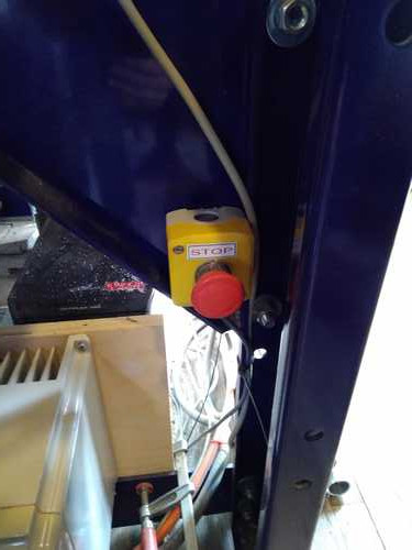
2. You can pause the job by pressing the spacebar.
Start the job
1. Put on the dust collector in the back of the lab.
2. Put on the dus collector on the machine. The red button puts it on. The turn button increases/decreases power.
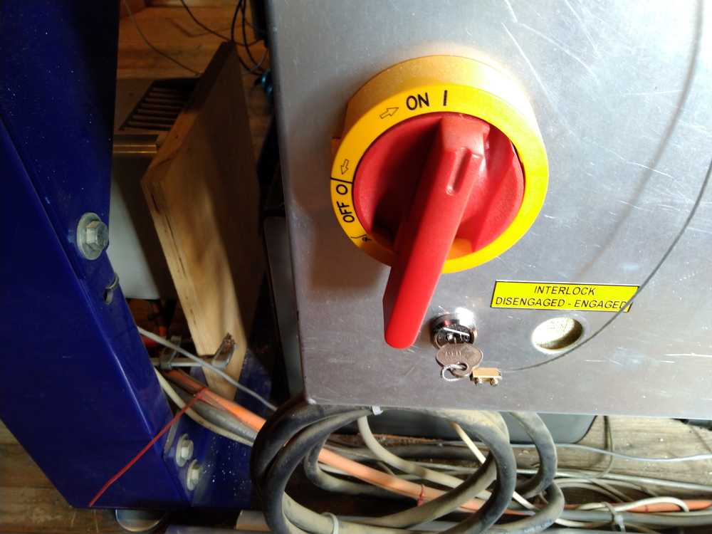
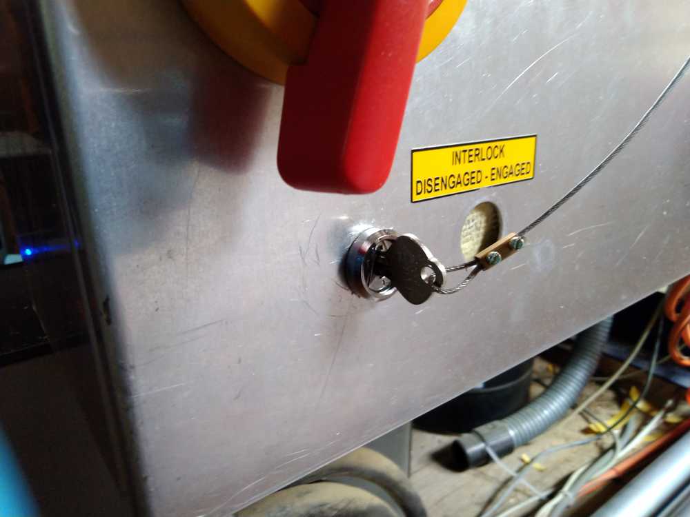
3. Turn on the spindle by locking the key and turning it.
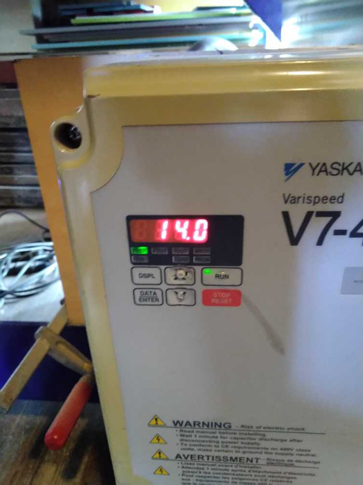
4. Put the spindle on the speed specified in your software. Do this manually with the up/down buttons on the little spindle panel.
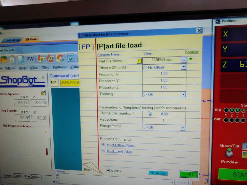
5. Import your design file.

6. For at least the first minute after the job has started, keep your hand on the space bar to stop if necessary.
7. Click run.
The machine is milling.
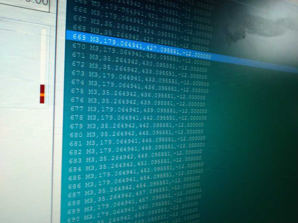
You can follow the proceedings of the G-code on the monitor.
Shutting down the machine
- Turn off spindle by turning the key.
- Turn of dust collector locally.
- Move header to machine origin.
- Turn off machine with red switch.
- Turn of the dust collector at the back of the room.
- Unscrew your stock from the bed.
- Vacuum clean the bed.
- Use sanding paper to even sacraficial layer where screws were used.
- Vacuum clean bed again.
- Vacuum clean floor around the machine.
- Remove all your left-over stock material from the machine room. Or put neatly away.
Overview steps CNC machine
Emergency break
- Stop the machine.
- Lift the Z-axis.
- Go to dust collector and thoroughly inspect the bag for hot wood.
- When you’ve seen sparks, always remove the dust bag.
- Do not resume milling afterwards. You will be stressed and that will impair your ability to operate the machine safely.
Always remember:
- Never touch the machine when turned on.
- Spindle keeps on moving even if you stop the machine. This results in heated wood dust and chips.
Preparation
1. Get into Zen mode.
2. Check your hair. Put long hair in a bun.
3. Check your clothing. No cords dangling from your hoody. No scarf around your neck. No loose shoe laces. No loose cords, belts , strings, etc.
4. Put on safety protection clothing: safety glasses. ear plugs, gloves, shoes
5. clean the bed of the machine.
6. clean around the machine.
Changing the milling bit
- Pull the bridge towards you.
- Lower the skirt to get to the spindle. Turn loose the wing nut.
- Unscrew the collet from the spindle by turning loose the ring.
- Pick the same size collet and drill. Only use metric tools.
- Ring, collet, drill: order of assembly.
In: first put the collet in the ring, then put the bit in the collet. Be aware of this. In any other order the drill bit will be wbbly in its casing. But you won’t notice until it breaks during the milling process.
Out: First take out the drill bit of the collet, then the collet out of the ring. When attached to the drill head do the following: loosen the ring a little bit while holding the drill. When sufficiently loose take out the drill. Then unscrew ring further and take collet and ring of the drillhead. - Use two fasteners to screw tight the ring.
- Put back the skirt.
- Screw the skirt fast with the wingnut.
Anchoring your stock to the machine bed
- Fasten your stock to the sacraficial layer with woody screws.
- Make sure the path of the drill does not go over the screws.
- Use woodies with a torc and use the right bit.
- Measure the length of the screw, don’t drill through the sacrafical layer. Don’t make the screws too short, either.
- Screw about every 30 cm. With big slabs of stock add screws in the middle as well.
- Make sure the stock is straight everywhere.
Shopbot software
- Open the software by clicking the icon at the bottom of the screen.
- The movement of the machine is done by keyboard. Press
Kto open the panel. The x-axis is operated by theup/down arrows. The Y-axis is operated by theleft/right arrows. The Z-axis is operated bt theup/down pagekeys.
Zeroing X/Y axis
1. Press the x/y icon (or the 0/0 icon) to have the header move to the machine’s origin.
2. Move the header manually to the origin of your stock. Press K to open a yellow panel and move over the x-y axes with arrows .
3. Zero the X-Y axis on the top of your stock with Zero dropdown menu at the top of the software window. Choose Zero axes (X&Y).
4. Mark down the values of your X-Y-axes, as you may need them later. (Just as with the small milling machine.)
Zeroing Z-axis
1. Place the plate steady under the drill. Don’t touch it while it is zeroing.
2. Touch the drill with the plate and check if the green button lights up.
3. Click the ICON Z. not the dropdown menu. Not the 0.0. But the Z icon.
4. The Z-axis will now zero itself.
5. You don’t need to confirm the levelled Z. This is the entire process.
6. 5. Manually make the Z go up.
7. remove the plate.
Group assignment
A full description of the group assignment can be found on our communual page.
Description of the group assignment
Goal: test runout, alignment, speeds, feeds, and toolpaths for your machine.
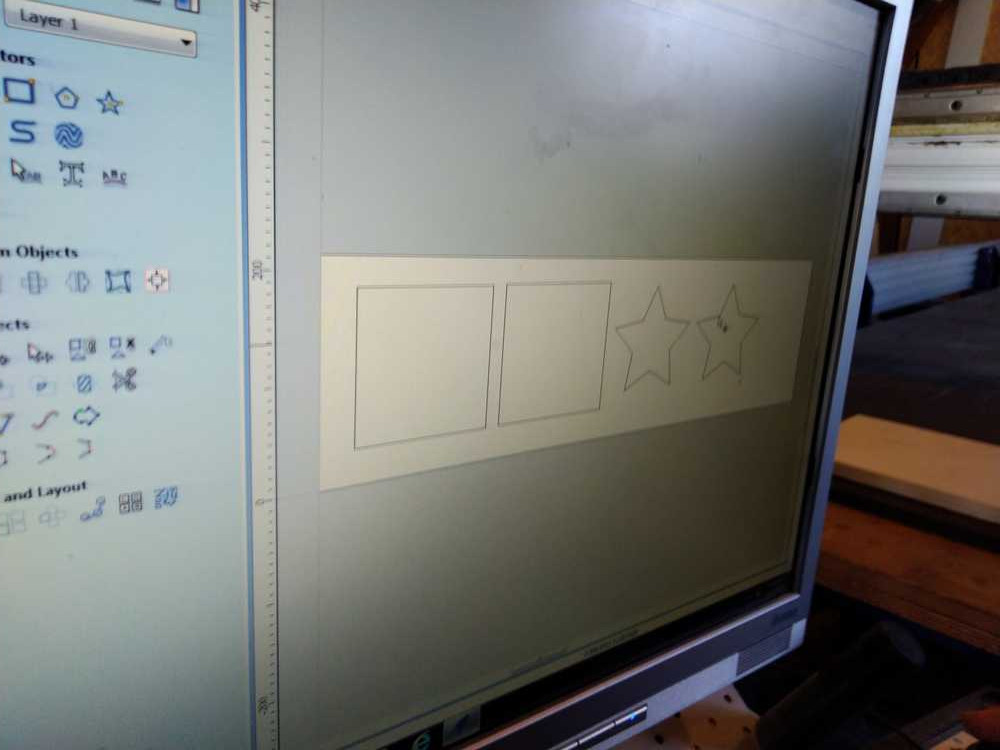
We made a design file together during the explanation of the CNC machine.
The design file is made in V Carve pro.
We use a piece of wood with a thickness specification of 18 mm. But never trust your wood supplier. We measure the thickness. It varies between 17.5 - 17.7 mm. We choose to use cut depth 17.6. This is the thickness of the cut depth.
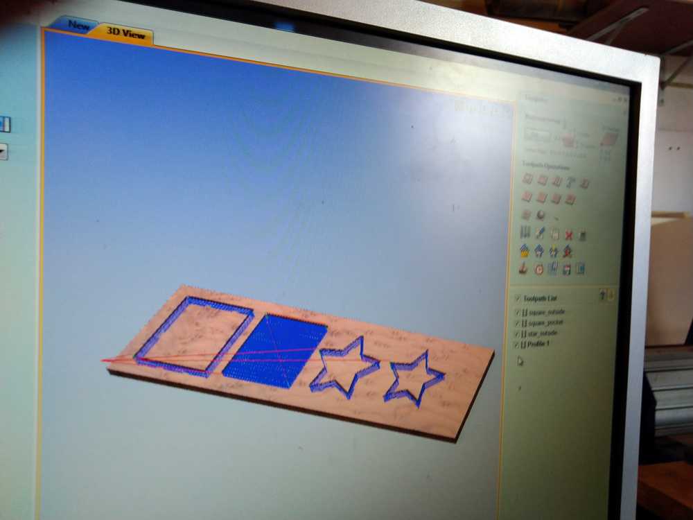
We make two squares of 150 x 150 mm
And two stars
Square 1: outside line
Square 2: inside line & pocket
Star 1: outside line + pocket
Start 2 inside line
Square 1: Outside line
Cut should be 150.00 mm. The actual measurement is 151.15 on one side of the square and 150.78 on the other side of the square
Inside cut should be 150.00 mm on both side of the square. The actual measurement is 149.57 on one side of the square. The other side 150.15
Measure run out:
Runout: runout is the actual width of the path. A drill will be x mm but the path it cuts will be bigger because it operates slightly wobbly.
Test how big the actual path is:
We have a 5 mm drill bit. So the cutout from both sides should be 2x5 = 10mm. We measured in the horizontal a 10.03 gap. And vertical 9.66 mm. This can’t be right because the 5 mm drill should at least remove 10 mm. But you can see that the inner square can not be entirely pressed to the side of the outer square. So the impossible measurement of 9.66 mm is due to this ‘unscientific’ method.
The inside line square will not fit into the outside line square. We forgot to put dogbones on the corners. It would have fitted if we had applied them. The inner square when placed vertically in the middle of the outer square does fit.
For the pocket square we used a last pass to make a straight line. A pocket is made by sending drill back and forth. Because it is round it will not make a straight line but will have many bites in it. The last pass should make a straight line. This worked really good.
Star 1: outside line + pocket
Start 2 inside line.
The inside line star won’t fit into the outside line star. We did put dogbones on the points if the star. But we forgot to put dogbones on the corners of the star. Therefore there is not enough room for the press fit.
Test speeds
This test is done by milling at different speeds and look at the result. You do not want to go to slow because that will take much time. Too fast will not result in a pretty cut.
Test toolpaths
The toolpath is the traveling path of the machine. We tested the Pocket toolpath and the Profile Toolpath.
The Profile Toolpath will just mill the lines.
The Pocket Toolpath will take out the material in between the lines.
Check the Quality of the cut using different
Mills (sizes and flutes).
Move Speeds (how fast the bridge moves over the X-Y axes.)
Spindle speeds (rotation).
| move speed | drill speed | drill old/new | mm | flute | Z |
|---|---|---|---|---|---|
| 80 | 14.000 | old | 5 | 2 | 12 |
| 80 | 18.000 | old | 5 | 2 | 12 |
| 80 | 14.000 | new | 6 | 2 | 12 |
| 80 | 18.000 | new | 6 | 2 | 12 |
| 80 | 14.000 | new | 5 | 1 | 12 |
| 80 | 18.000 | new | 5 | 1 | 12 |
| 100 | 18.000 | new | 5 | 1 | 12 |
| 140 | 18.000 | new | 5 | 1 | 12 |
| 140 | 18.000 | new | 5 | 1 | 50 |
| 180 | 18.000 | new | 5 | 1 | 50 |
Conclusion:
Drill speed we don’t see much difference but 18000 is slightly better Old drill v new drill: New drill is much better. Move speed: the faster setting makes a less straight cut. Flute: The edges made by the 2 flute drill are less rough than the 1 flute drill.
What I learned from the group assignment
One thing I learned was the actual functions of the different settings. I now understand what move speed, drill speed and plunge speed are.
The 2 flute leaves a more precise cut than the 1 flute drill. This is different from our findings from the small milling machine where the 2-flute scored worse on every account.
The age of the drill is very important. It new drill is much better.
I did understand what a runout is and why it exists. But we could not really see it on our cutted boards.
The different type of toolpaths became really clear. I understand the pocket toolpath and will apply it in my individual assignment.
Another clear thing is to cut outside, inside or on the line. This makes a huge difference for where the stock is removed.
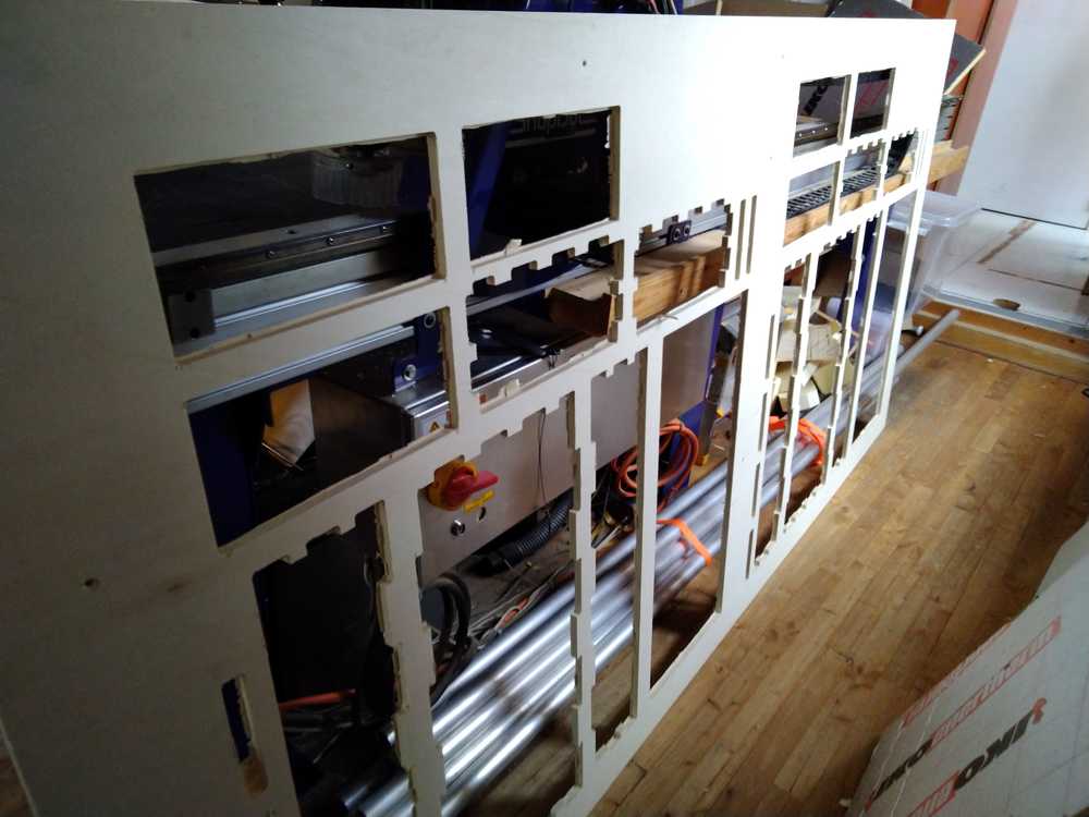
Individual assignment: Make something big
First I wanted to make a bed. But when I learned the dimensions of the wooden plate I realized the volume of the wood was not enough to make the bed.
Considering making a bed.
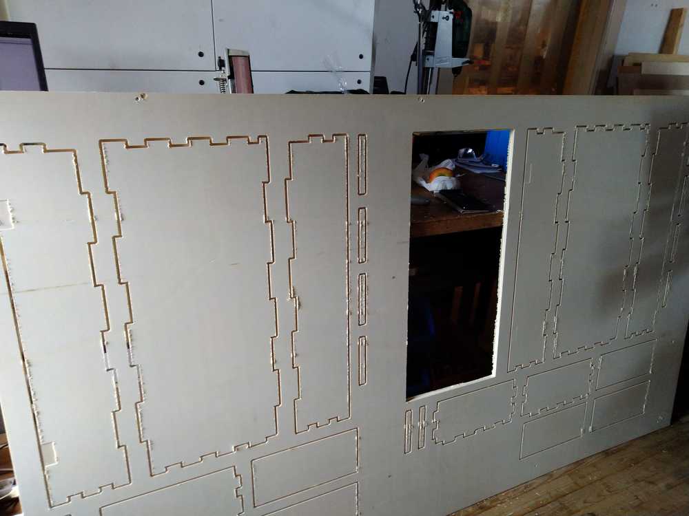
I then decided to make a kitchen cabinet. I have two racks to store my herbs but these are open. Over time this is not a good idea because the fumes from cooking tend to attach to the bottles and they become greasy over time. Therefore I decided to use this assignment to replace the racks with two closed-door cabinets.
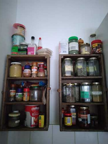
Kitchen racks to be replaced by closed-door cabinets.
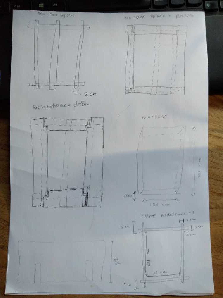
Design by hand
First I designed the cabinet by hand.
Measures of the space where the two cabinets must fit are 645mm width, 700mm length and 154mm depth.
I drew an overview of the cabinet.
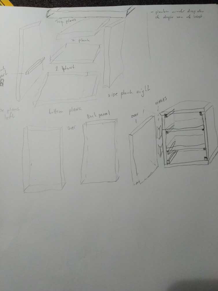
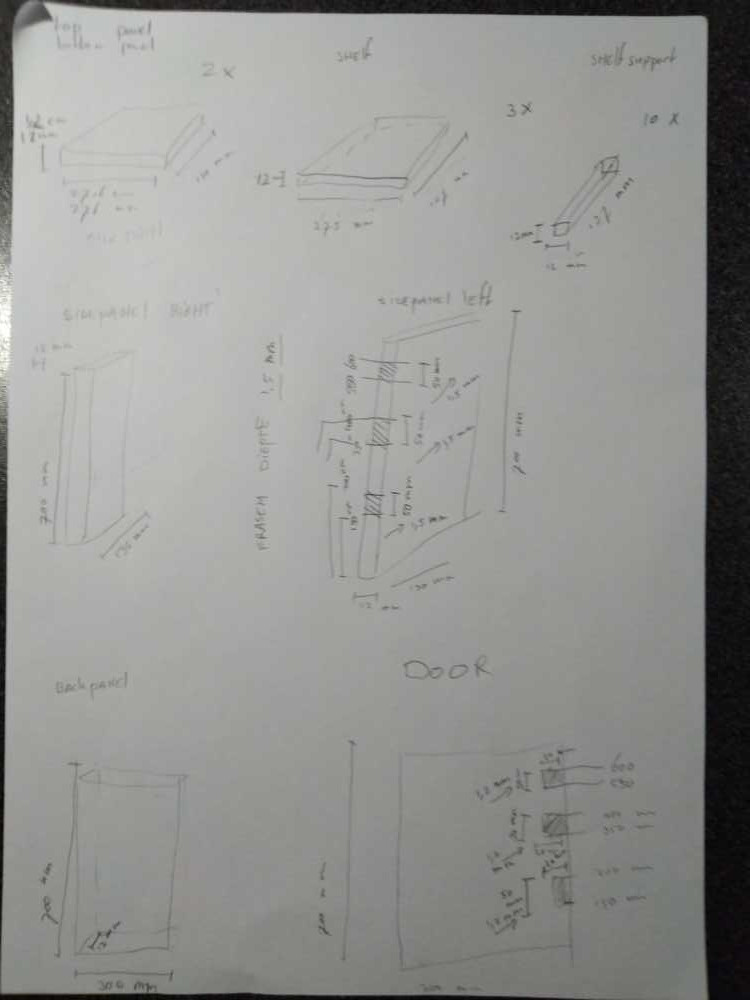
I drew each individual element and added the measurements.
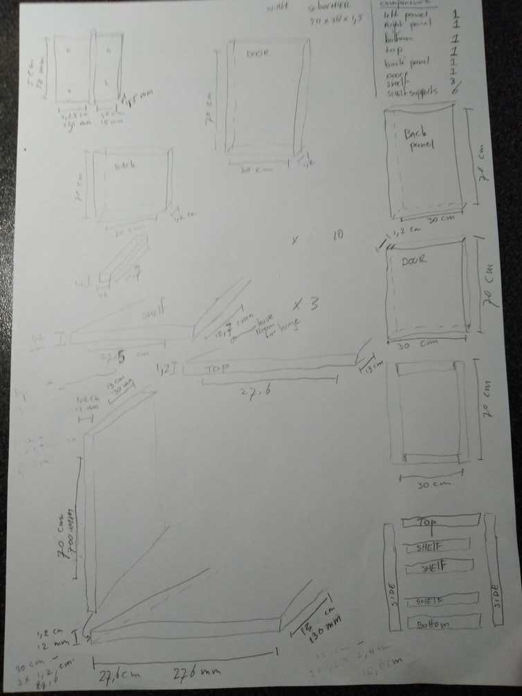
Some of the things I paid attention to: The width of the cabinet will be 300mm. The side panels fold over the top and bottom panel. That means the top and bottom panel must be 300mm minus the thickness of the material (2 x 12mm = 24mm) which amounts to 276mm.
The shelf width I made 1cm less wide than the top and bottom panel. I fear I will not be entirely accurate (I seldom am when it comes to measuring) so I leave some margin to make sure that the shelves will fit inside the cabinet.
The length of the shelves are not 130mm (which is the length of the cabinet as a whole) but 127mm. This leaves a little room to place them behind the hinge.
I’ll use little square supporting blocks to support the shelves.
The back panel and the door are the same size: 300mm width, 700mm height & 12mm thick.
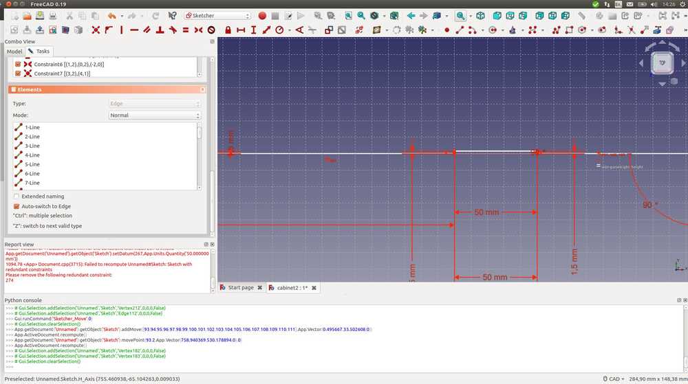
The third page of design is decicated to milling a pocket for the hinges. Both the left side panel and the door must have pockets for the hinges. I’ll put in 3 hinges placing them 150mm apart. The hinge is 50mm in length, 20mm in width and 1,5 mm thick. The depth of the pocket must therefore be 1,5 mm.
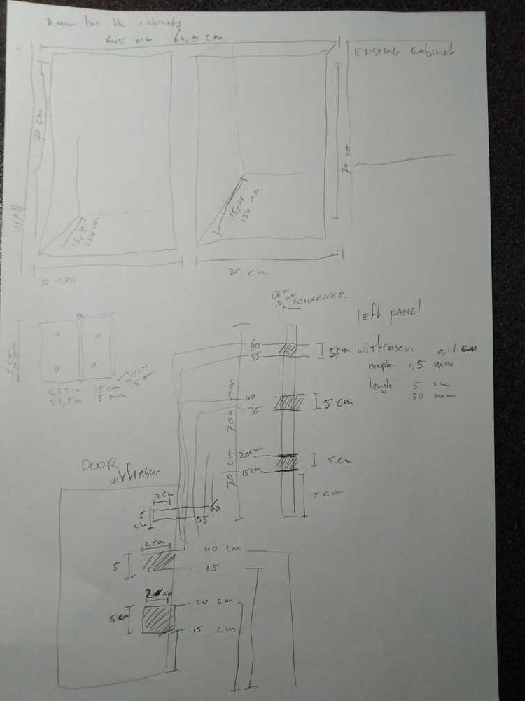
I then made a page with an overview of all the elements of the cabinet and the amount I need of each. I made the mistake of writing 1,2mm for the depth of the hinge in some places in the design. As I wrote this down I realized my mistake and adjusted it. The photo is from before the adjustment.
I’ll now will design all my cabinet elements in FreeCad. I think I will need to redraw them tomorrow in V-Carve. Because adding things like tabs at is probably better done in V-Carve.
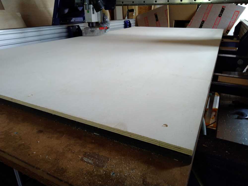
The size of the wooden stock material is 2440mm length, 1220mm width and 12mm thickness.
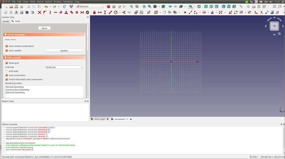
FreeCad
I wanted to adjust the grid size. The default grid size is to small to fit the stock material on. Unfortnately this turned out to be too difficult to be done within a reasonable amount of time. The path preferences > draft > grid and snapping > grid size gave some option like more lines per measuring unit. But none of it enlarged the grid itself.
Preferences > display > new document scale did not immediately result in a larger sketch grid either. When you then zoom in, the grid will extend all the way to the end of the X-Y arrows. But when you add an object, it goes small again. In the end FreeCad oscillates between showing and not showing the grid over the entire length of the canvas.
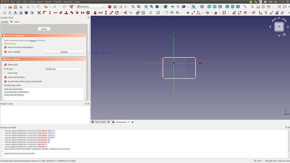
I used a lot of copying and moving. To copy: select object by drawing rectangle around it. CTRL C a line appears. Where you drop the line and mouse click, the copied object will me places. For moving it is similar using CTRL M.
Creating an indent in the left side panel for the hinge.
Specifying the pockets for the hinges on the door:
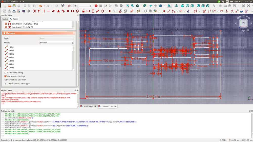
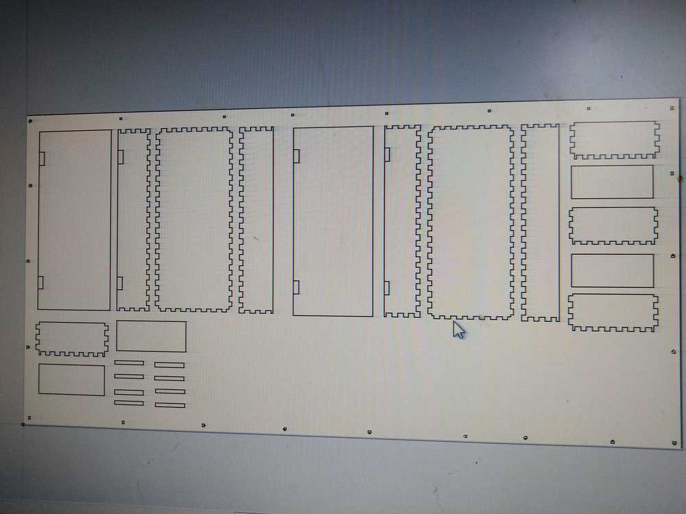
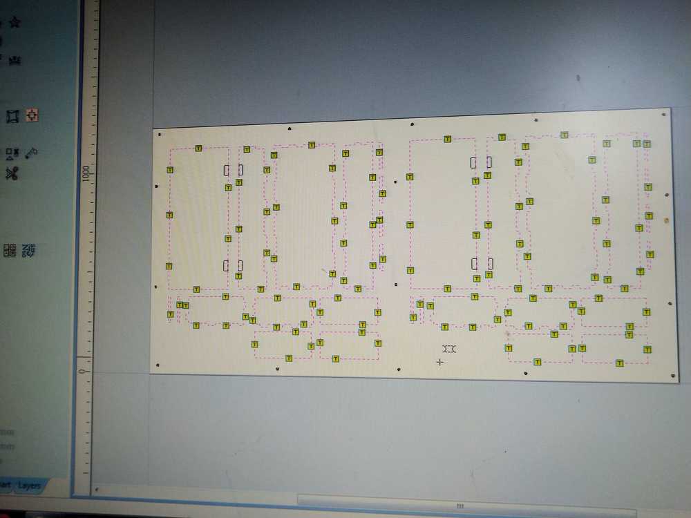
It took some shuffling around of the elements to get them all to fit. But in the end one cabinet fits on half the stock material. I intend to make two cabinets.
The outer rim are the dimensions of the stock.
Top left: side panel right. Bottom left: back panel. Next: top panel, 4 supports, bottom panel. Next: Door with pockets for hinges, Left side panel with indents for hinges. Next: 3 shelves. Most right: 6 supports.
Things to remember when I start milling this design
- Make marks on the stock to place the screws. Run that first.
- Add the screws.
- Remove screw markings from the design.
- First mill the pockets on the door for the hinges.
- Drill the rest with setting drill on line.
- When done, check if the elements fit together.
- Make adjustments to the design if necessary.
- Refasten the stock on the bed & repeat for the second cabinet.
Milling: Make something big
I have not been able to do the actual milling yet. Our FabLab is closed due to the Corona pandemic. The FabAcademy continues on. Much respect to all the teachers, mentors, instructors and organizers for keeping the Academy running under these very strange circumstances.
Return to the lab: finishing the assignment
adjusting the design
June 4, 2020. We’ve been back in the lab for a couple of weeks now. But I had not yet had time to do finish this assignment. I will do this now.
Since I made my design I have learned that press-fit is a requirement for this assignment. So I first have to add joints to my design before I can mill it.
I start with tutorials: A general one on finger joints. Interesting point: Go for an odd number of pins. And another one on finger joints specifically for FreeCad.
There is an add-on for FreeCad to add finger joints. It is called LCInterlocking. You can download it from GitHub.
You can add add-ons to FreeCad via tools > add-on manager. It is grayed-out. Close FreeCad and try again. Now it is available. When you click on it the first time it’ll show a dialog box stating the add-ons is not an official part of FreeCad. Click okay. LCInterlocking is already available in the library. You must restart FreeCad for it to take effect.
The FreeCad video tutorial shows the following steps:
1. Start in the Part Design workbench.
2. create body under the tasks tab.
3. Create sketch.
4. Choose XY-plane.
5. Draw a vertical.
6. Use SHIFT-D to add dimensions.
7. Close Sketcher and your back in Part Design.
8. Pad the square with the pad icon. I make it 12mm as that is the thickness of my stock material. Click okay.
9. Collapse the body dropdown menu so it no longer shows the mulitple layers.
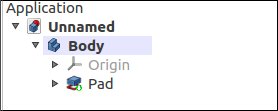
Then select the body and press F2 and rename the body.
Before making the next body, make sure you select the upper name which is the entire project. If you have body selected, the body will be made within that body.
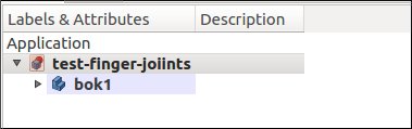
Click new body and new sketch. This time click the XZ-plane and make another square. Have this one start at the same origin as the other one. Give it dimensions and pad it.
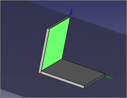
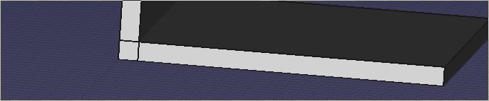
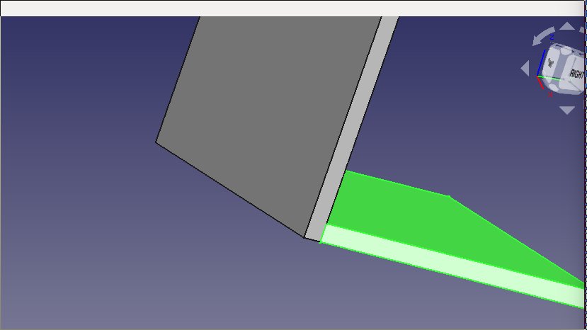
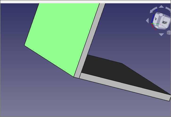
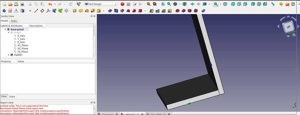
Here you see the pad parameters. For the finger joints you want the blocks to sit on top of each other. You might think you want to select reversed.
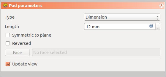
Reversed places the two objects over each other. Like in the picture below. But that is not what you want.
You can’t just apply the fingerjointing to the two bodies I created. FreeCad won’t allow you to add a ‘face’ because they aren’t configured. You first have to prepare them. Select both bodies and go to the Part workbench. Then form the top dropdown menu click Part > create copy > create simple copy. Then hide the original objects by right-clicking them and selecting toggle visibility or press the space bar.
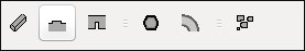
Then select the two copies and select LCInterlacing from the wokbench dropdown menu.
The click the second icon from the left.
A panel with options opens up:
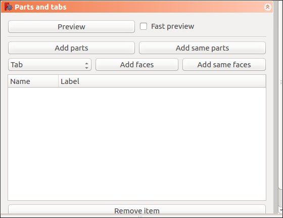
Click add same parts.
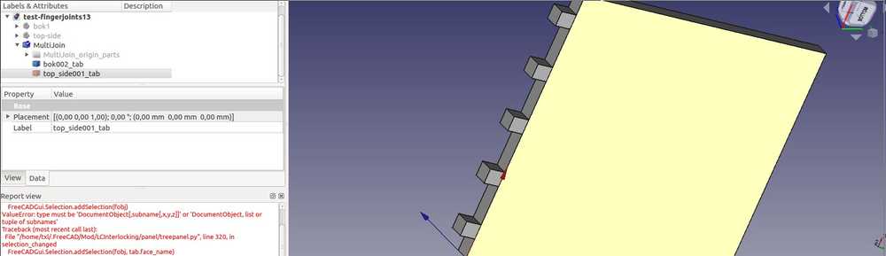
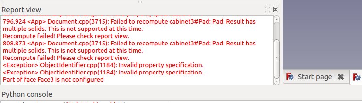
Add faces. And this is when FreeCad throws an error:
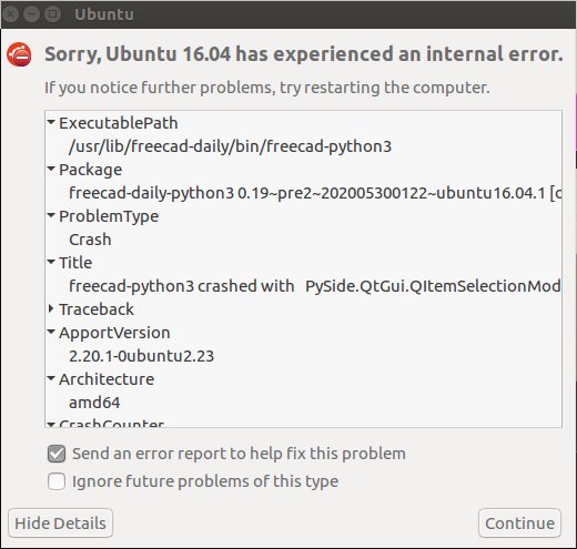
Maybe this will fix it:

So I do sudo apt-get update && sudo apt-get upgrade. And the packages in the error message are indeed in the list of to be updated packages. I close FreeCad and reopen it.
Error remains. No fingerjoints are being made. And I really dislike FreeCad.
Then the error disappears. I don’t no what was wrong or what fixed it.
But I still don’t get finger jointing to work.
I start from the point in the tutorial where the two objects are copied.
In the tutorial they select both objects and click the afore mentioned icon. The panel opens. They click add same parts. After that only one object remains selected.
They then select the part that is no longer selected. And in the tutorial it then disappears. I assume they delete it and that is what I do as well.
Then select the face that was previously touching the other object.
And click add faces.
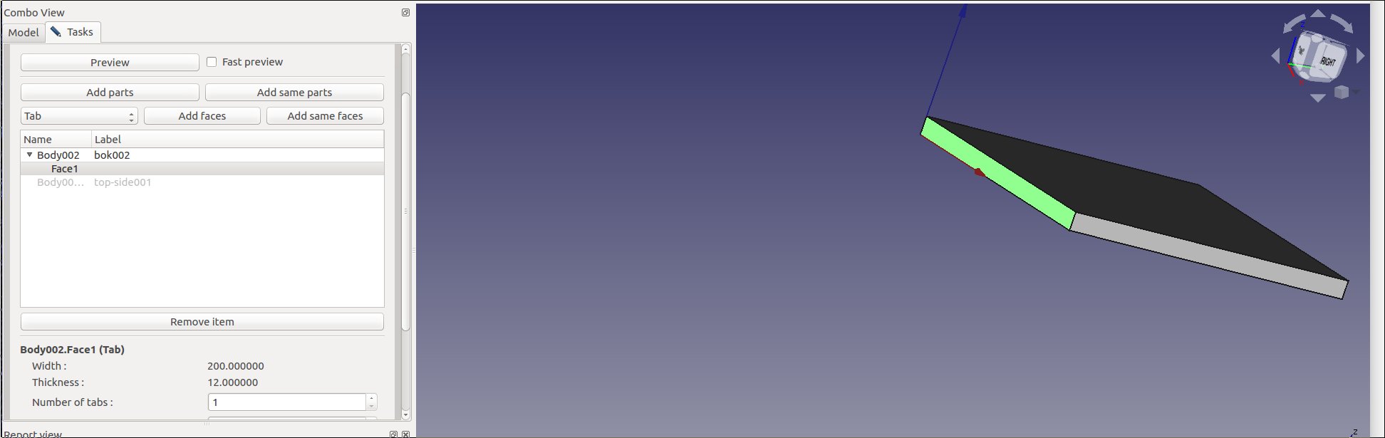
The panel with different options shows up.
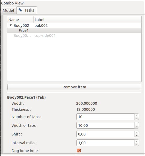
This is the panel you see when selecting Face. You can change the settings.
This is the panel you see when selecting the object.
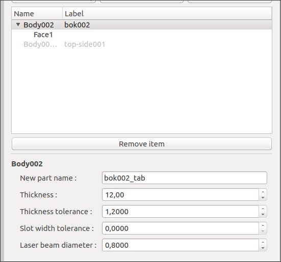
You click okay at the top.
In the project list new items appear. The MultiJoin appears in the tutorial as well. The multiJoin_origin_parts does not appear in the tutorial.
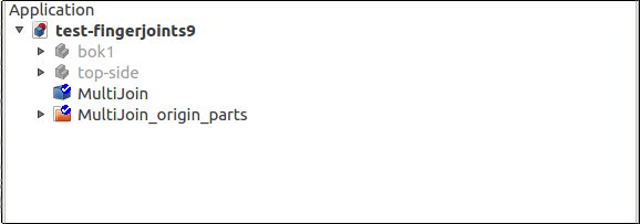
When I click MultiJoin I get a pane with information.
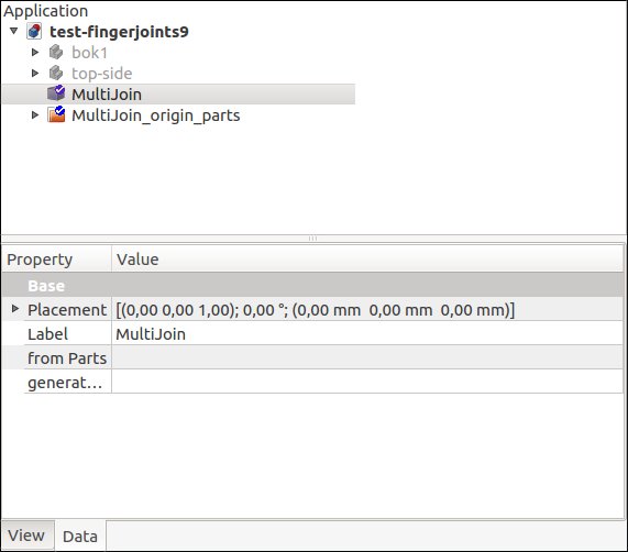
This is what it is supposed to show: from the tutorial.
When I click the extra folder that is not supposed to be there, I get this: A single pane without joints.
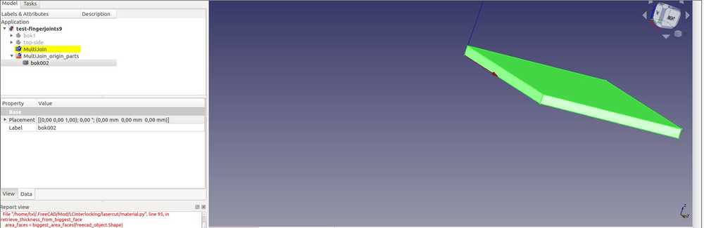
Then instead of delete I right click on the object and click toggle visibility. That makes sense of course. Deleting an object would not be logical step in this process.
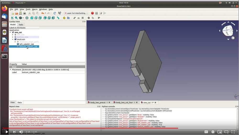
And then I get something that looks similar to the tutorial.
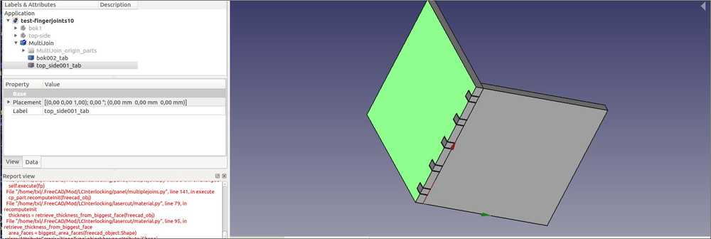
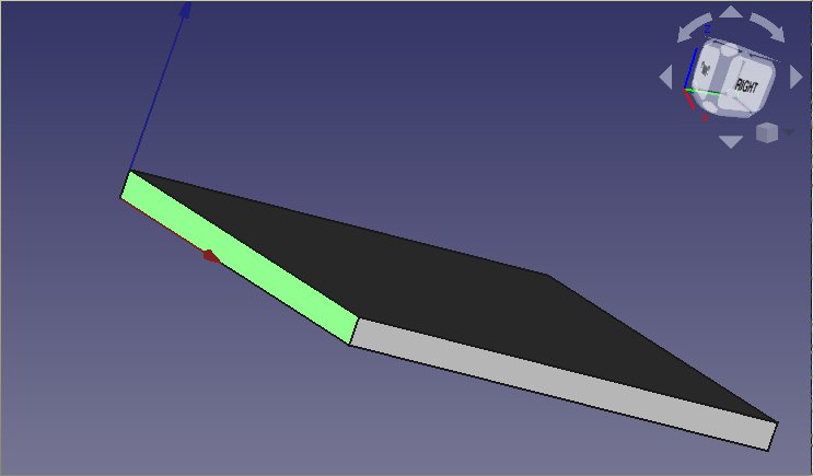
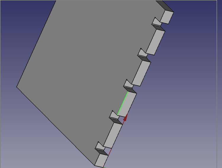
I say similar because one object had fingerjoints. The other has not.
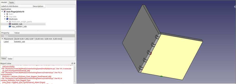
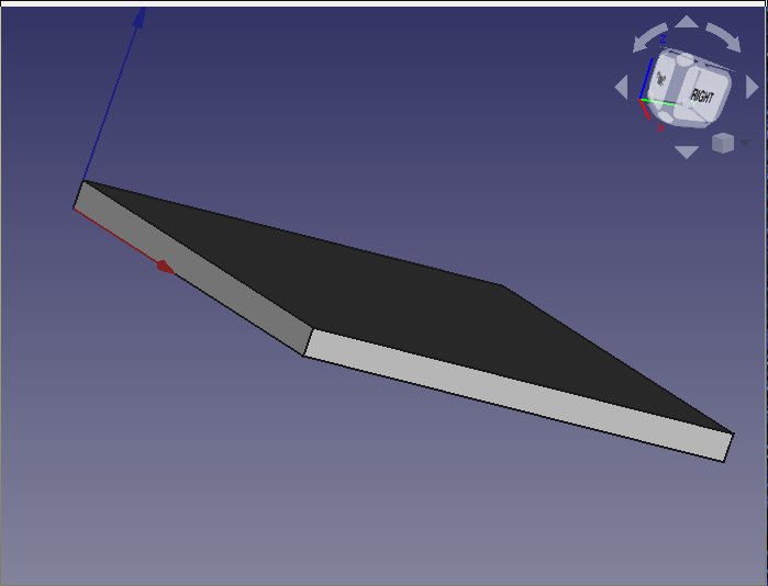
When I make one object invisible it looks like the fingerjoints were made succesfully. But they are not because they pins and the plat surface do not make one object.
Compare to the succesfully made part:
Other FreeCad nice to knows:
I want to have snap-to-grid enabled, so objects will snapp to grid points when placed. Select Draft workbench. Under View > toolbar make sure Draft Snap is selected. A set of icons becomes available. The blue grid icon is snap-to-grid. I think enabling makes the snapping feature enabled in all workbenches.

Change 3D navigation:
You can change the settings for how your mouse does panning zooming etc. Go to Edit > Preferences > Display > Navigation > 3D Navigation. Here you can read what the different settings do. I choose touchpad.
You can save different stages of the FreeCad project by using save as.
New design - Or why I will never use FreeCad again
I can’t adapt the design I made previously. It is a 2D design and the LCInterlocking addon works with 3D designs.
It would be handy if I could re-use the measurements from my first design but there is no discernable way to export the data from one design to another. So I manually copy all the measurements I made into a new project.
- Make spreadsheet and add the measurements in the spreadsheet workbench. Here is a tutorial that starts with using a spreadsheet.
- In the first cell write what the value is. For instance, length-door. This is for your own reference. Than in the second cell write the value, f.i. 100. Then you must add a measurement unit otherwise nothing will happen, so 100 mm. Then you have to right click the cell with the measurement and switch to
alias tab. Here you must enter a name. This you will later use to call on the value. You can’t use dashes in the naming.
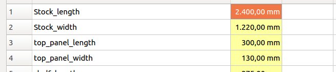
Here you can see part of the spreadsheet. The yellow of the cells indicates they have been named with the method above.
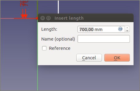
You can call on these values with the formula editor. You enter it by clicking on the little blue circel on the left.
FreeCad won’t show you what’s in your spreadsheet. You have to enter the first three letters of the name you gave it. So you have to remember your names.
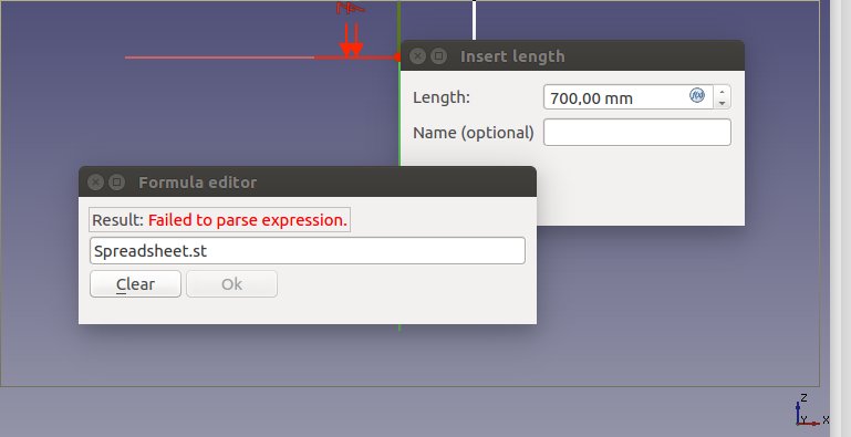
This is what the formula editor looks like: it does not show options. You need to know the names you gave to your values. Only after you’ve entered the first three letters a dropdown menu with options appears.
- Go to Part Design.
- Create body
- create sketch
- Draw rectangular in the sketch
- Select line: SHIFT-D.
- Click on formula editor, the circel thing.
- Start typing spreadsheet and then the name of you value f.i. stock_length. This then calls on the value from the spreadsheet. You can also give the line a name.
- close the sketch.
-
Click padding. Don’t select anything. Just click padding after closing the sketch. I use 12mm, the thickness of my wood.
-
Select the project (not a body because then new body will branch underneath it.)
- New body. For the new sketch select X-Z plane. And repeat the steps
- Don’t press CTRL-Z: FreeCad crashes. And you can start from the begining. Yes really.
I fill out the spreadsheet again. Save. Go to Part Design but now the new body icon is not available. I save, exit the program, reopen and now new body is available.
I now have 2 panels and will see if the finger joint thing will work.
When I try to pad the second sketch the padding is added to the skethc below it. So one object has two paddings and the other none.
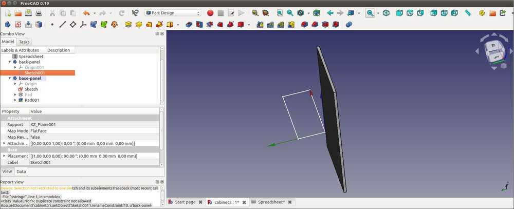
As I try to get the padding done I get an error. I don’t know why suddenly the body’s aren’t active
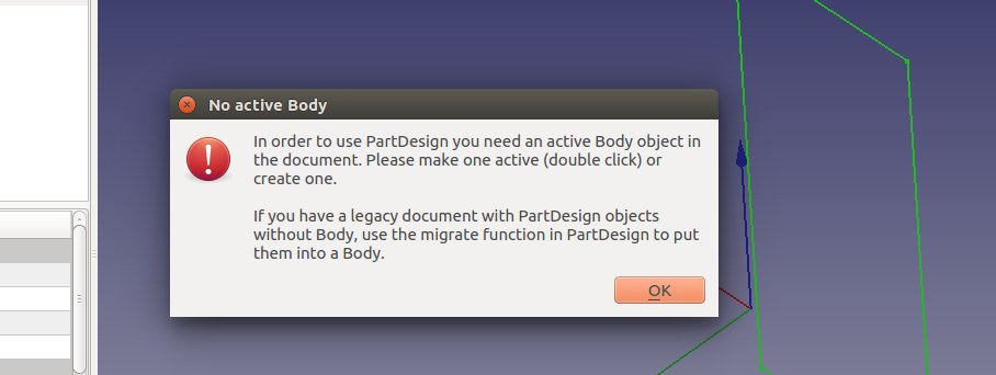
exit program. Who knows, it has randomly changed the behavior of FreeCad before.
Freecad forum says you must first double click a body object. So selecting a sketch from the body branch is not enough. You need to first double click it.
I delete the padding from the lower body. And now first do the padding of the upper body. Now they both get padded. So appearantly you can only pad bodies in one direction.
Adding the top panel and the back panel together I realize that in my old design I made the lower panel 24mm less wide than the backpanel. Idea was that side panels slide over it. But now with finger joints they need to be the same width. Just adjust it in the spreadsheet: parametric design! But when I change the value in the spreadsheet, the length of the object does not adjust. The reason may be that the object is padded. But when I remove padding the problem persists. FreeCad says: ‘invalid property specified’. So I delete the length constraint from the object and go through the process of adding the constraint again. So much for parametric design.
And then finally:
- Now make a back up of your project with
save asin a project nameduncut. Do this after every operation because finger jointing can’t be undone. You can’t change your sketches anymore. - Select both bodies and go to Part workbench.
- Create simple copy
- Hide your original objects by pressing
space. - select both copied bodies and call the LCinterlocking workbench.
- Click the second icon from the left.
- Click add same parts.
- Hide one object to select the face of the other.
And when I do that I get the ‘ facenot configured’ error. This is mentioned in the tutorial and this is what the make simple copy action in Parts workbench is supposed to solve.
The FreeCad forum says something about parts being automatically hidden. And that this may cause you to have multiple parts occupying the same 3D space and therefore you are unable to select a face.
Maybe the simplecopy in Parts is the object occupying the same space. Even though this was done by the person in the tutorial to prevent this error from showing up. But when I try again without copying I not only get the same ‘Face is not configured’ error but another program crash as well. The Ubuntu crash reporter is again indicating packages may be missing. Even though I added packages the previous time this crash occured.
I’ve now spent an entire day on FreeCad for quite a simple design without any result. I will make this assignment in another program. And I shall never use FreeCad again.
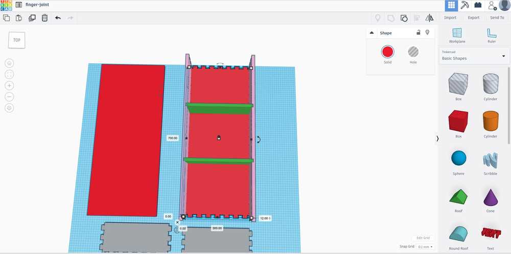
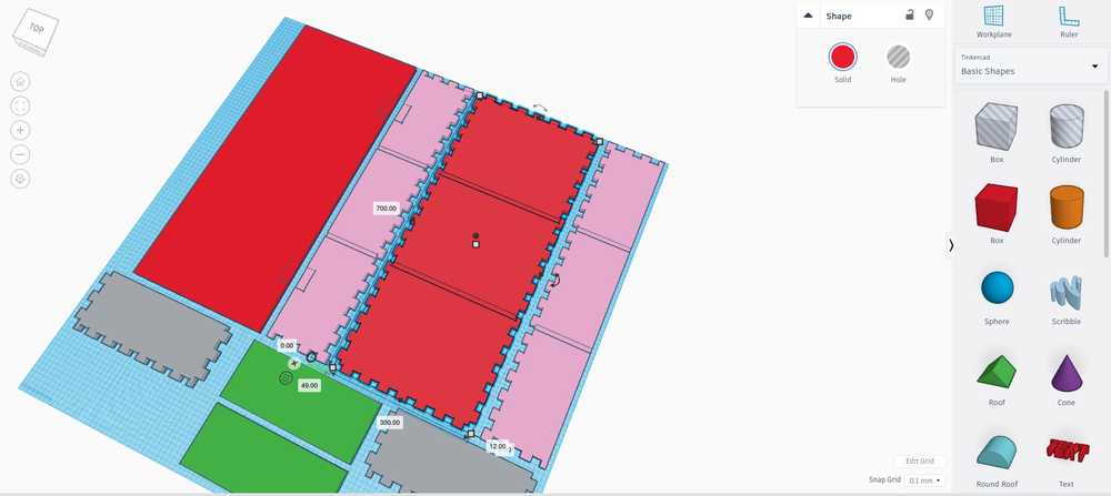
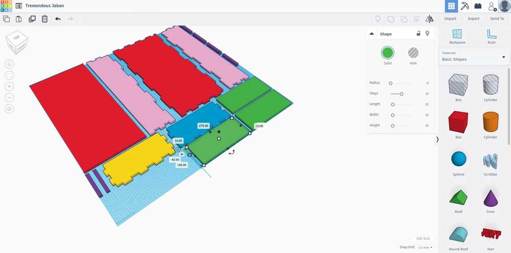
Remaking the design: TinkerCad
Making chafers
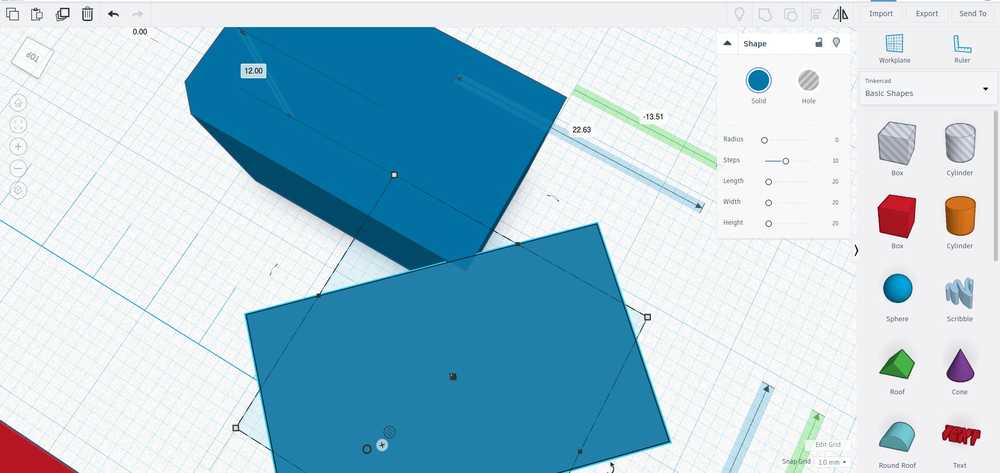
Making joints
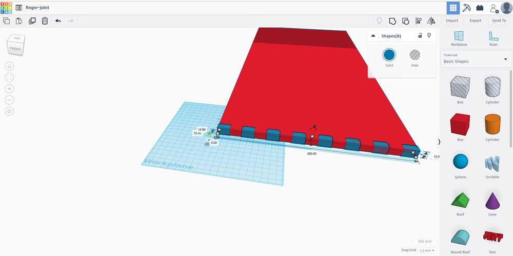
Tinkercad warns: object exceeds size limit. To fix under edit grid make grid larger.
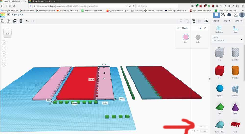
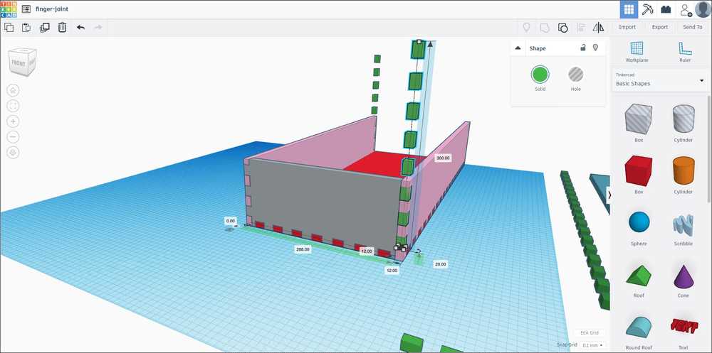
Indents for the shelves
When exporting from TinkerCad make sure you select all objects, otherwise you get only the last selected in your STL file.
Inkscape (via V-Carve)
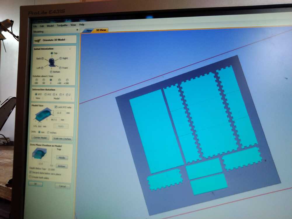
TinkerCad exports as OBJ STL or SVG. I used STL during casting and molding so I did that again. I import the STL file in V-Carve.
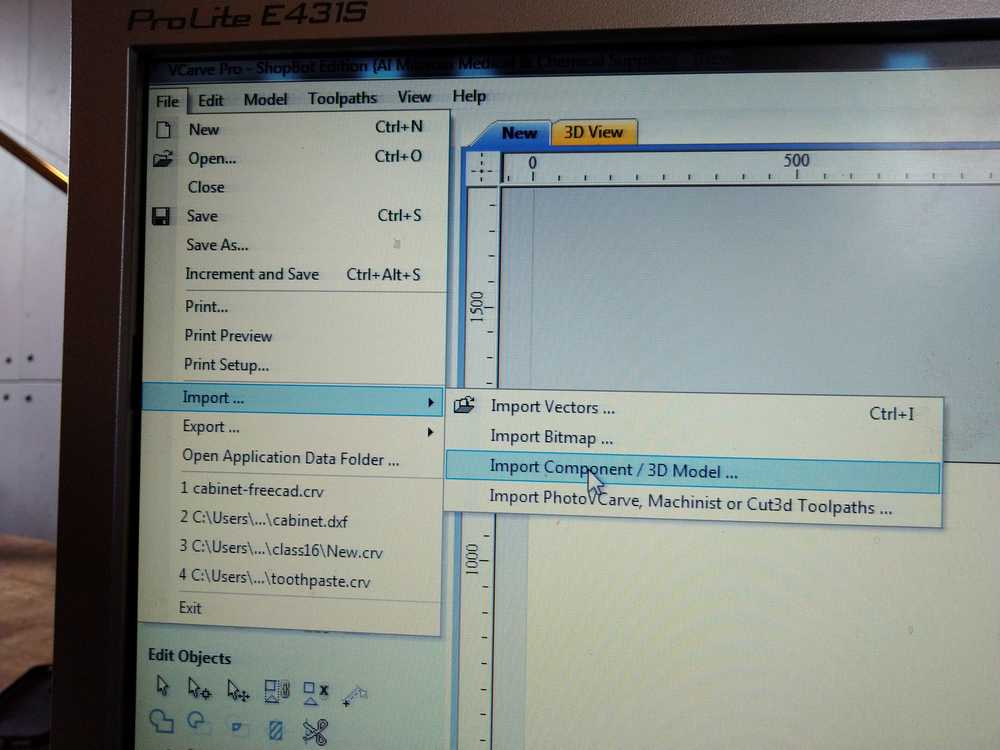
But this makes it into one big object, which is good for 3D milling.
Rutger explained that for 2D milling you only want vectors. So export from TinkerCad as SVG. And turn it into a DXF in Inkscape.
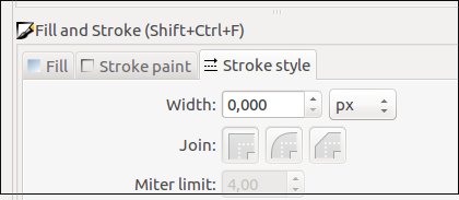
But when I export SVG from tinkercad no lines are showing… Oh wait! I had this before. The lines are so thin you can’t see that. You can adjust the thickness of the line in Inkscape with fill and stroke. object > fill and stroke. Then in the left panel first select the stroke paint tab and select flat color.
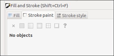
Then under stroke style adjust the width.
But now my pockets for the hinges and shelves are gone that I made in TinkerCad are gone. Internet explains that TinkerCad makes the SVG where object and workplane intersect. So I’ll try lowering it to point where pockets start.
Not a good idea. It works but the engraved lines are now cuts. (Later, when I understand better what is possible in V-Carve I realize I could have adjusted the pockets in Inkscape and select them for the pocket toolpath in V-Carve.)
Since I am not sure if my pockets are coming out I have to add supports for the shelves. And adjust the size of the shelves. As they now will not be fitted into the cabinet but resting on supports
This is what it looks like.
Exporting to DXF and importing in V-Carve.
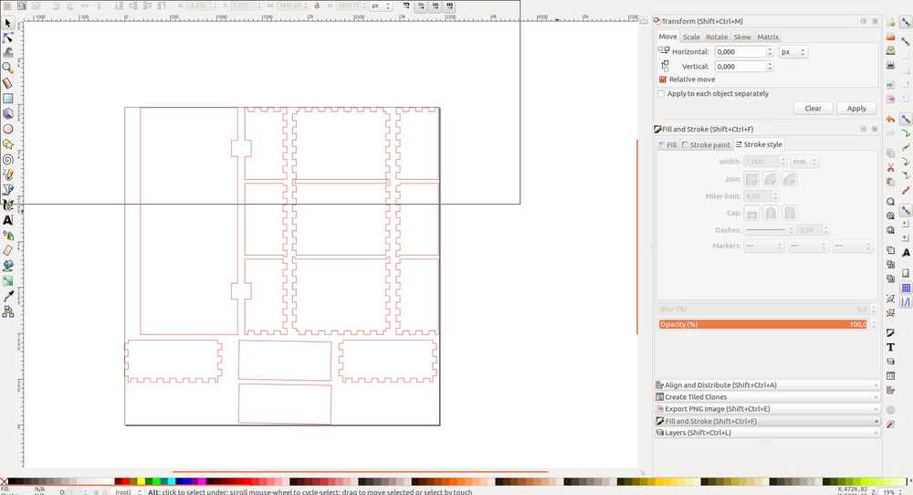
Inkscape has exported a mini-cabinet. Back to Inkscape, set document settings to the size of my stock material. On the same page I set default units to mm. Then I use the ruler tool (icon on the left)  to measure individual objects and they are the right size . You can also use the arrows to move.
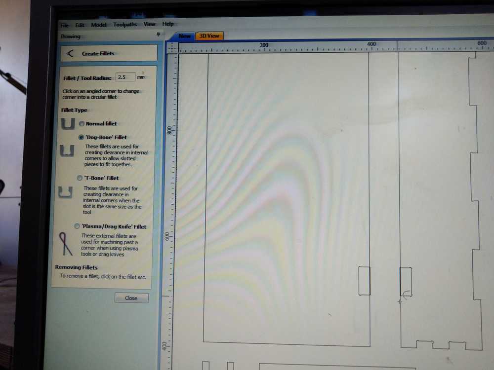
V-Carve
Open a new file.
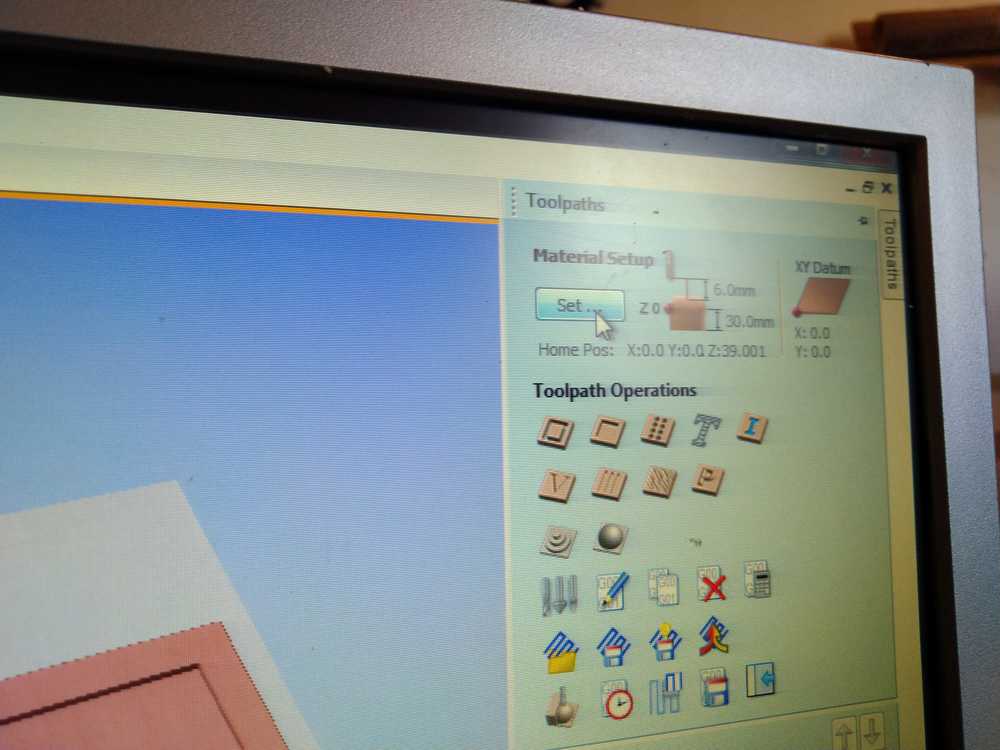
Material setup. Set dimensions of your stock. Choose XYZ axis settings. The settings in the picture are the default and recommended.
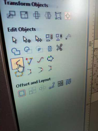
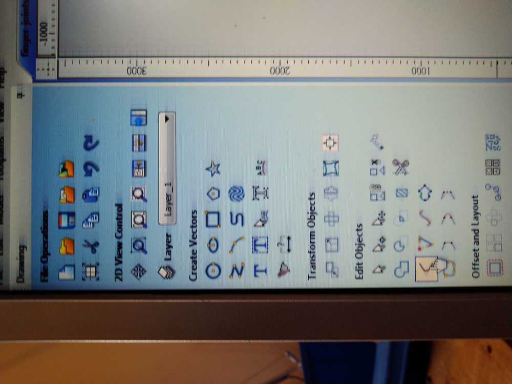
This is the drawing panel. Here you can alter your design. You can add dog bones for instance (more on that later). Note that there are three types of selection tools. To drag and drop select the right pointer-arrow. Then you have to hover over your object. The pointer changes shape. Each shape is a different function: rotation, drag etc.
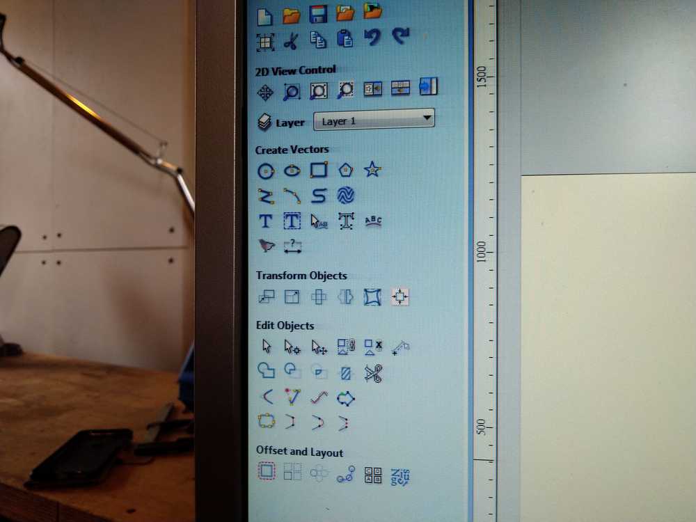
I use the drawing panel to make some adjustments to my design. I add lines for the hinges. And I organize the different objects more neatly so it makes better use of the material. It is better to do this operation in your design program.
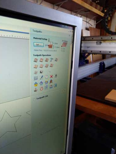
On the right side of the monitor there is the toolpaths tab. When you click it a new menu opens. The wooden like icons indicate different types of toolpaths. The icons underneath provide other options like toolpath preview or save toolpath.
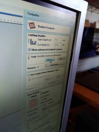
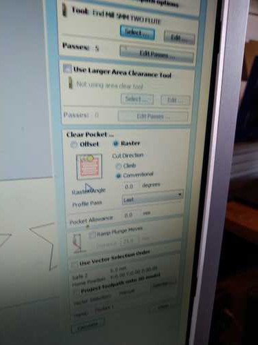
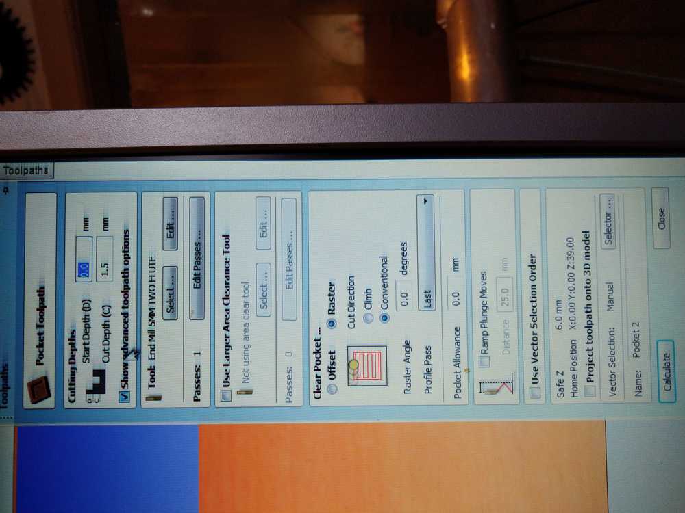
Click the pocket toolpath and it opens in a new menu. Here you can indicate how deep you want your pockets to be. I put mine on 1.5mm as that is the thickness of my hinges.
You can select the drill you want.
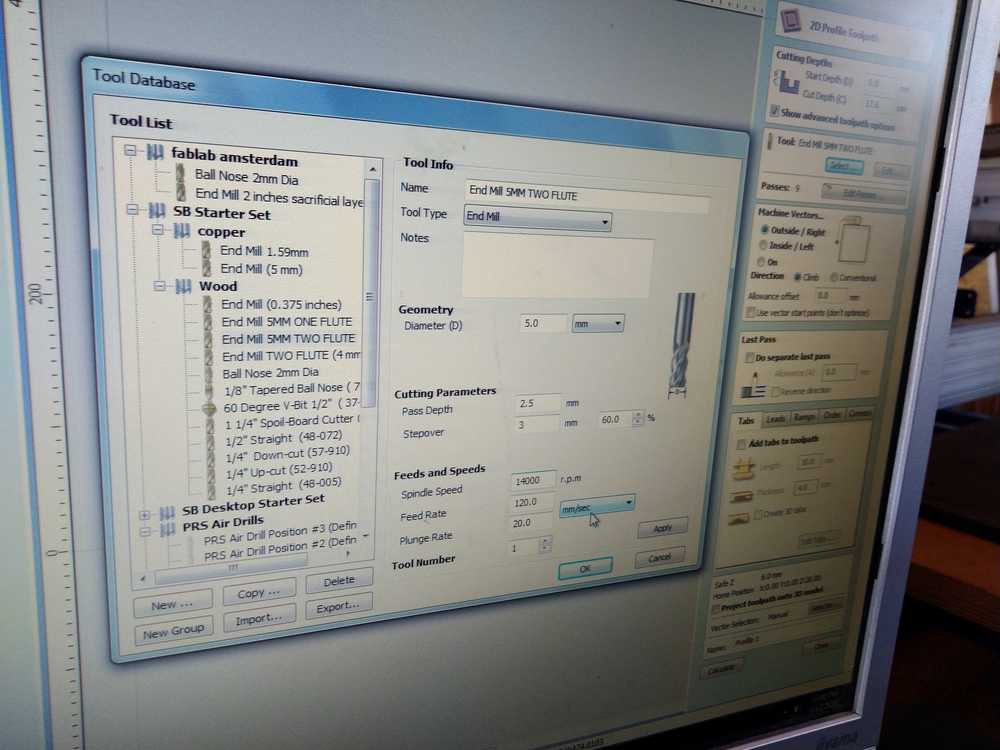
The settings I use:
5mm end mill two flute
Pass depth: 2.5 mm (default is 50% of drill dialmeter).
Stepover 3.0 mm (60%)
spindle speed 18.000 rpm
feed rate 80
plunge rate 40. Plunge rate is how fast the Z-axis will plunge up and down. You could set this higher but for 2D milling it does not matter that much. But when you are 3D milling it really matters. If it slow (like 20) the milling job will take much longer.
Raster is the default setting for pockets.
Conventional for roughing, climb for finishing.
The other settings I don’t use.
Finish by clicking calculate toolpath.
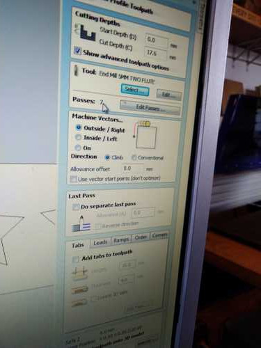
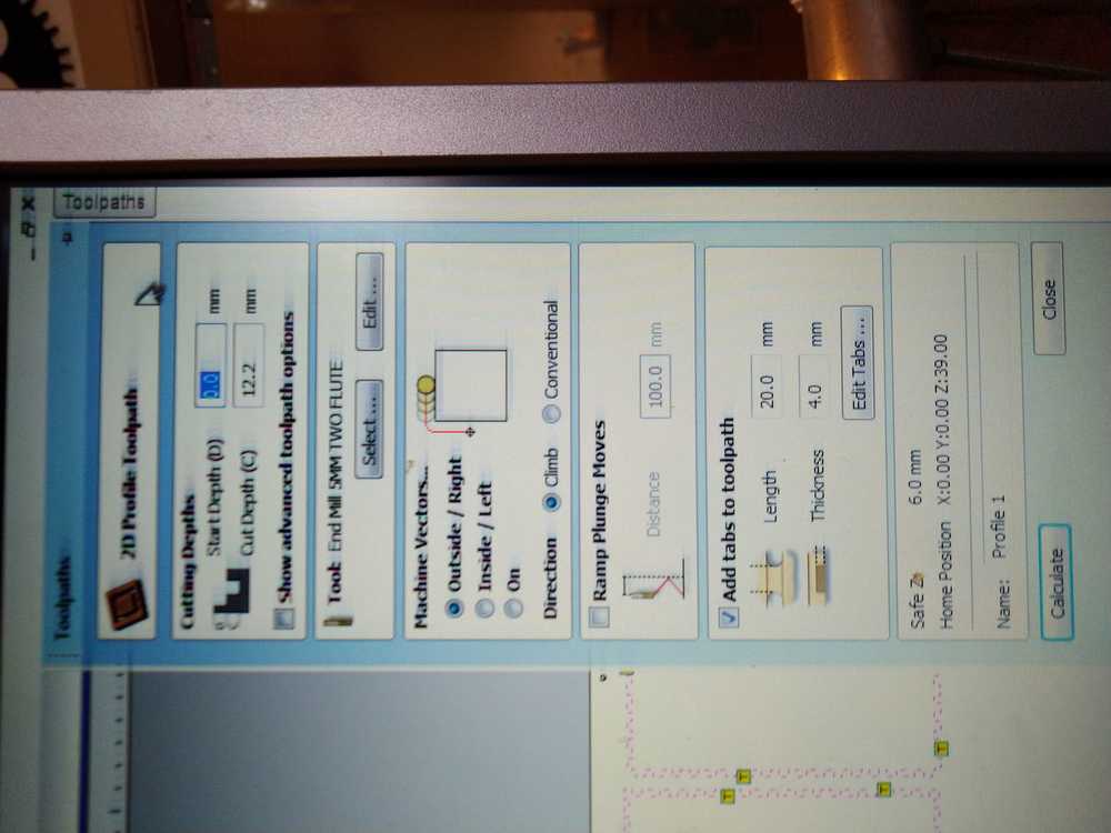
Next I select the cutting toolpath. This is for cutting through the entire material.
Cut depth: Rutger advises to add 0.2 mm to the thickness of your wood. That way you are sure it will cut all the way.
Again the option to choose your drill.
My settings:
Pass depth: 2.5 mm
Stepover 3.0 mm (60%)
spindle speed 18.000 rpm
feed rate 80
plunge rate 40.
Machine vectors: I choose to mill outside the line. I asked Rutger and that is necessary for press fit. Inside the line you will loose material that is part of your design. Finish by clicking calculate toolpath.
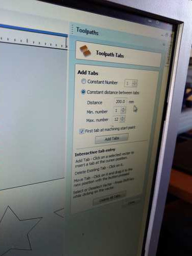
Tabs: click to edit the tabs. V-Carve places them but you want to make adjustments. You daon’t want tabs in corners because you will never get them out. For my 700mm pane, Rutger advise 3 tabs. When in the edit tab window you can click on a tab and it will disappear. Click on a line and it will add a tab.
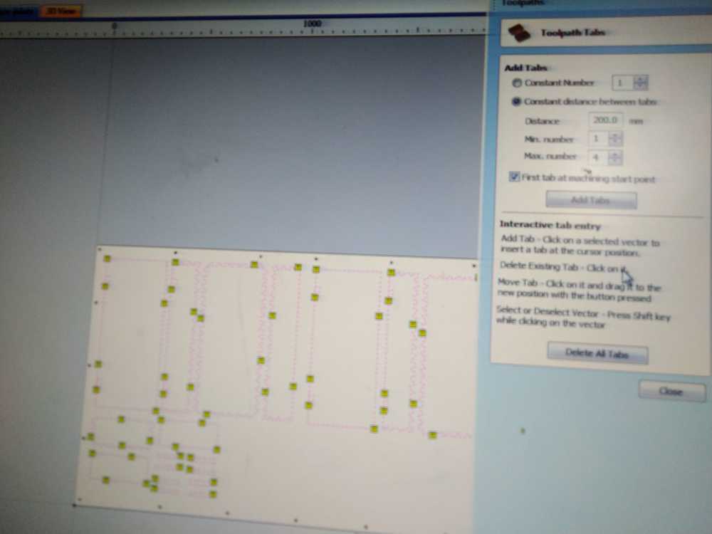
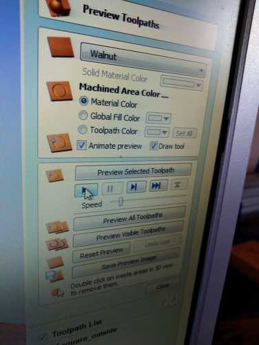
After you’ve added tabs, dog bones etc. you calculate the toolpaths. You can access this feature through the toolpath menu. You can choose to show one toolpath or all. Reset preview will remove all toolpaths from the model so you can start a new preview.
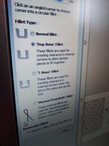
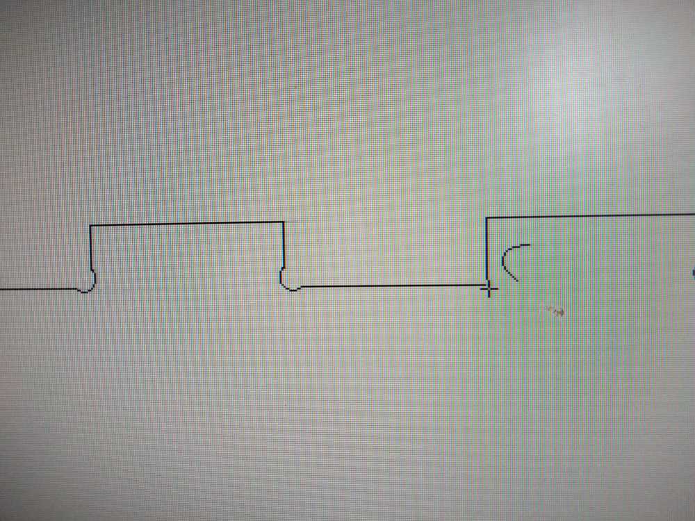
Dogbones
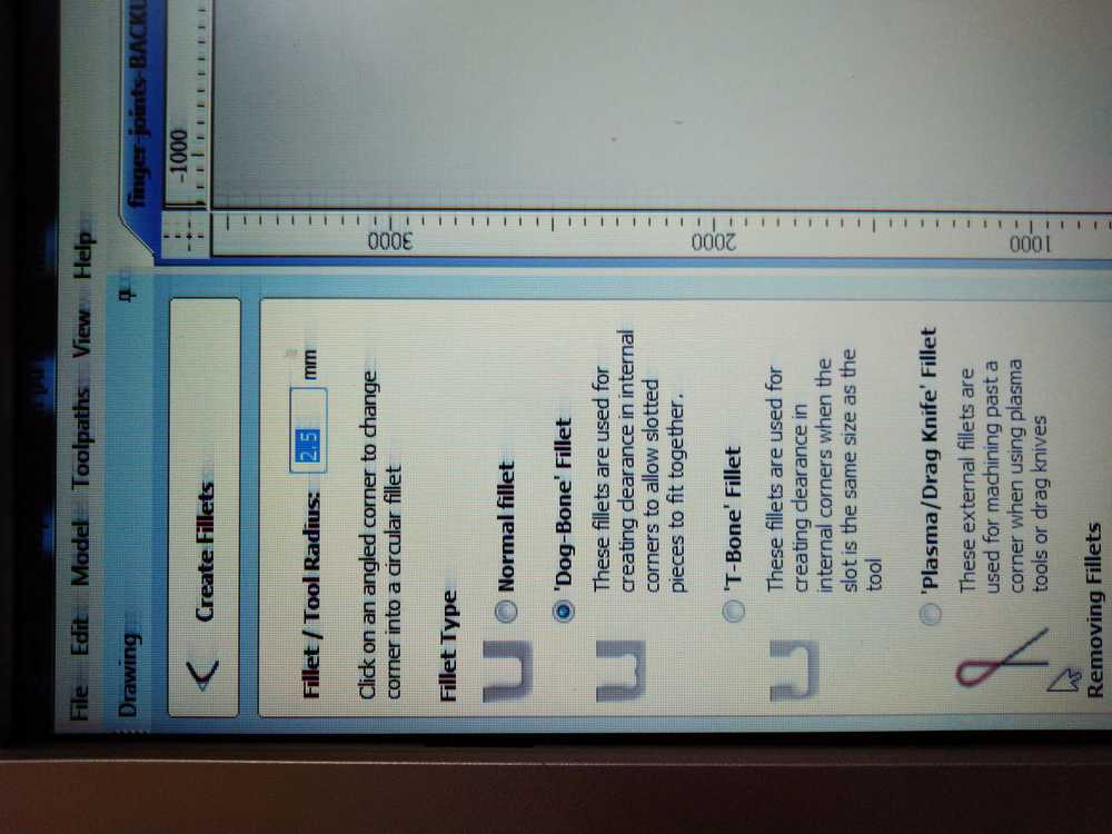
The mill, being round can’t mill sharp corners in the inner pockets. Therefore you add dogbones. These are little arounds that allow the mill to get in all the way. Dog bones are 50% of the diameter of the end mill. So 2.5 mm dog bone for the 5mm drill. If you do not add them your model will not be press fit.
Select this icon in the drawing panel:
Choose dog bone:
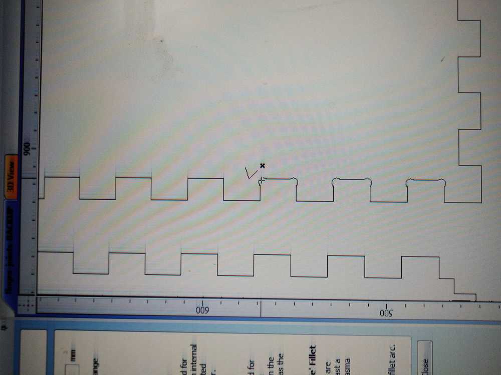
Add a dogbone by simply clicking on a corner.
Another design
Rutger said I had too many finger joints. They are small (20mm) which can be less sturdy. Adding the dog bones I realized each pocket will loose an additional 5mm (2x2.5mm) which would make the whole thing rather flimsy. I looked at Quinten’s page. He added 4 joints per side, rather than having all the joints the same size he adds a number of joints per side and thus adjusting the size of the joints. I’ll do that too. (For next time, I should’ve used an odd number for the amount of finger joints. That way you have fingers (or joints) on both ends.) But the top and bottom are to small to divide by 8, so I’ll devide it by 5.
Dimensions:
door: 700x300x12 mm.
shelf: 276x128x12 mm. But I remove 1mm from the side and 2mm from the top to make sure everything fits. So: 275x126x12 mm.
top and bottom: 300x140x12 mm.
Fingerjoints:
Door = 700x300.
700/8 = 87.5 mm joints.
300/8 = 37.5 mm.
Top = 300 x 140.
300/8 = 37.5 mm.
140/5 = 28 mm.
I measured the material with a ruler. At that moment I could not find the digital measuring device from the lab that is super precise. (It was missing for two days and we all missed it a lot. Harm missed it so much he asked one for himself for as a birthday present.) The crude reading from the ruler was that the stock material was indeed 12mm thick. Later, after I had already milled the wood, the digital measuring device magically re-appeared. The stock material measures between 11.88mm and 11.93mm.
When the material was cut the joints and fingers did not immediately fit. I had to sand off about 0.5mm from both the joint and the finger. This is a rough estimate, I just sanded until it fit. Rutger had said up front that if you cut with the setting: cut outside the line in the cutting toolpath, you will need to do some sanding to make the design press fit. He said he prefered it that way because you have more control over how it will fit. It seemed like solid advise and I followed it.
In the group assignment we also saw this. We made a square of 150mm x 150mm. With the cutting-outside-the-line setting we measured an actual square of 151.15 on one side and 150.78 on the other. I did not measure my design after it was cut. But it did take quite a bit of sanding for the joints to fit. So, having to have sanded off about a millimeter on avarage does sound about right.
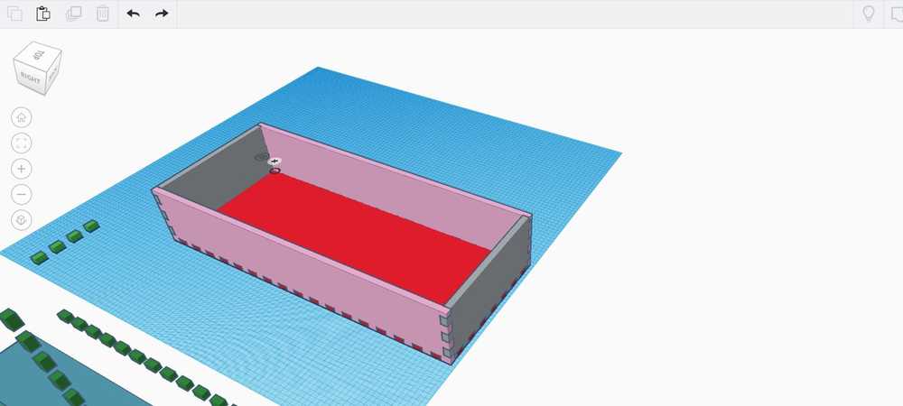
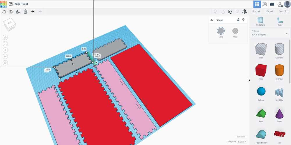
Final design TinkerCad.
Final design Inkscape.
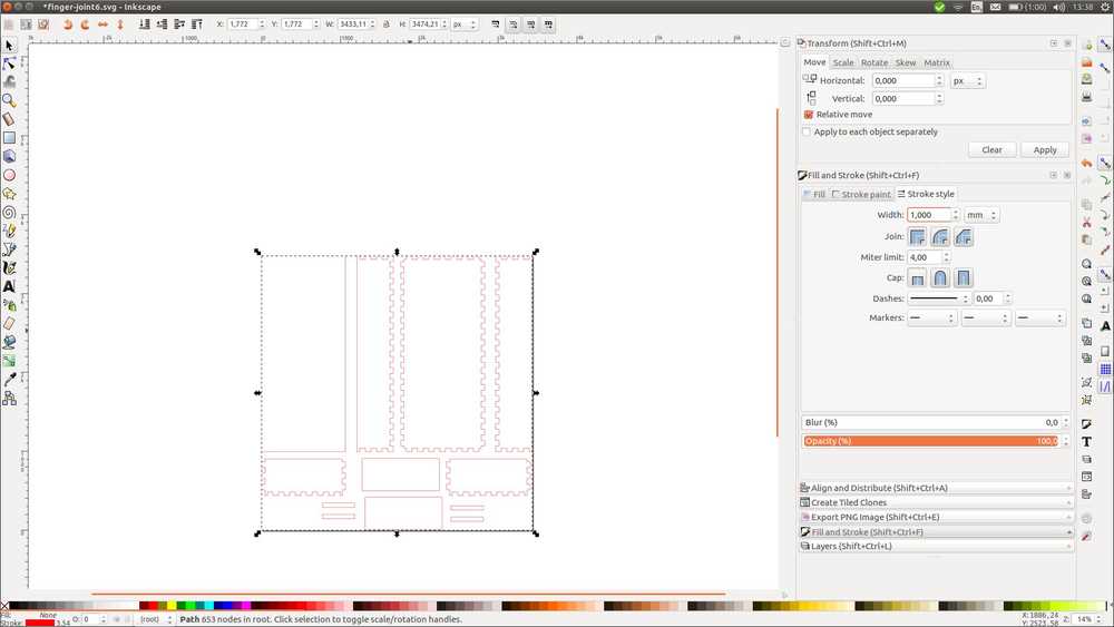
I measure the objects with the ruler, just to double check. Measurements a bit off. So instead of using fill and stroke to make the lines visible, I use view > display mode > outline. This keeps the line at its original thinness but also lets you see them. Now when I measure, all measurements are okey. I export to DXF.
V-Carve
I import my design file and measure the distance between the object.
Starting with material setup.
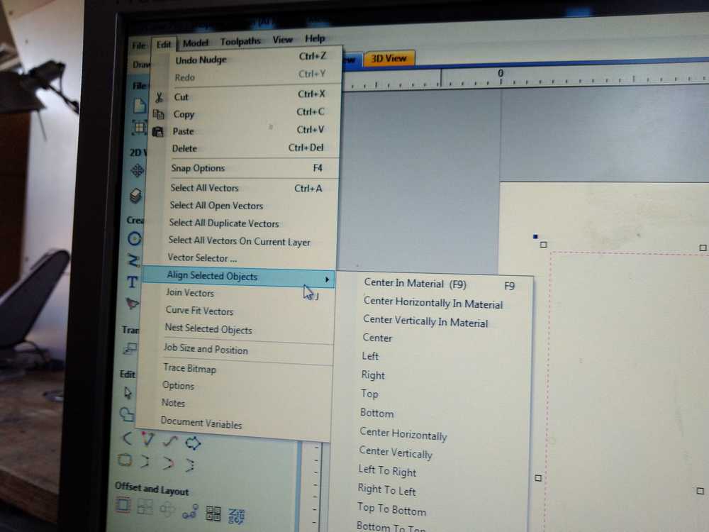
Importing my design file.
I’ve given 2cm so the 0.5mm drill bit has room to drill between the objects. You can align objects under edit > align object.
Settings for the toolpaths:
pocket toolpath:
5mm end mill two flute
Pass depth: 2.5 mm (default is 50% of drill dialmeter).
Stepover 3.0 mm (60%)
spindle speed 18.000 rpm
feed rate 80
plunge rate 40. Plunge rate is how fast the Z-axis will plunge up and down. You could set this higher but for 2D milling it does not matter that much. But when you are 3D milling it really matters. If it slow (like 20) the milling job will take much longer.
Raster is the default setting for pockets.
Conventional for roughing, climb for finishing.
Cutting toolpath:
Cut depth: add 0.2 mm to the thickness of your wood. That way you are sure it will cut all the way.
Again the option to choose your drill.
My settings:
Pass depth: 2.5 mm
Stepover 3.0 mm (60%)
spindle speed 18.000 rpm
feed rate 80
plunge rate 40.
Machine vectors: I choose to mill outside the line.
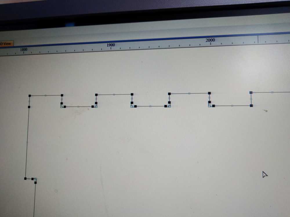
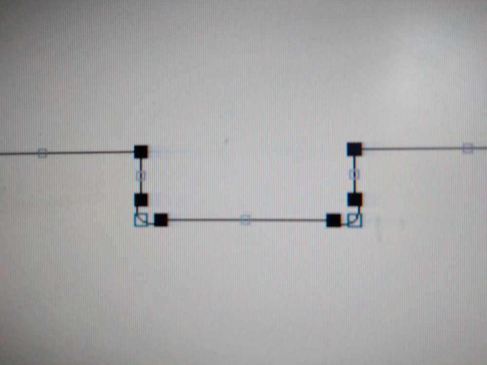
Adding dog bones of 2.5 mm. V-Carve can also detect dogbones automatically. Some corners do not want to be dogboned. V-Carve forumsays it has to do with Nodes. You can select Node view by pressing N and then select an object (otherwise the nodes won’t show.) Forum says: “It only works of there is a long enough section for it to fit. Turn on nodes and make sure the corner where it doesn’t work doesn’t have a short vector right at the corner.
It also doesn’t work if one side of a corner is a curve, and I’ve seen files where what looked like a straight line were actually all curves. Both situtations should be revealed if you turn on “N”odes.” But I don’t see a difference between the corner that works (left) and the one that does not (right). I don’t get the dog bones to work in a couple of places. But I will move on now. Will have to do that manually.
Nodes.
I add the screw points.
I add the tabs.
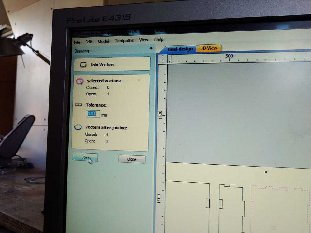
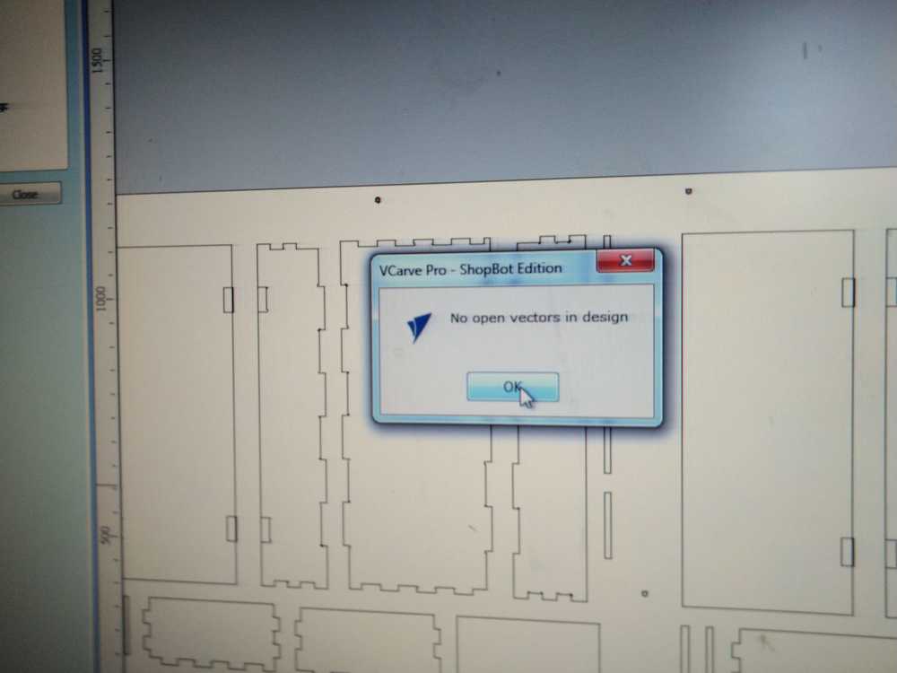
Then when I press calculate for the cut toolpath I get a warning I have open vectors. V-Carve manual says you can close them with the vectors tool.
To see which vectors are open: EDIT->Select all open vectors. This does work but does not show the node that is open. To highlight the open node (after EDIT ->Select all open vectors) just select the menu item “Offset Selected vectors” and the node(s) will be highlighted.
I had hoped this would help also against the dog bones problem but that is not the case.
As described above, I added 0.2mm to the cut depth. So I press okay.
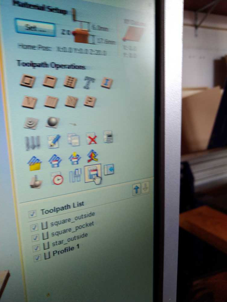
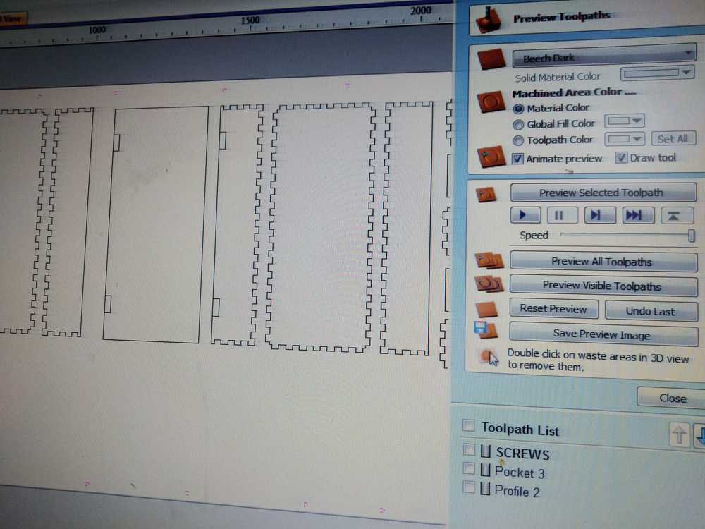
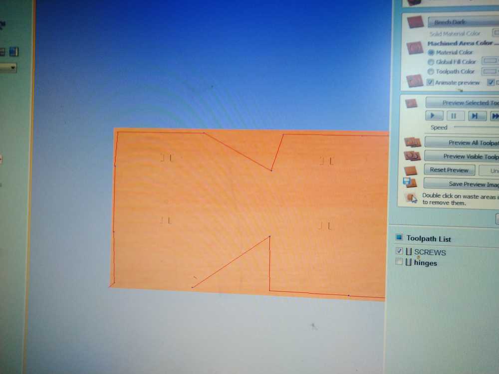
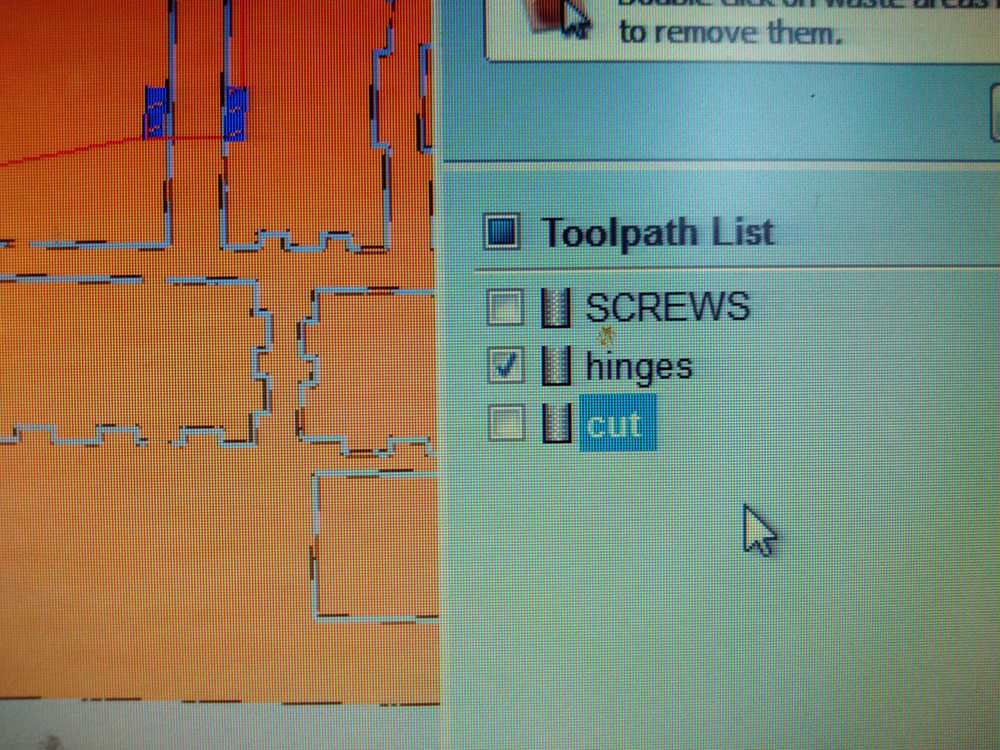
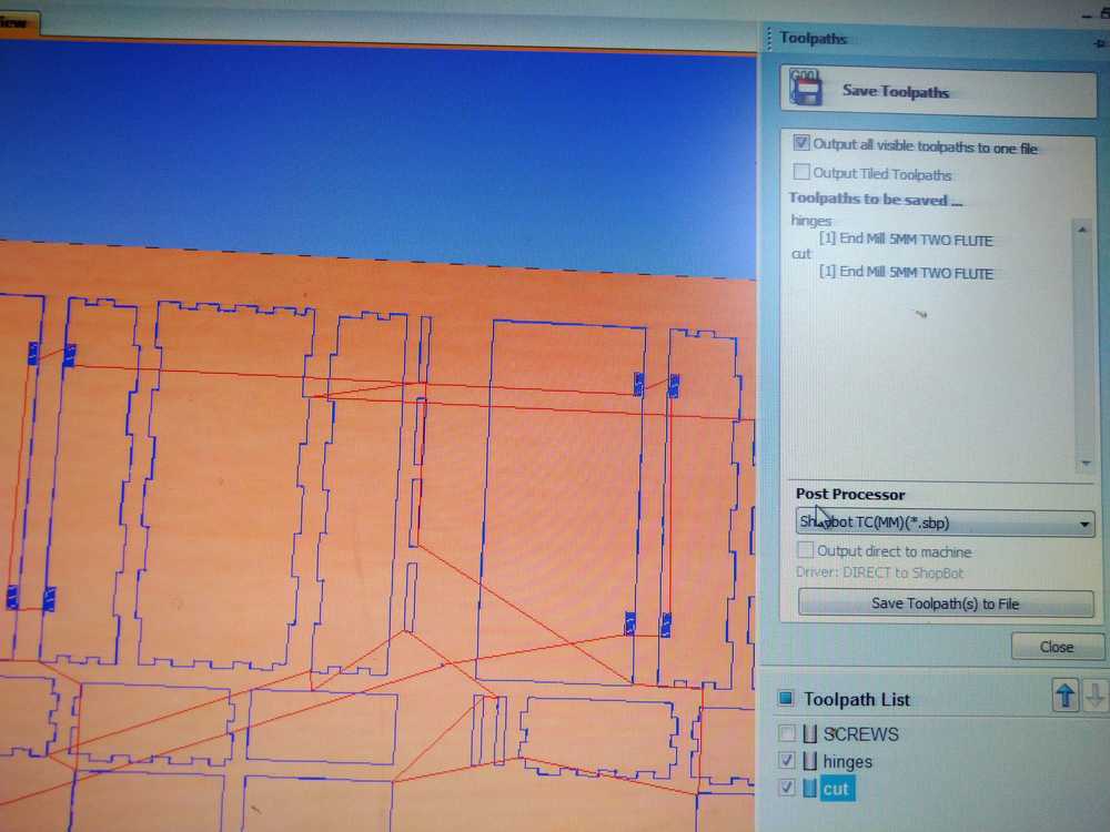
I preview toolpaths. For the Preview selected toolpath it is not ticking the box that selects your toolpath but clicking the name and it becomes bold. The save the screw toolpath seperately and the pocket and cut toolpaths as one file. Don’t forget to save your V-Carve project.
Milling
For my own reference I copy my remarks from weeks ago here:
Things to remember when I start milling this design
- Move the pieces 2 cm apart.
- make hinge pocket 1.8 mm. (50mmx20mm)
- Make marks on the stock to place the screws. Run that first.
- Add the screws.
- Remove screw markings from the design.
- First mill the pockets on the door for the hinges.
- Drill the rest with setting drill on line.
- When done, check if the elements fit together.
- Make adjustments to the design if necessary.
- Refasten the stock on the bed & repeat for the second cabinet.
- tabs
- dog bones
- Take a picture of X&Y settings (no longer relevant now that the Shopbot does not now its own origin.)
Material setup.
Checked if nothing leans against the machine.
Checked my clothing for loose ends.
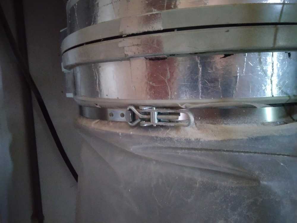
Changed the bag for the dustcollector. You open this fastener and wriggle the bag in the right place. Then tighten with fastener.
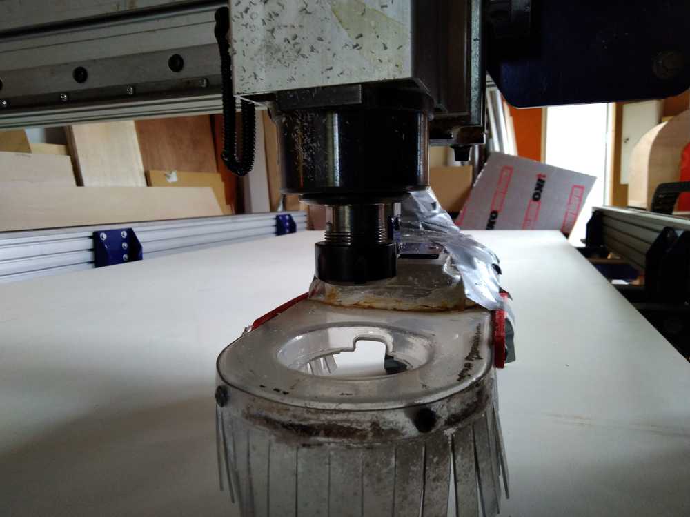
Changing the drill bit.
Lowering the jacket.
Choose right size collet and drill bit
Check if the drill length is long enough for my job.
Fasten the drill bit.
Turn on machine.
Open Shopbot software.
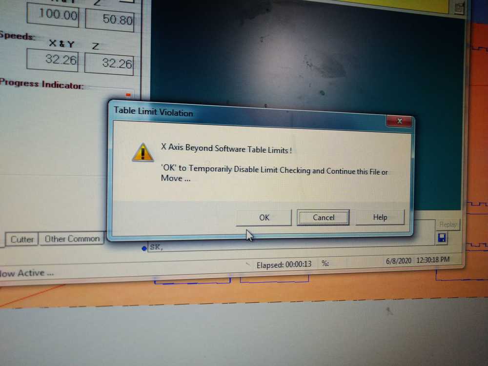
Software has found the machine.
Shopbot still has an issue with finding its own origin. We click okay to get around it.
Zeroing the Z-axis - final version
(This text is copied from week 15 when I figured this out. Images are new.) Zero X-Y axis.
Move bridge to point you want to make origin.
- put the plate steady under the drill. Don’t touch it while it is zeroing.
- Touch the drill with the plate and check if the green button lights up.
- Click the ICON Z. not the dropdown menu. Not the 0.0. But the Z icon.
- The Z-axis will now zero itself.
- Manually make the Z go up.

Same as for the Z: here is the final version for zeroing X/Y.
Bring the drill to the desired pont. Use the dropdown menu (not the icon!) Zero > zero X/Y.
Load V-Carve project. I start with the screws file.
Turn on the dust collector.
turn on the machine by turning the key. You can turn of the drill rotation by turning key off.
Turn the spindle speed to the desired speed with the up and down buttons.

Running the screw job first.
You can follow the progres of the job in the progress panel.
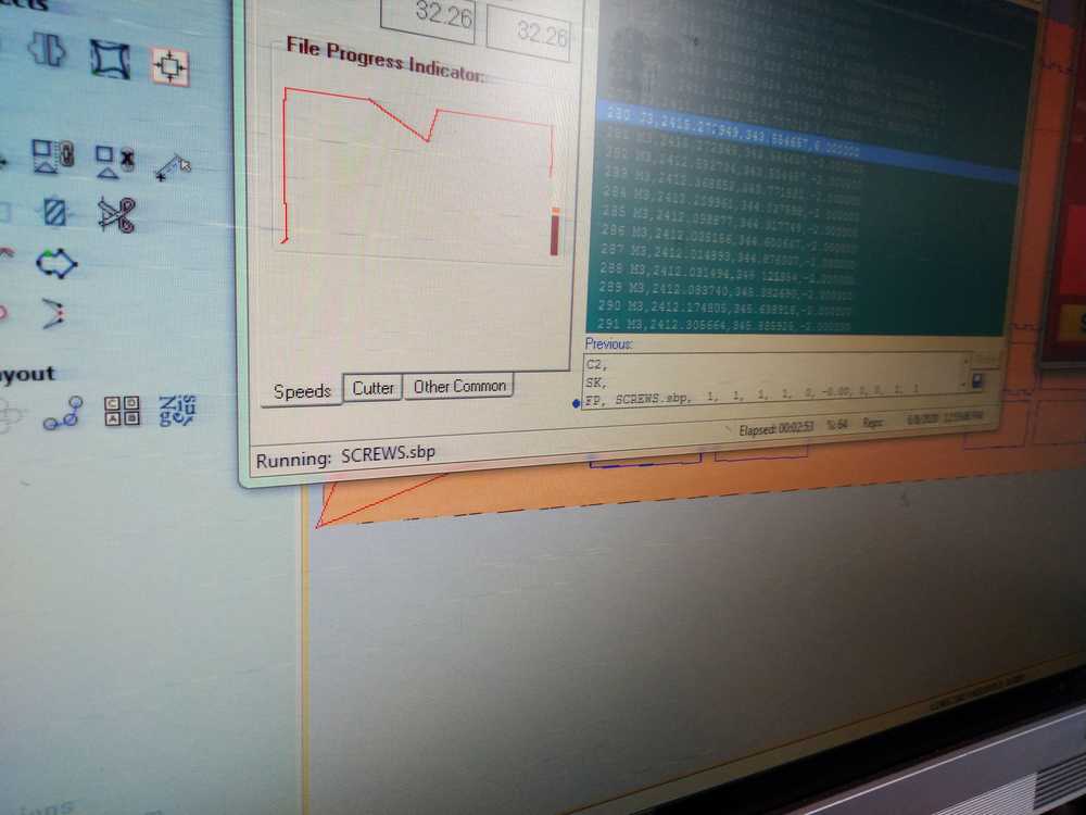
Drill in the screws. Make sure screws are not longer than sacraficial layer.
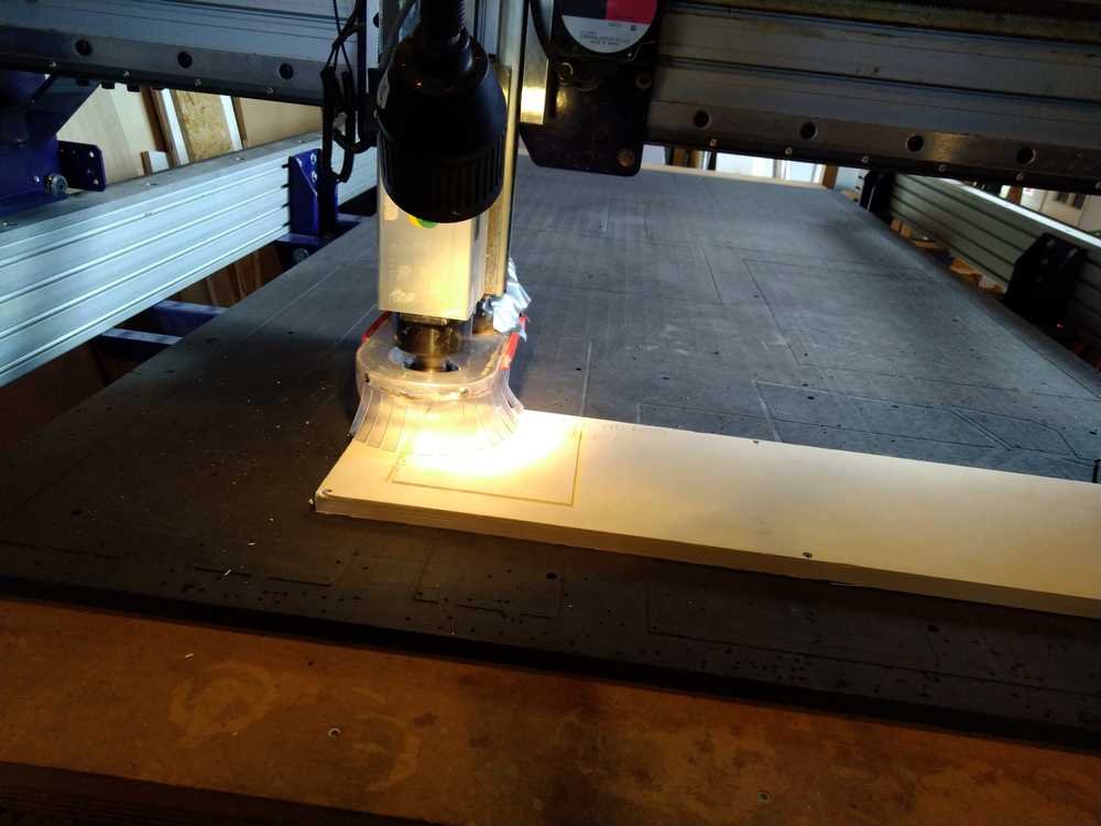
And then finally more than 10 weeks after it was planned
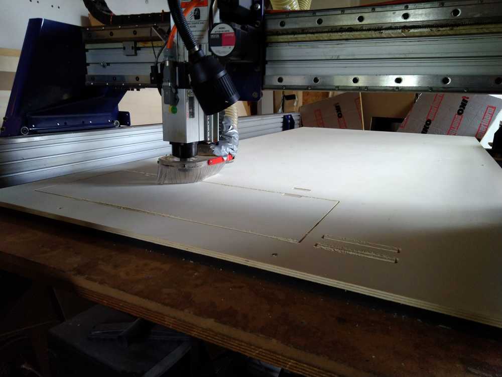
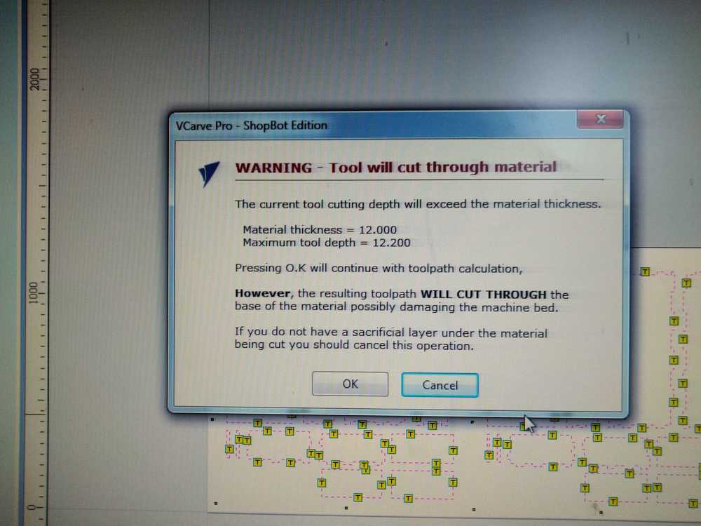
The cut was not deep enough.
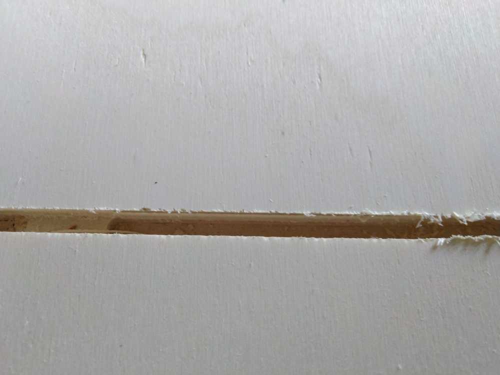
It is about a millimeter from the sacraficial layer. I can remove it with some force with the Stanley knife.
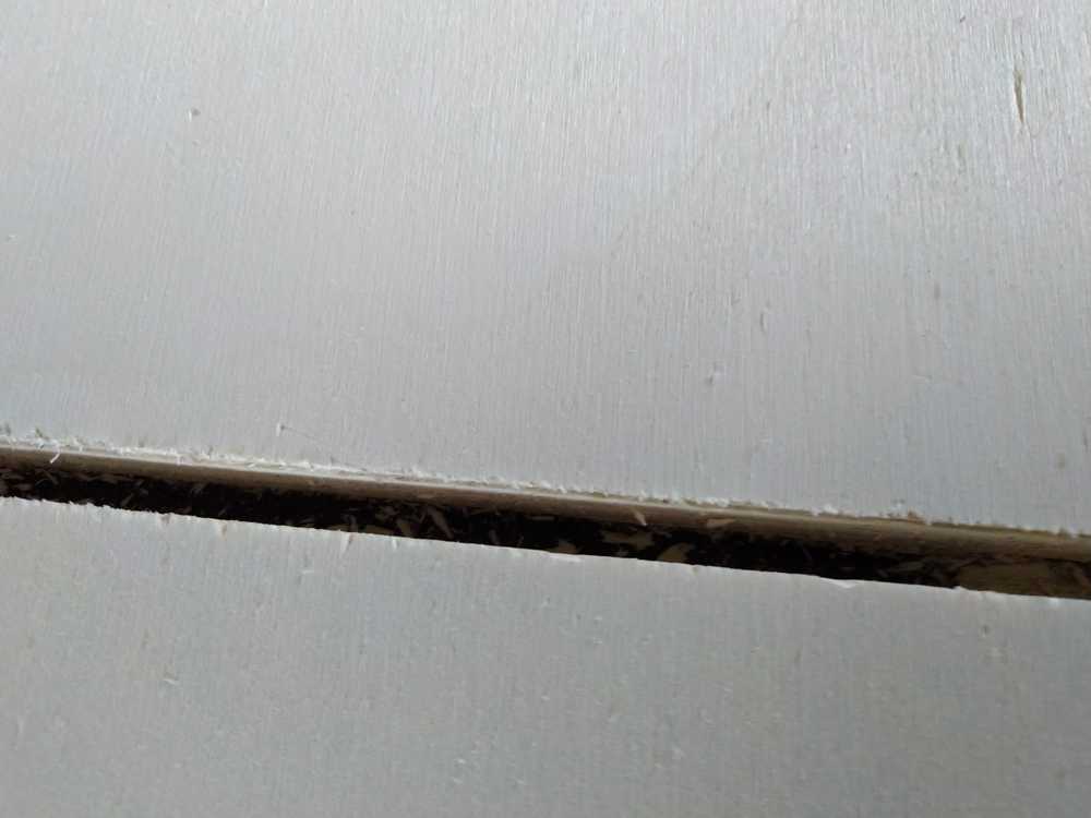
I run the job again. After trying 12.9mm 13.1mm the final setting is 13.3mm. When you need to stop je job you just press the space bar. Shopbot will ask whether you want to quit or resume, etc. Press quit. Turn of spindle and dust sucker. Adjust your settings in V-Carve. You can than just run the job again. The Shopbot remembers the X and Y. Don’t turn Shopbot or the software of as it will forget X and Y. Normally that is not a problem if you have written down your X and Y settings. But since Shopbot currently does not know its own origin, leave Shopbot on.
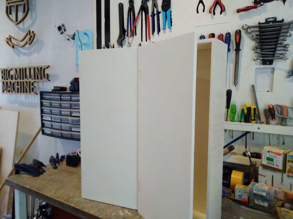
press-fit cabinet
Cut the wood.
Parts
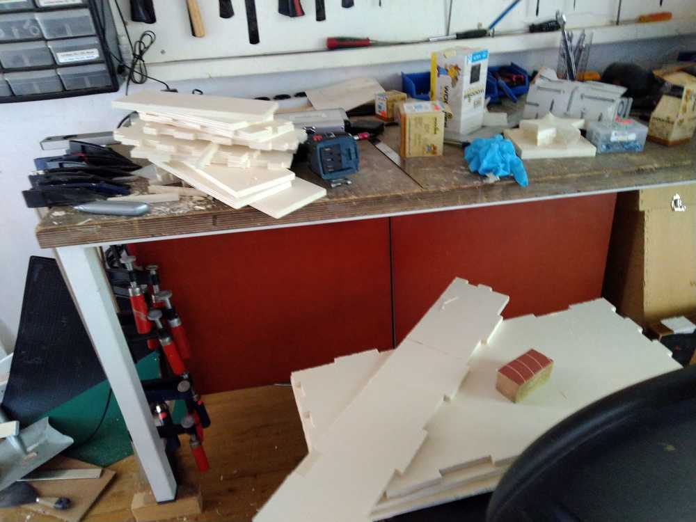
Press-fit!
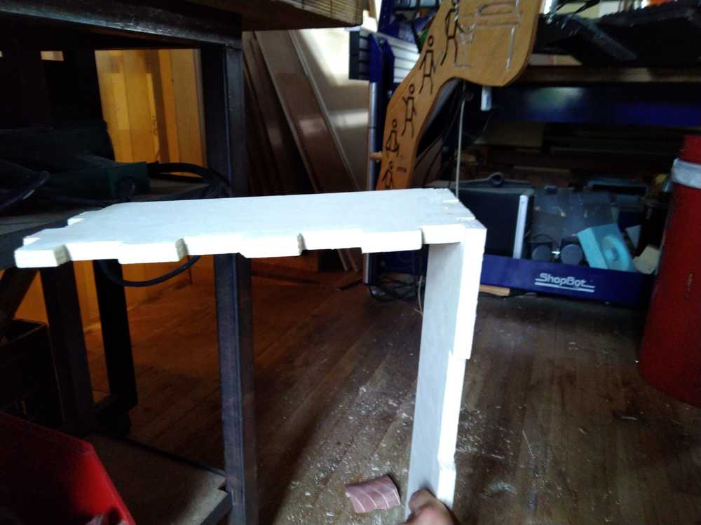
No glue.
Used all of the wood as per the assignment.
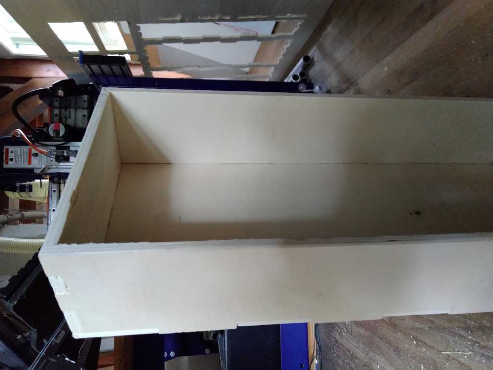
Final result: so press-fit it can hang on the wall.
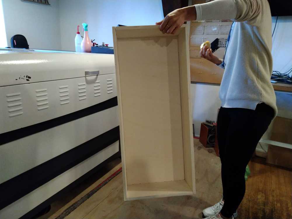
With door attached.
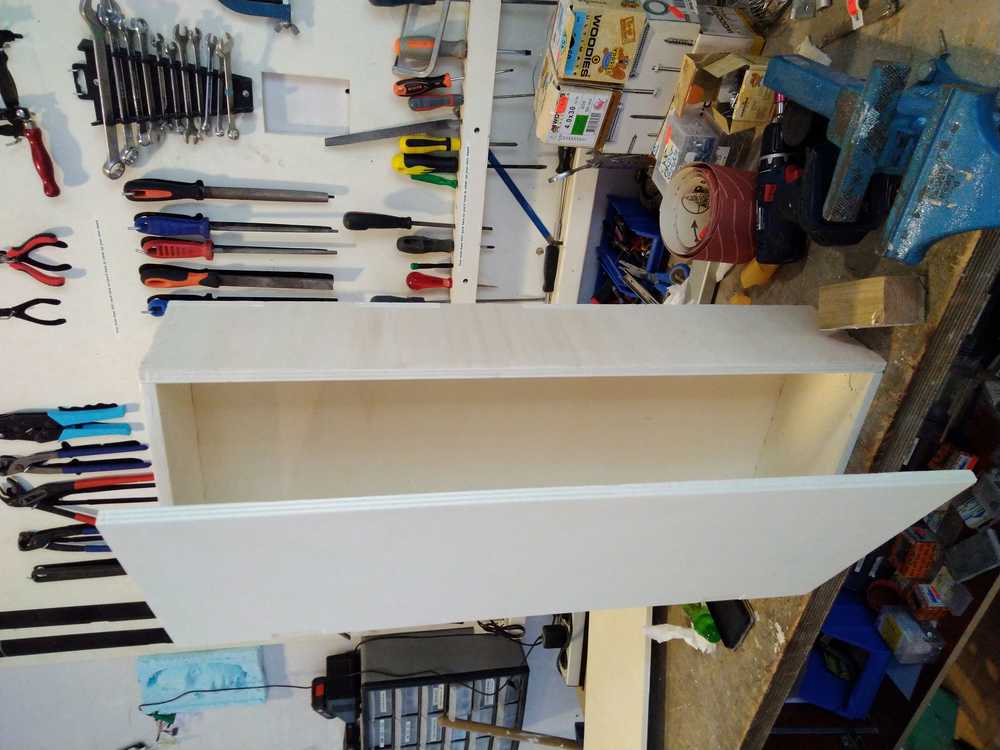
Two finished cabinets.
Global lecture
Assignment: Make something big: design it, mill it and design it.
Types of wood:
Sanded plywood / veneer plywood. Looks nice and is strong.
OSB. Is cheap, nice for because it uses al parts of the treee. Less structutal integrity than plywood.
Milling versus drilling > Milling has sharp edges at the sides. Not just downward like drilling.
Fewer flutes for rough milling. More flutes for finer work.
Flat end mill gives flat bottom surface.
Speeds and feeds
Chip load. Flutes: each pass of the flute takes a bite. Chip load is how much each tool bites in: range in inches 0.001 - 0.010.
Cut depth is how far between passes. Diameter of the tool is equal to cut depth.
Stepover: about 50%. You can vary step over trading time against surface finish.
Lubricants: help with heat transfer. But you won’t need it.
Fixturing: how to hold your stock down.
Vises: type of clamp.
Bar clamps.
Screws: one of best ways. Don’t mill where the srews are.
Making curvy things:
Flexures: can’t do it in OSB
living hinges
kerfing
steam bending
wacky wood
Reciprical frame construction. Parts that depend on parts.
Toolpath:
kerf, offset, runout: Account for the kerf with the offset.
Runout: wobbly tool, path is larger than the size of the tool because it mills wobbly.
conventional, climb: conventional for roughing, climb for finishing.
rough/finish cuts: First rough then finish.
high-speed, dry, ramping, adaptive clearing, swarf, rest, trochoidal
one-sided, two-sided: flip over the stock and mill the other side.
2, 2.5, 3, 4, 3+2, 5 axis
cut depth, clearance, collisions
Press fit has to be done by dog boning. You cant make 90 degree anges
First mill in the air before doing it for real.
Protoype: Make little prototype and make sure it comes together nicely before starting on the bog project.
CAM: viewing files before the go to the machine. Slicer tool for milling.
Roland: .rml Shopbot: .sbp Most common: .g code. .ord
Measure cutout: Take tool diameter cut. And measure how much thicker is the trace Test how square you can measure. (As in 90% is hard with milling.) test in z > are sides vertical when you make a cube? speeds and feeds > you need it for your machine and your stock. Not forbidden to use nails. But it is nice to make something reversable: put it together and put it apart again.
http://archive.fabacademy.org/2018/labs/fablabakgec/students/ashish-sawhney/week8.html
- Cutting a chunk of material is good enough to diagnose all issues with the machine, e.g. a small square of wood.
- Take a piece of stock, make a shallow cut, a deep cut, go slowly, go fast/quickly, and see how the machine responds to find that sweet spot where you are working as quickly as possible, but the machine is happy, and look at what happens if you go too fast, or too slow.
- If you cut out a square, one is, are these dimensions the dimensions you asked for? One is, are the top, bottom, right, and left dimensions the same? But one of the questions is, if you look at the space that was cleared, how does that relate to the size of your tool? What is this material removed vs the tool size, and that’s a measure of the imperfections in the machine.
- Take your machine, cut a small square. See how the dimensions relate to what you designed. Check the runout of the machine. Check going fast and slow, small cuts, big cuts. See what it looks like to get it right and wrong. You can experiment with toolpaths that aren’t just a straight line but some of these high speed toolpaths. The following tests were performed:
- testing kerf and runout: The tool isn’t a perfect straight line, it has some degrees of freedom in the collet, and the collet might also not be straight. So, the reality is your tool wobbles a little bit, jiggles around as it goes around, and so runout is the actual diameter of what’s cut. If what’s cut is larger than the diameter of the tool, it is because of imperfections in how its held in the collet. And so, one of the things you have to test is the kerf and the runout. To test for runout, we cut holes at 6 different cut depths (Figure 8.1), and measured their inner diameters. The data is as follows (Table 8.1):
Recitation Debugging
Francesco:
Important: writing
Describe environment: What software are you using. Especially when you are looking for help.
What are you doing and what are the results. You can write this down in a table or in another form.
Important: reading
Debugging is all about understanding.
RTFM: Read the F manual.
TL;DR: Too long did not read is not an option
Purisism will not fly: If you need to solder an ugly wire to your board to make it work: do it!
Duaa:
Always do a physical check
If you created a PCB and hooked it to your programmer and it does not work, there are too many options. You need to narrow it down.
- Try it on another computer.
- Make sure the IC and the pin header are okay.
- If your programmer is not showing up when
- LED does not light up: check that part of the programmer.
Therefore you need to know what each part of your device
Nicholas:
Tools:
When debugging electronics you are blind. Use tools to see something. Multimeter will solve 90% of your problems: Check continuity, voltage.
Continuity: do the signals go where they are supposed to go. Put it on continuity test and test if the current is going where it is supposed to go.
Measure voltage: 200mV, 2V. Do you have the amount of Volts you expect. Do you need 5V but get 3.5V.
Check all components with the multimeter.
Logical analyzer: when you need to check the signals. Cheap and small devices. Saleae, Pulseview. All you will see is low or high.
Oscilloscope: will show you everything. High sampling rate. There are many parameters. triggers, time level.
Basic using of oscilloscope. basics of using an oscilloscope - blink. Data shown on the oscilloscope has already happened earlier. It is sort of a time machine. You can stop and freeze the signal and go back in time. How long does a button press take. You can use the cursor function to get an exact reading.
When everything seems to work but it behaves differently. show an external signal on code execution.
In circuit and on-chip processing. You can put in the firmware some points: break points: allows you to pause execution.
USB does it work. lsusb under Linux. Power on USB is usually 5V but communication is 3.3V.
Radio communication: use DVB-T receiver as radio tool.
Salaea logic 16 clone with open source software.
Global review
Many Labs want to help. A lot of FabLabs who make respirators
Putting together a group of leaders in respitory health. They caution: a bad ventilator is worse than no ventilator.
There are projects they need urgent help with.
Projects need to be coordinated.
Tab FabLab network to produce globally.
Experts were worried about the inability to respond from manufacturers. Open fabrication can get around limitations of manufacturing.
Impact on the class
50% of Labs are now closed. We will continue. We can stay pretty close to the original schedule for now.
The next couple of weeks can be done from home. April 22 is the first Lab heavy.
If you do not have access to any equipments you can work with simulation.
Let the network know if you need help of any kind due to the pandemic. As a network we have a huge amount of (distributed) resources.