5. 3D scanning and printing
Amsterdam, February 26, 2020
To do
| Description | status |
|---|---|
| Design an object that could not be made subtractively | Done |
| Print the 3D design | Done |
| 3D scan an object and optionally print it. | Scanned yes. Printed no. |
| Group assignment: test the design rules for your 3D printers | done |
| Document my part of the group assignment | Done |
| Document my individual assignment | Done |
| Work on final assignment | Partially done |
Source files
| Description | link |
|---|---|
| 3D design of robot | Downloadable zip |
| the OBJ. file of 3D scanning is large so it is hosted externally on Sketchfab.com | https://sketchfab.com/3d-models/hand-3d-scan-d1b351ec2a254905aadc42f14f16f84f |
urls
| Description | link |
|---|---|
| Index of this week’s topic | http://academy.cba.mit.edu/classes/scanning_printing/index.html |
| Global lecture video | https://vimeo.com/394033225 |
| Global review video | https://vimeo.com/395859651 |
| Recitation Disability video | https://vimeo.com/394968691 |
| Group assignment documentation | https://fabacademy.org/2020/labs/waag/groupAssignments/week5.html |
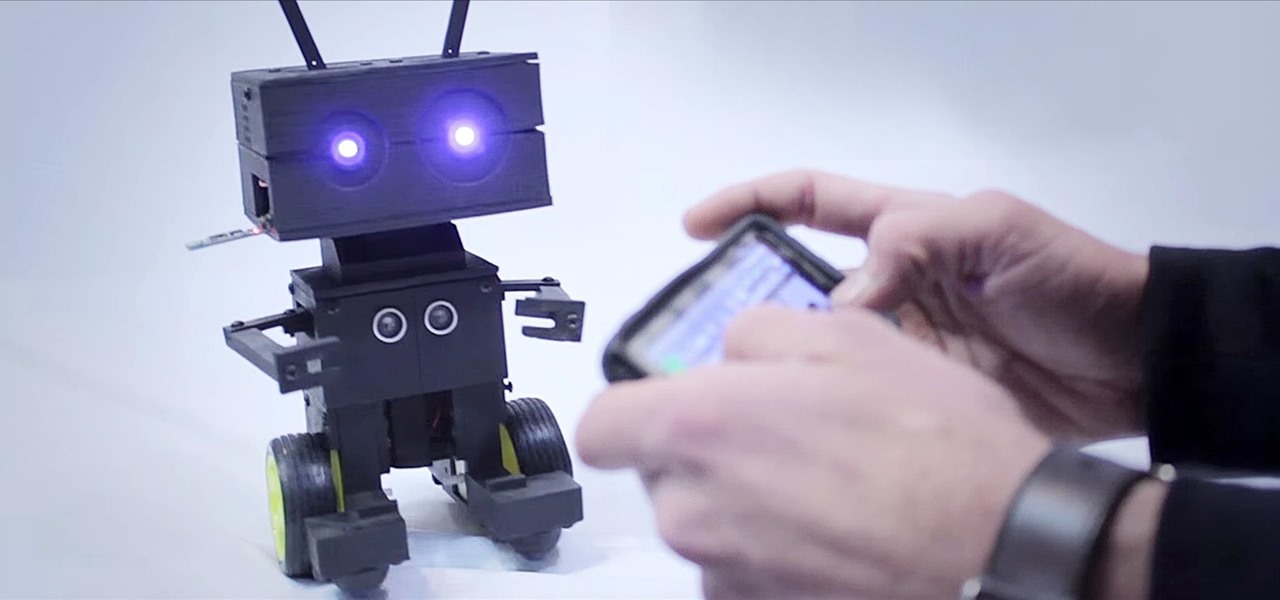
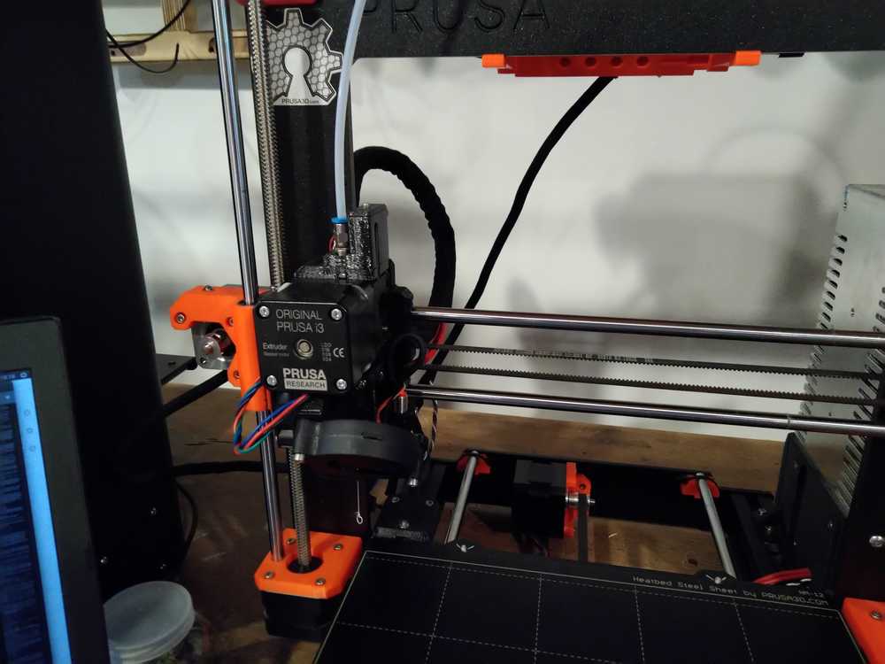
The Prusa MK3S printing my robot.
3D printing
We have four kinds of 3D printers: Two Prusa’s, the older i3 mk2S version and a newer i3 MK3S verion, an Ultimaker 2+ and a Printerbot. The Prusa’s are open source. The Ultimaker was conceived of in a FabLab in Utrecht.
Software
To make the design for your 3D model you can use FreeCAD and other kinds of design software. Then export your project as .STL or .OBJ. This must then be loaded into slicer software that will slice the model into slices. There are different slicer software programs such as Cura and Prusa. Cura is from the Ultimaker but has limited options. I am going to use the Prusa software which is open source and has more options.
Rutger gave a short introduction to the Prusa software. Prusa will slice the model and translate it into G-code. You must add your printer to the software.
 Add your printer to the software. When you export the G-code it is very important to select the right printer model.
 Import an OBJ or STL file.
 Click
Click slice to have the software claculate the slices. With a slider you can check the different slices the software has created.
There are several ways to give your model support:
- Raft: The raft is a base added to the bottom the object. From simplify3D.com ‘Rafts are primarily used with ABS to help with warping and bed adhesion, but they can also be used to help stabilize models with small footprints, or to create a strong foundation on which to build the upper layers of your part.’
- Skirt: The skirt is an outline around your object that does not touch the object. It’s the first thing the printer makes. It helps to ‘prime your extruder and establish a smooth flow of filament’. Source:
simplify3D.com.
- Brim: a more extensive skirt. ‘Brims are often used to hold down the edges of your part, which can prevent warping and help with bed adhesion.’ Source: simplify3D.com.
- Infill: You can add supporting material to the inside of your structure. 100% infill means the model will be solid. Often 5% - 10% will be enough. The printer will add a latice work on the inside of your model.
- Supports. You can have the slicer software add supports to parts of the model that ‘float’ in the air. These supports are added during printing to add support and can be taken away after the print is finished and cooled down.
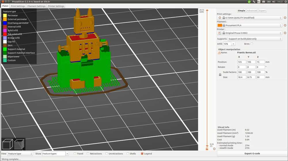
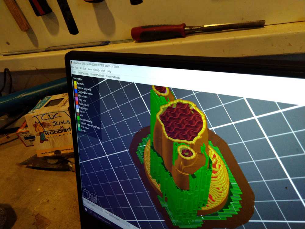 Image of infill and supports in Prusa slicer software. The colors on the left of the screen are a legend of what every color means. Brown-red is the infill. Green are supports.
There are many different settings in the slicer software. It is advised to look at some tutorials to explore all the different possibilities. Here are the settings Rutger discussed.
- Printer settings: Setting Ultra will print very precise but is very slow. Often Optimal is good enough to get a good result.
- You can define the thickness of the outside layer.
- You can add one or more of the supports described above.
- You can choose to have your first layer printed differently than the rest of the model. For instance more slowly to induce better bed cohesion.
- You can topple your model if that is a better way to print it. When printing the letter ‘T’ for instance, you might want to print it down on its back rather than standing upward with added supports.
When you are finished with preparing your model you export it as G-code. You save it on an SD-card. All printers but the Printerbot accept the SD-card for file input.
Machines
We have four(!) 3D printers at our disposal for this week.
The printerbot is operated by connecting it to your computer and steering the machine via Cura. Or you can connect it to a Raspberry Pi and steer the machine via a webinterface.
The Prusa i3 MK2S is an open source 3D printer. It is an older model and a little quirky. It has an 0.8 mm nozzle instead of 0.4 mm like the other printers. It makes more crude models but is faster. If you use the printer for prototyping it does a good enough job.
The Prusa MK3S This is a newer Prusa model and prints far more precise than the MK2. It is easy to operate and open source.
The Ultimaker 2+ is a 3D printer conceived of in a FabLab in Utrecht. At over 2000 euro’s it is more expensive than the Prusa MK3 which is around 800 euro’s. It prints slowest of them all. The square casing around the printer is nice because it makes it easier to transport.
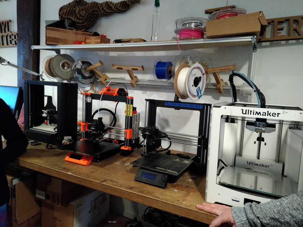 Left to right: Printerbot, Prusa MK2S, Prusa MK3S, Ultimaker.
Filament
There are different types of fillament. We use PLA because it is biodegrable and cheap. It is made of corn. The heat needed for PLA is 215 degrees. You can have a margin of between 210 and 220 degrees. We also have filament that produces a wood-like structure. But we don’t use it because it clogs up the nozzles. All filaments need a different temperature. You can change the settings on the panel of the printers. When you are done with the machine remove the filament from the nozzle.
 Filament is stored in boxed underneath the printer bench.
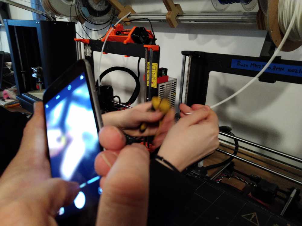
To add filament to the printers, first cut it into a sharp pointy ending. Then lead it into the filament hole of the nozzle head.
This is pretty straight forward for all four printers but the Printerbot. Here you need some serious prying and pushing.
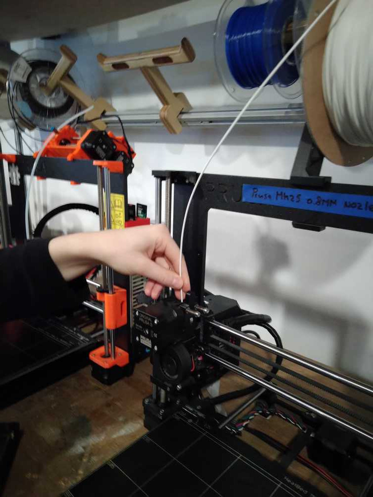
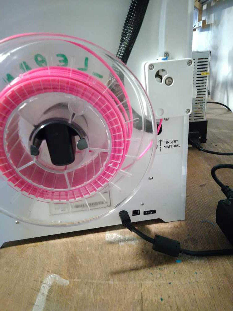
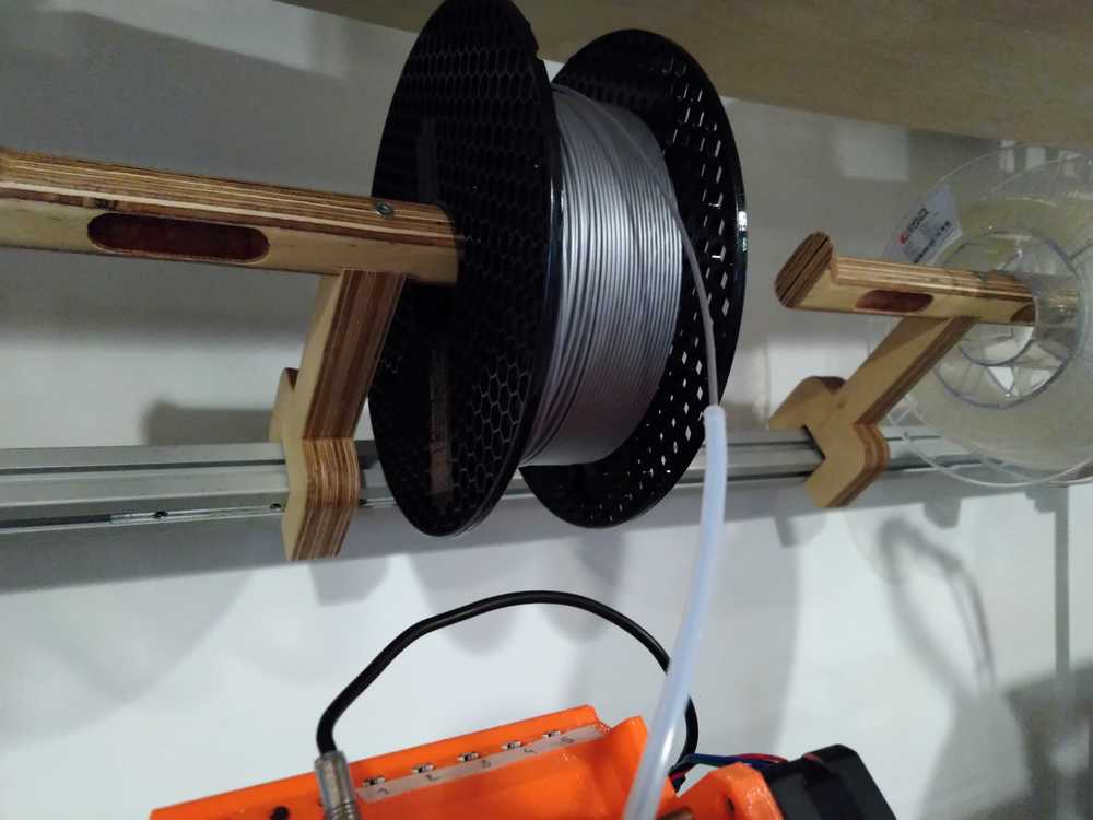
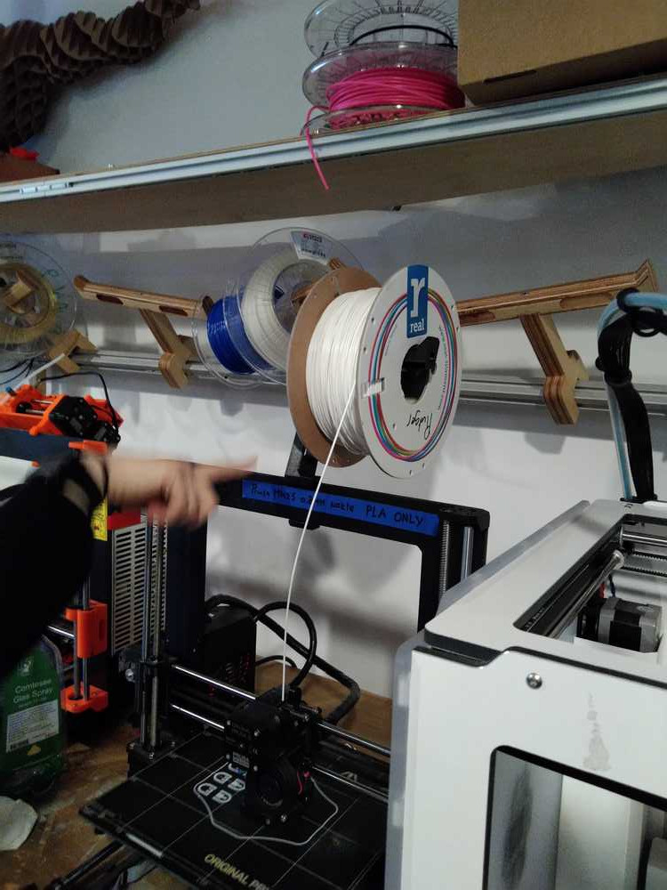 Make sure the filament role isn’t obstructed. It must be able to easily turn around its holder to keep on feeding the filament into the head during printing.
Operating the printers
Make sure the beds are leveled. The Prusa’s do this themselves. The Ultimaker needs to be manually leveled at times.
Clean the bed before and after use with conventional glass cleaner spray.
The printers work with three axis X, Y and Z. The Prusa’s move the nozzle head in three directions. The Ultimaker head moves X and Y. The Z axis is operated by moving the bed up and down. When you have to remove your model van de printer bed, let the bed cool down for more easy removal.
Operating the Prusa MK2
Clean the bed.
Switch the MK2 on with a switch on the right back side of the machine.
Press the round button on the printer’s panel twice.
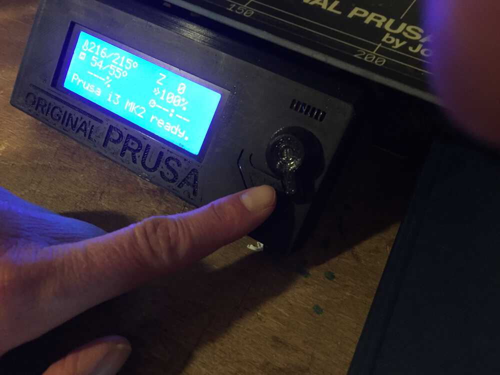 The control panel. The round button can be clicked and turned. Below the round button is the reset button.
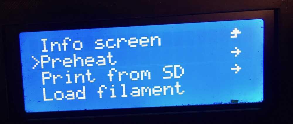
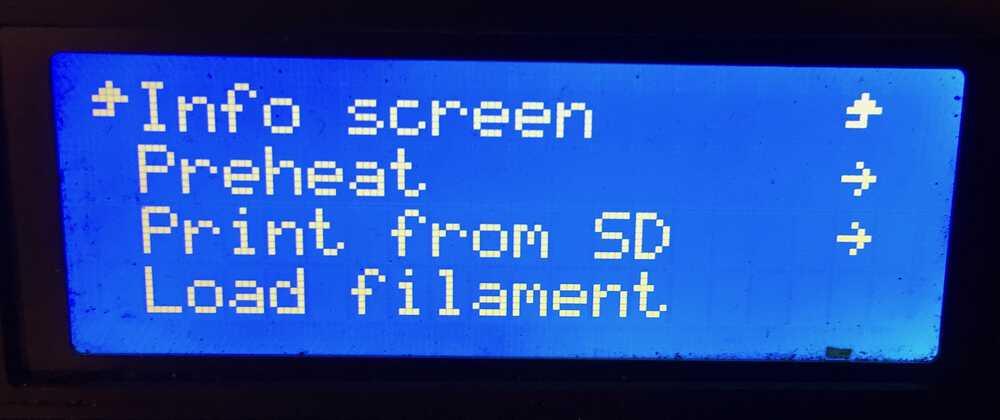
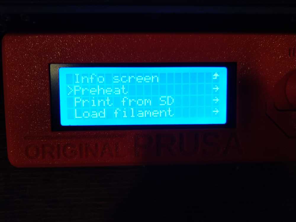
Turning the round button let’s you scroll through the menu.
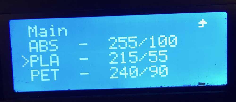
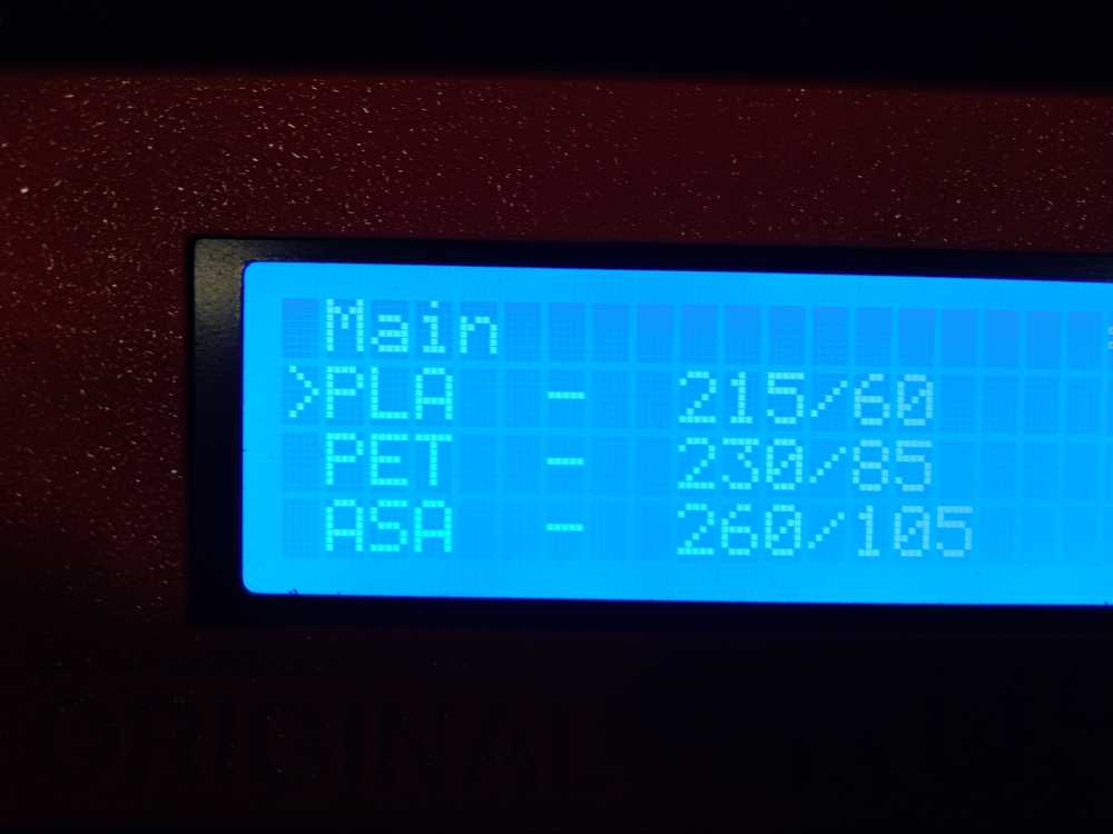
Scroll to preheat, click the round button, then scroll to PLA and click the round button.
If the heat is not the way you want it you can tune it manually with the tune menu item.
When it is done heating up, manually add the filament to the printer head.
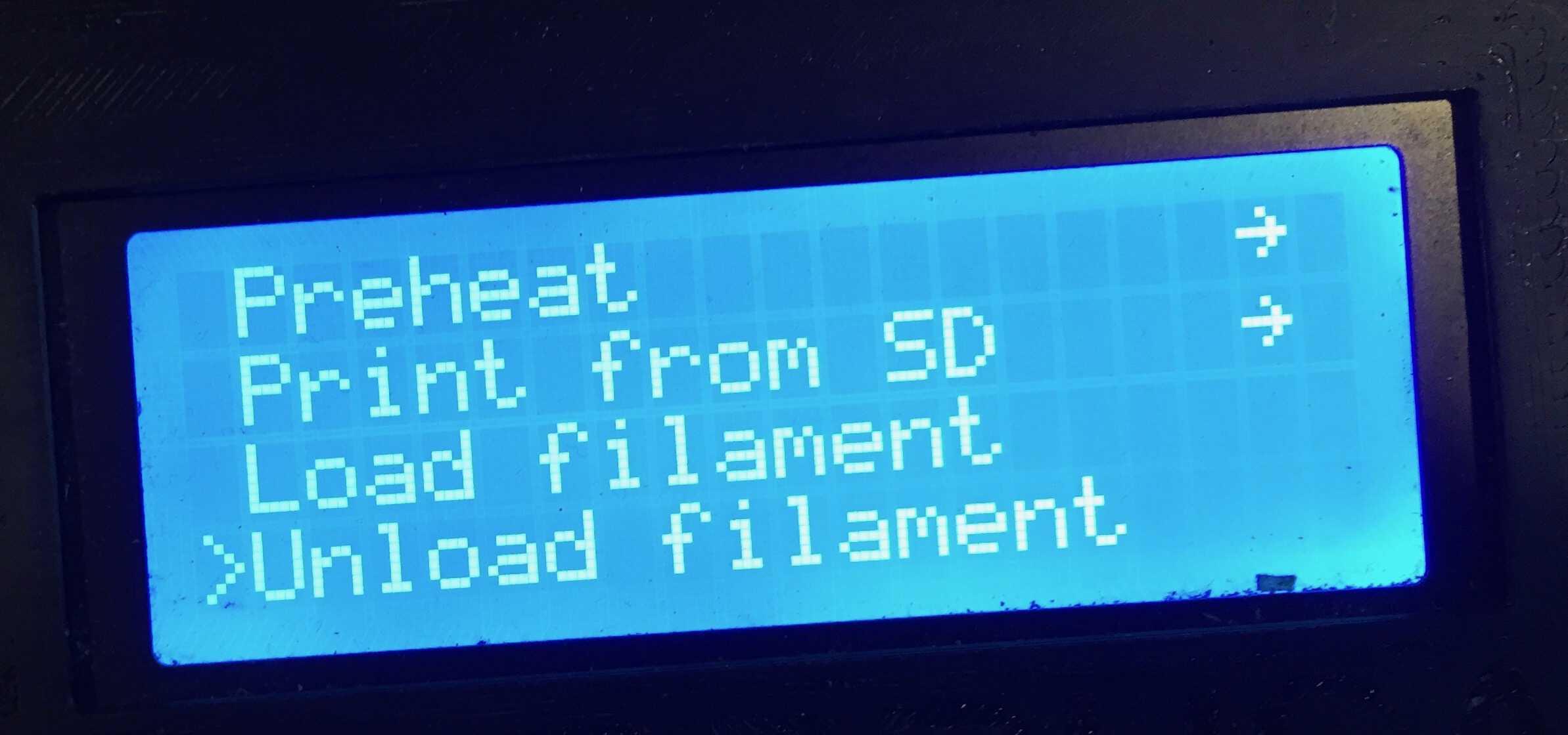
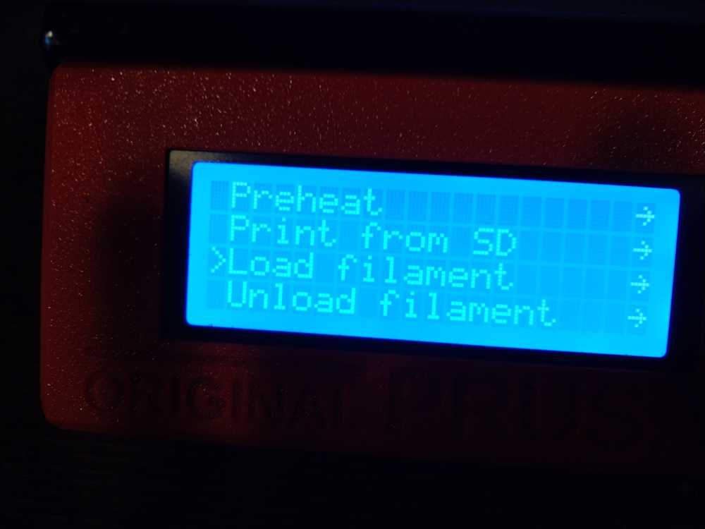
Scroll in the panel’s menu to load filament.
After a while the printer asks if the color is clear. If so click yes.
Load the design from the SD card. In the menu scroll to print from SD.
Scroll into the right directory. Make sure you have selected your file (this works a little unclear. make sure the little arrow points at your file, not the directory). Press the round button.
The MK2 is a little quirky. Sometimes it does not want to load from the SD card on the first try. In that case press the reset button and try again.
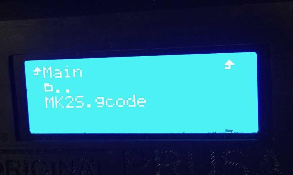 In this picture the file is not selected. You must scroll until you see a little marker in front of the file and then press the round button.
If all went well the printer says it is callibrating. When it is done it will start printing. Check the skirt is being printed okay. Keep an eye on the printer during the printing of the first layers. If something goes wrong you can pauze or stop the job on the printer’s control panel.
When the job is done, wait for the bed and the object to cool before removing.
Unload the filament.
Switch off the machine and clean the bed.
Troubleshooting
If the layer line is too thick and not sharp, the nozzle is too close to the bed. You can manually adjust it in the control panel by adjusting the Z-axis.
At the website simplify3D.com there is much information about possible causes for misprinting.
Operating the Prusa MK3S
Operating the Prusa 3 works the same as the Prusa 2 with that difference that it is even easier to operate. It has no quirks and needs no resets during operation. A detailed description of it’s workings is given under the individual assignment chapter.
Operating the Ultimaker 2+
The Ultimaker needs different filament than the other printers. It needs 2.85 mm. It is loaded in on the back of the machine.
Enter the SD-card and press print choose file in the menu.
Operating the printerbot
The printerbot switches on with a button on the back of the box (not the printer part of the machine). It is operated via a Raspberry Pi and a web interface. Or directly from your PC using an USB cable. Make sure the Raspberyy Pi is powered on. The website address is written on the printerbot with sticky tape. You can load your design onto the website & slice it there as well. You can add add-ons to the website if you want extra features in the software.
Operating it through your laptop is done through the Cura Slicer software. You may need to add the printer make and model to the software. You can add an extra module to the software to operate the filament from the computer.
The bed works differently. It is not a clean bed but has a papery sticky tape on it. If the filament doesn’t stick well use hair spray or pritt stift (a type of glue) to make it stick better.
Group assignment
3D printing: testing the printers
A full description of the group assignment can be found on our communual page.
The group assignment was a lot of fun again this week. It started with an explanantion by Rutger about using the software. Followed by an explanation about using the printers by Michelle. Both are described above.
The group assignment consisted of making a test model on all the 3D printers to test the difference in their performance.
Harm found a test file on thingiverse which I will not include in this documentation because it is over a megabyte in size. He then added it to the Prusa slicer software. The most important thing was to add our printers to the program. We had some trouble figuring out the exact name of the Prusa MK2S in order to add the right printer. The Printerbot might be even worse its name is hard to find on the device. I would advise all device makers to add make and model clearly on the casing.
Rinke and me set to work on the Prusa MK2S. I like this machine, it’s open source and a little erratic. It has character. We’ve described how we operated the machine on the group documentation.
Comparing the test models printed by the different 3D pinters showed a significant difference. The MKS2 was clearly the least capable of producing details in the model. The MKS3 was the most capable printer. It made sharp corners and walls and passed almost all the tests the best.
The Ultimaker performed less well than I expected. It took the longest time to print the model but wasn’t nearly as detailed as the MK3. It also started messing with the time. It started out needing over three hours. As it was working it climbed to over eight hours. In the end it took about as much time as it has first indicated, but it was a little disconcerting to see those estimated times keep on climbing up.
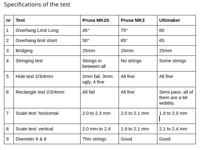
Here is the table with the outcomes of the test.
And some of the pictures detailing the outcomes of the test. They’ re more pictures on the group assignment page.
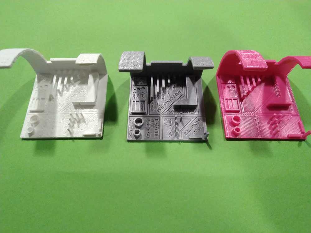 Left to right: Prusa MK2S, Prusa MK3, Ultimaker 2+.
 Left to right: Ultimaker 2+, Prusa MK3, Prusa MK2S.
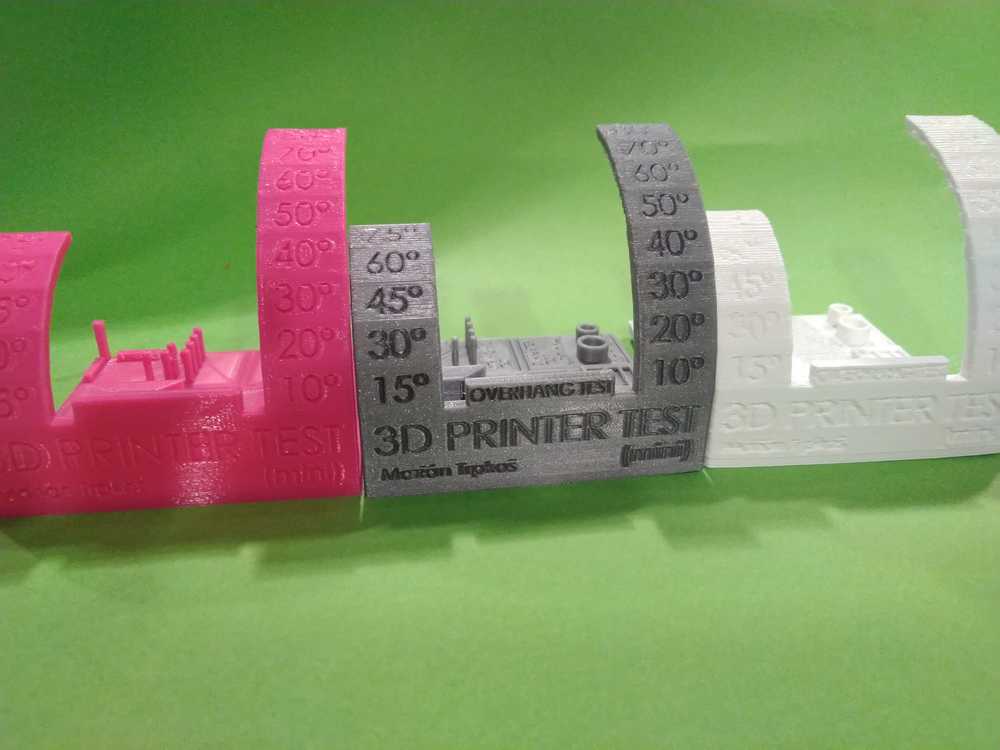
 Overhang test of the MK2S. This printer had the worst performance on all tested features. The overhang starts deteriorating at 45 degrees for the long overhang and at 50 degrees for the short overhang. The MK3 which performed best, reached 75 degrees and 65 degrees respectively. But it is a nice little machine with character and it is the fastest.
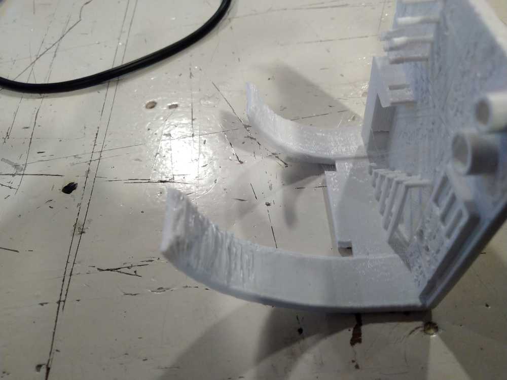
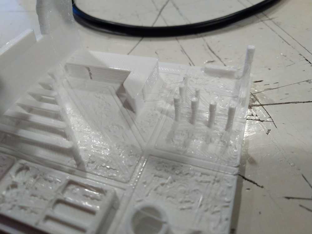 String test of the MK2S. It is not very well visible in the picture but there are thin strings between the little poles on the upper right of the model. The MK3 passed the string test with flying colors. The Ultimaker did better than the MK2S but did have some strings.
The MK2S has a 0.8 nozzle as opposed to the others which have an 0.4 nozzle. This shows as it has trouble with details. The lettering that is clearly readable on the MK3 is an unreadable garble on the MK2S.
String test of the MK2S. It is not very well visible in the picture but there are thin strings between the little poles on the upper right of the model. The MK3 passed the string test with flying colors. The Ultimaker did better than the MK2S but did have some strings.
The MK2S has a 0.8 nozzle as opposed to the others which have an 0.4 nozzle. This shows as it has trouble with details. The lettering that is clearly readable on the MK3 is an unreadable garble on the MK2S.
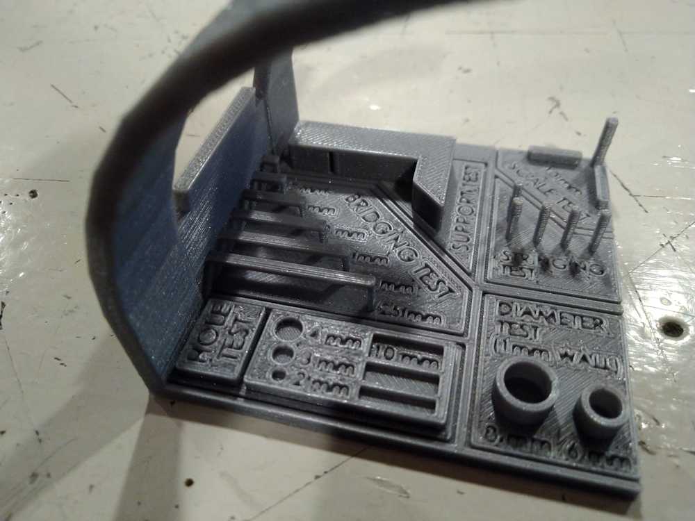 The MK3 performed best on all tested features. The lettering is clearly readable. No strings between the poles.
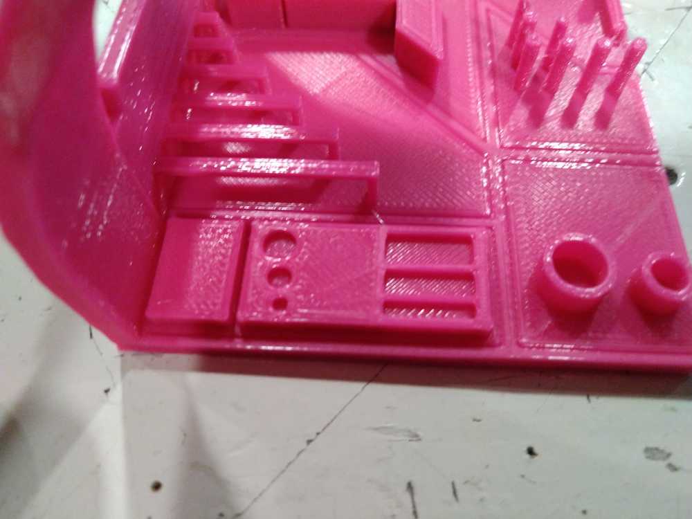 The Ultimaker is the most expensive of the three models, looks the fanciest and takes the longest time to print the model. But it does not perform as well as the MK3. Here you see the rectangle test. The corners and the walls aren’t nice and sharp but a bit wobbly.
3D Scanning
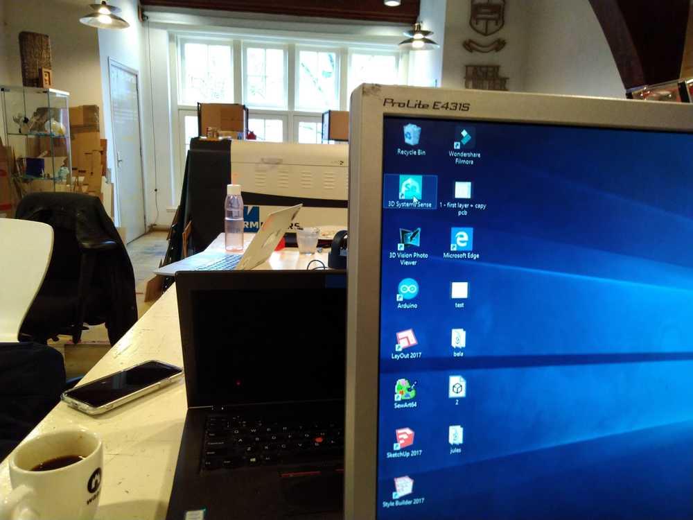
The hand scanner is quite affordable at around € 500,- and is of quite good quality. The scanner is in the closet at the back of the lab. Always put it back after use. It can only be used at one specific computer which is on the table island in the middle of the lab.
Just plug in the USB cable into the computer and run the 3D Systems Sense software.
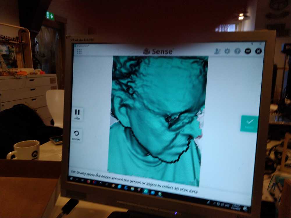
You can scan objects and people. Beware that scanning transparant objects is difficult. You need to add some reference points to the object. To start scanning press Scan in the software. It counts down and starts scanning.
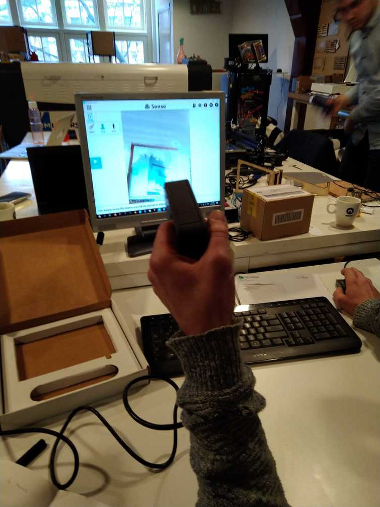
There will be a green banner if the scanning goes well. Red means scanning did not go well. You can simply go back to the last reference point when the banner was still green.
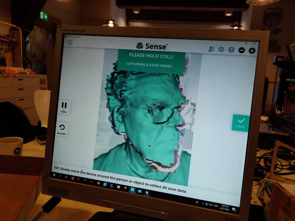
In the image you can see that the object may contain some holes. Go back with the scanner to remove as many holes in the image as possible. When you are done you click finish.
You can then modify the image with functions like trim. Pressing solidify will fill up the holes in the image of the scan. Your model needs to be solid.
When you are done you can export the model as an OBJ or STL. That file can go straight into slicer software.
Check if the model has the right size. The shape is almost always correct but the size may sometimes be wrong.
Individual assignment
The individual assignment for this week is
- design and 3D print an object (small, few cm3, limited by printer time) that could not be made subtractively
- 3D scan an object (and optionally print it).
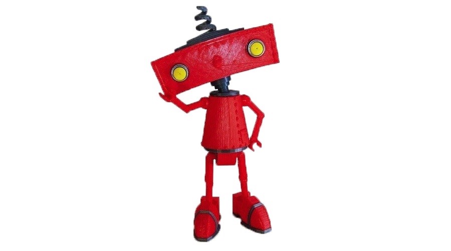
For our assignment we need to make a model that can’t be made substractively. Running holes in different angles through your design is a way to do that. Maybe something along the lines of the whiffle ball I made in week 02. But searching the internet for some inspiration I saw people had 3D printed little robots and that seemed like something nice to make.
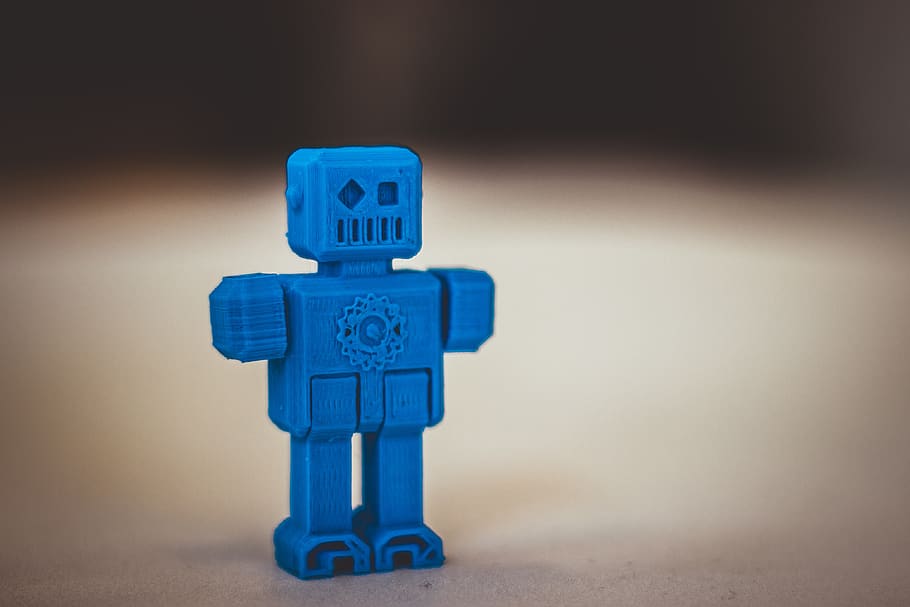
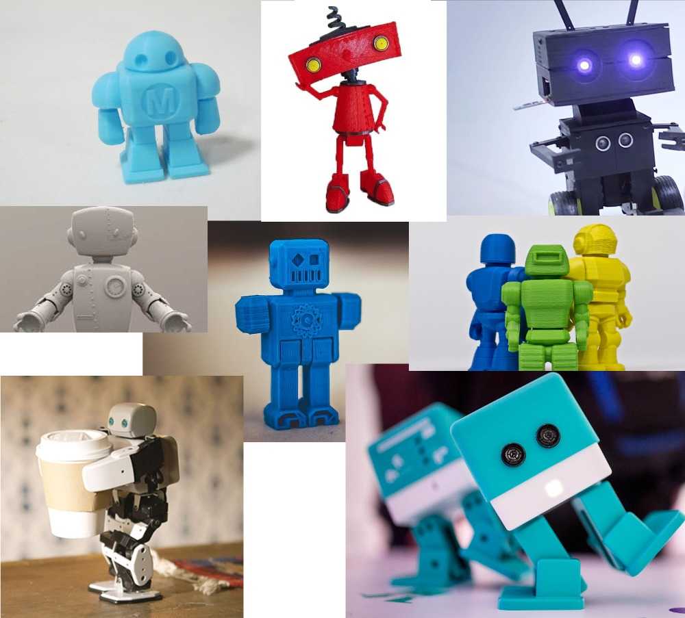 I look online for some inspiration. The sources of the images light blue robot, bad robot, light-eyes robot, white robot, dark blue robot, robot set, coffee carrying robot, zowi robots.
Design
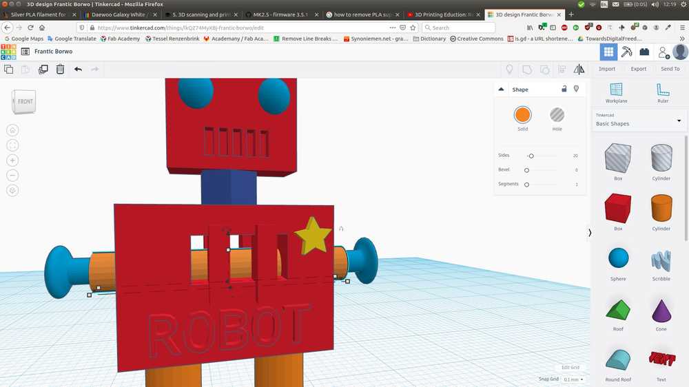
I thought about making something in FreeCAD but I am also interested to see what other design software is out there. So I looked online what software is available. The first that came up is TinkerCAD from Autodesk. So I went to have a look at that. It looks supereasy to use and even has a premodelled robot in its librbary (I am not going to use that though).
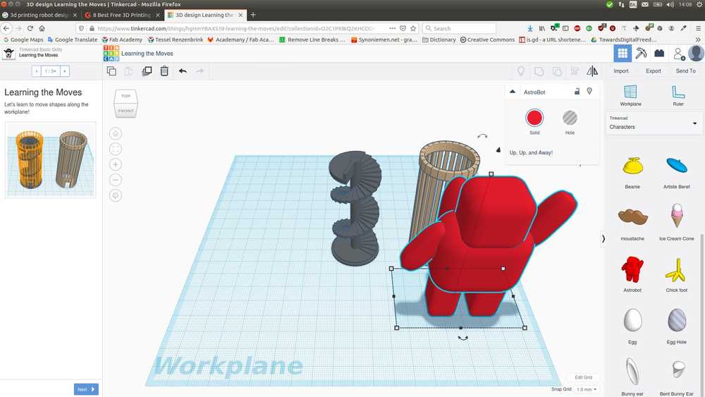 A premodelled robot that I am not going to use.
TinkerCAD is operated in the browser. You need an account to use it but Autodesk asks very little of you. Only an email address. The program starts with a little tutorial, six basic moves such as how to rotate the plane, how to move an object, resize it, etc. The learning curve of TinkerCad is almost non-existant. In that it is the opposite of FreeCAD. But it is also quite limited. After a few hours modelling the robot I reached the limits of the program. It was interesting to see a different program, but next time I’m going back to FreeCAD. There was an interesting realization though. TinkerCAD uses the same principles to make a design. You build up a model by adding and manipulating different elements. The user interface is much easier but in the end you need to pre-conceive your model the same way as you would in FreeCAD. By doing TinkerCAD and thus not having to battle with FreeCAD’s steep learning curve, gave room in my head to understand the design process better.
I then made a sketch for my own robot.
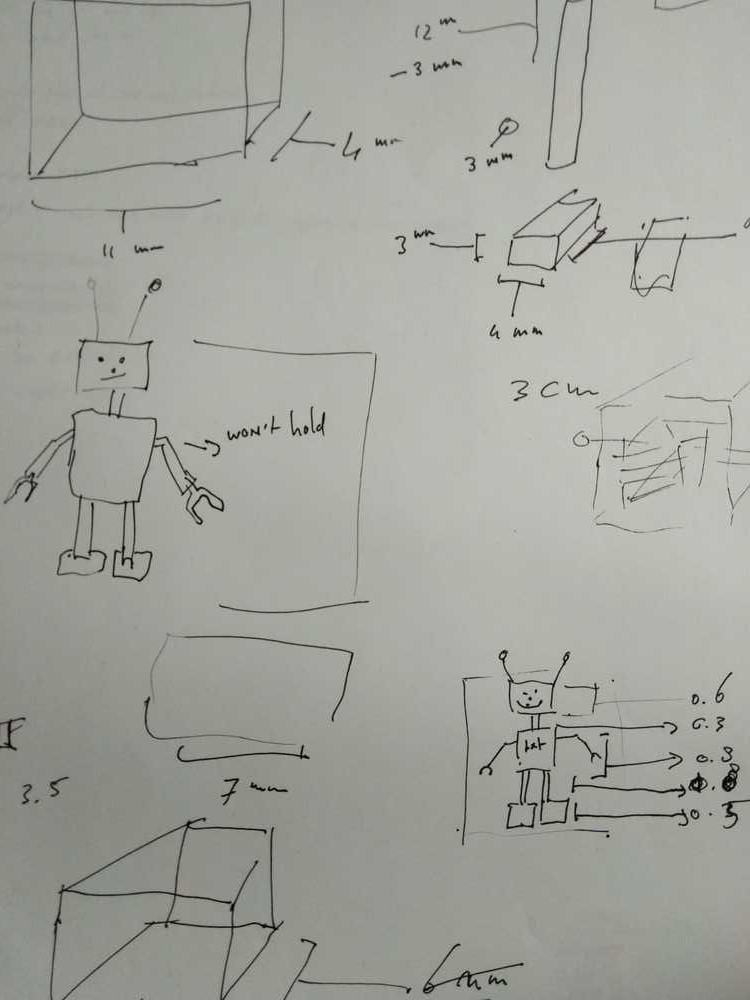 Sketch.
At first the sketch only consisted of a drawing of the robot. I started designing in TinkerCad deciding on the dimensions of each element just by looking at the visual representation on the screen. I realized that is not a good way of going about it. It is better to decide on the dimensions for each element with more consideration. For instance, how big do the feet need to be to carry the rest of the model. On the sketch paper I started adding measurements on the go. Drawing a foot and adding dimensions. Next time it is better to decide on all this in advance. To fully draw your model on paper including dimensions and only then go to the software.
I want my robot to be about 3 cm tall. I had to look up online what measure units TinkerCad uses. You can choose that in the grid section in the right corner at the bottom of the screen. The default is millimeter.
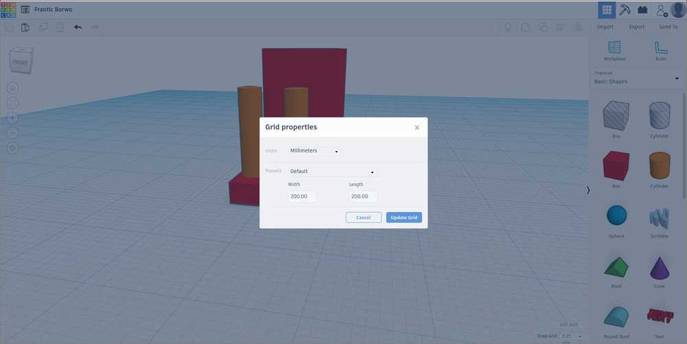 Default measuring unit is mm.
When you click on an object dots and arrows appear around it. These refer to length, rotation and orientation parameters. You can just click a few and see which is which.
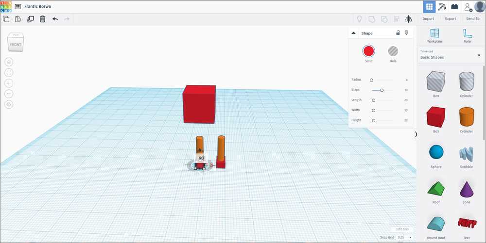 Here the X-axis rotation parameter is selected. You can either drag the change rotation or fill in a different number in the measurement window.
On the left side of the screen are the view options. The circle with the house in it lets you see the entire model. The circel below zooms on on an selected element. Below are zoom options but using the scroll wheel on you mouse works really well for zooming. Clicking the right mouse button lets you rotate the workplane. When working from a touchpad press CTRL to move the workplane.
 View options.
Moving an object over the Z-axis gave me a little trouble. It took me a little while to figure out it is the top arrow that appears after selecting the element. It seems it does not always work the same. Sometimes clicking it will give you the number window. Sometimes you just have to click it and start dragging it up or down. It was one of the very few things that took some time to figure out. The other one was alignment.
Having some trouble lowering an element over the Z-axis. The solution is to click the black arrow at the top until the Z-axis measure line appears. The Z-axis behavior is a little erratic. The z-line does not always show up. You can try just pulling it after clicking the black arrow.
 To move an element over the Z-axis click the top arrow. Either pull the arrow or click a few times to have the number window appear.
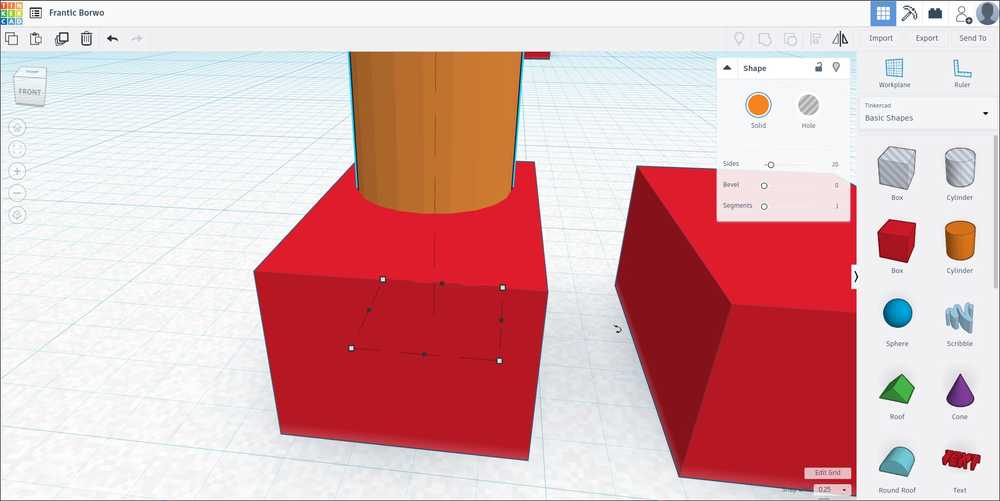
Just like FreeCAD an element can be solid of a hole. For making the robot’s mouth I added narrow blocks to its face. On the right top side of the screen you can choose the element to be solid of a hole. Then select the element you want to cut out and the element you want to cut it out of. Selecting multiple objects is done by pressing the SHIFT key while selecting with your mouse. Then click the GROUP icon, on the top of the screen above the solid/hole window. The volume of the elements that are holes are now removed from the solid element you selected.
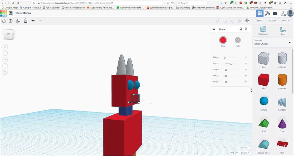 Removing volume by using the Hole tool.
The only other thing that took a bit of figuring out was the Align tool. Select to elements by holding the SHIFT key. Then press the Align icon at the top right of the screen. Multiple lines and circles appear. When you hover over a circle, an orange representation of one of the elements appears. This shows where the element will be moved to if you click that circel. I found information about aligning on Instrutables
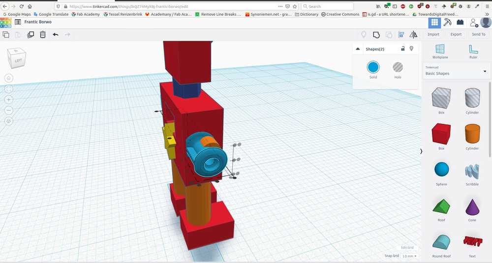
The assignment stated that we had to 3D print something that can not be made substractively. Therefore I changed the chest of the robot. Instead of a solid chest it has a hole in its chest with a grill in front of it. Behind the grill a cylinder is placed. The cylinder is an axil pole to which the robots arms are connected, like the axis pole in a car on which the wheels are connected. Because there is a round pole behind a grid, this figure can not be made substractively. The drill or knive good not go beyond the grill to drill the cylinder. I was working on the model at night and could not think of a way to add a feature that would make it impossible to make it substractively. I decided to make a new design in FreeCAD, a whiffle ball type of thing. But when I woke up in the morning the chest-grid idea came to me when standing in the shower. So it is good to let some things simmer for a while before starting over.
 Creating a hole in the chest.
 Aligning the pole to the arms of the robot.
 The chest grid with the pole visible behind it.
I decided to add some text because I am curious how it will come out in the printer. It does mean I’ll have to use the Prusa MK3 because the MK2S will not be able to produce such detail. On the front I wrote ‘ROBOT’ with lettering that is extruding. On the back ‘HUMAN’ is written in lettering that is holed out. The ROBOT text sticks out .5 mm, the HUMAN text indents 0.5 mm. Writing that down I’m wondering if that is enough…
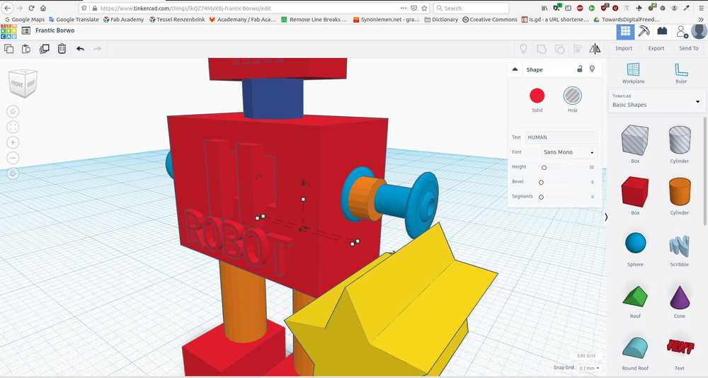
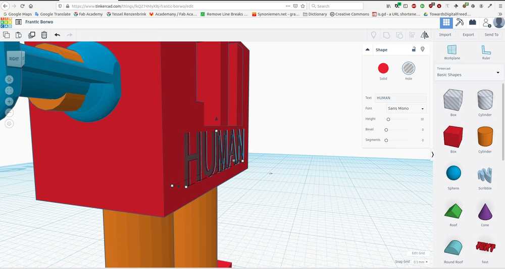 Together the words make ROBOT HUMAN like the Robot Rock / Oh yeah song by Daft Punk.
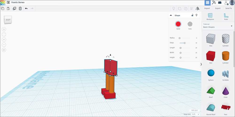
I decided to enlarge the feet of the robot to give it more surface to stand on. If you want to enlarge the by 1 mm but want it to go 0.5 mm on both sides: first select the left block of the length parameter and add 0.5 mm to the element. Then select the right block and add 0.5 mm.
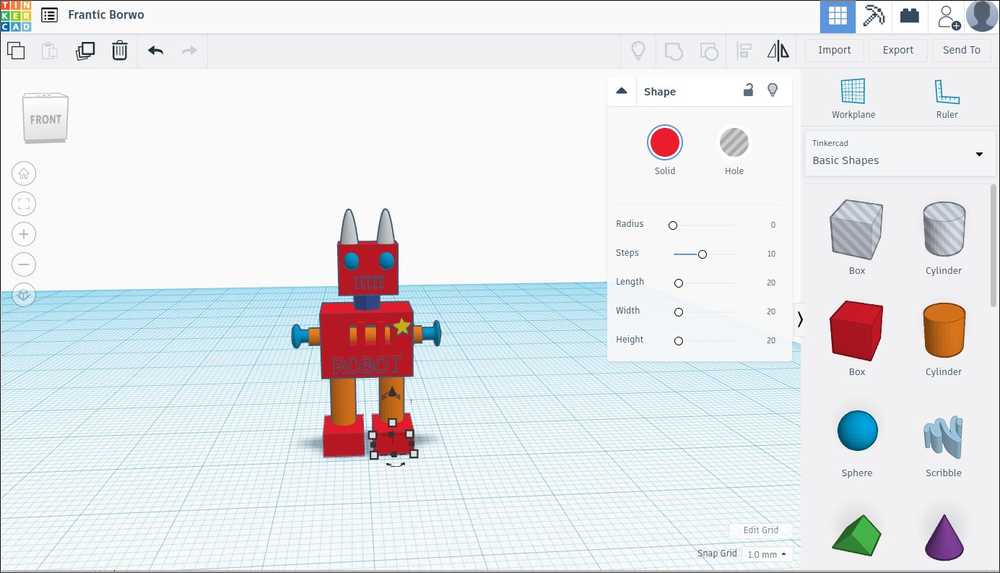 Enlarging the supporting surface.
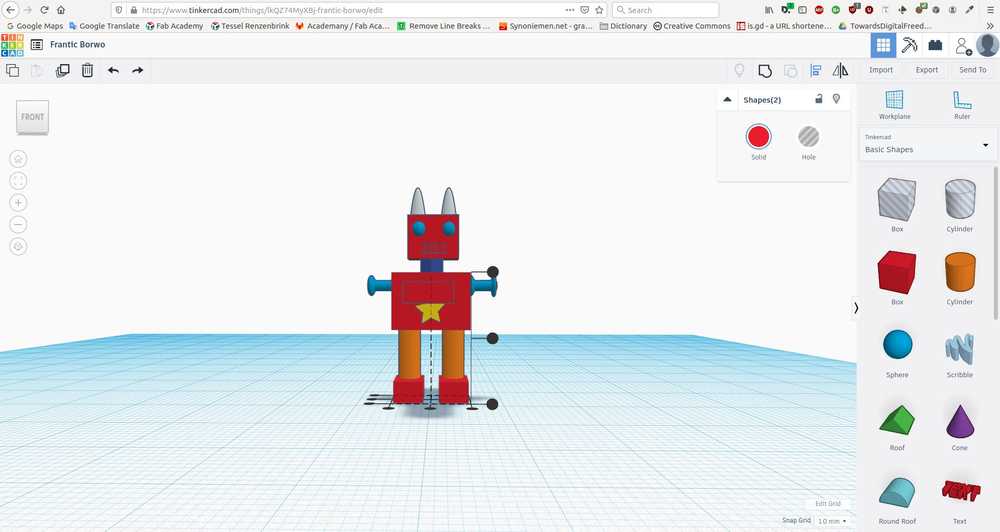
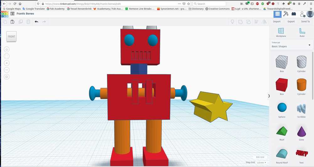
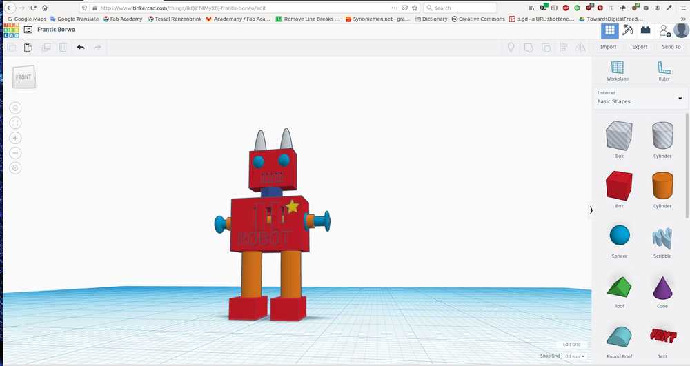 Finished design front.
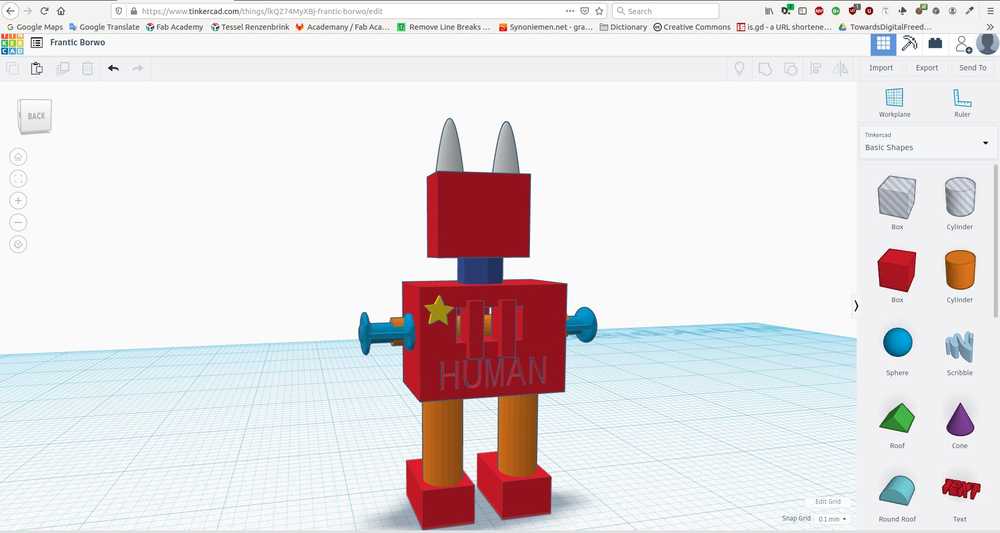 Finished design back.
I exported the design both as an OBJ and an STL file. According to matterandform.net the two type files are very much identical. The both take the geometry of a surface, and render them as a point cloud. The geometry is now rendered as many dots. Then these dots are meshed together by drawing polygons of the points.
The difference between the OBJ and STL is that OBJ also exports the surface detail of the design. So if you would scan an apple and export it as OBJ, the file contains information about the color of the apple. STL only retains information about the geometry of the object. The design will therefore be rendered in gray scale. There are good explanatory pictures in the website referred to above. I will not display them here because I do not know their copyright status.
Since I am not interested in retaining the surface texture, I will use STL in my slicer software. I suspect STL will be a lot smaller file size than OBJ. But I am wrong, the STL file is 789 kB while the OBJ is a little over 500 kB. I’ll import them both in the slicer software to see the difference.
Slicer software
I am going to use PrusaSlicer. I went to download the program from prusa3d.com. Was redirected to github where I downloaded the Linux AppImage. The application would not open at first. I had to click properties and tick the ‘allow execute as program’ box. Then the program opened and started with a wizard for initial configuration.
Note: To open PrusaSlicer go to: FabAcademy/classes/class05/3D-design/PrusaSlicer and click on the AppImage. Can’t open it from the command line or the software finder.
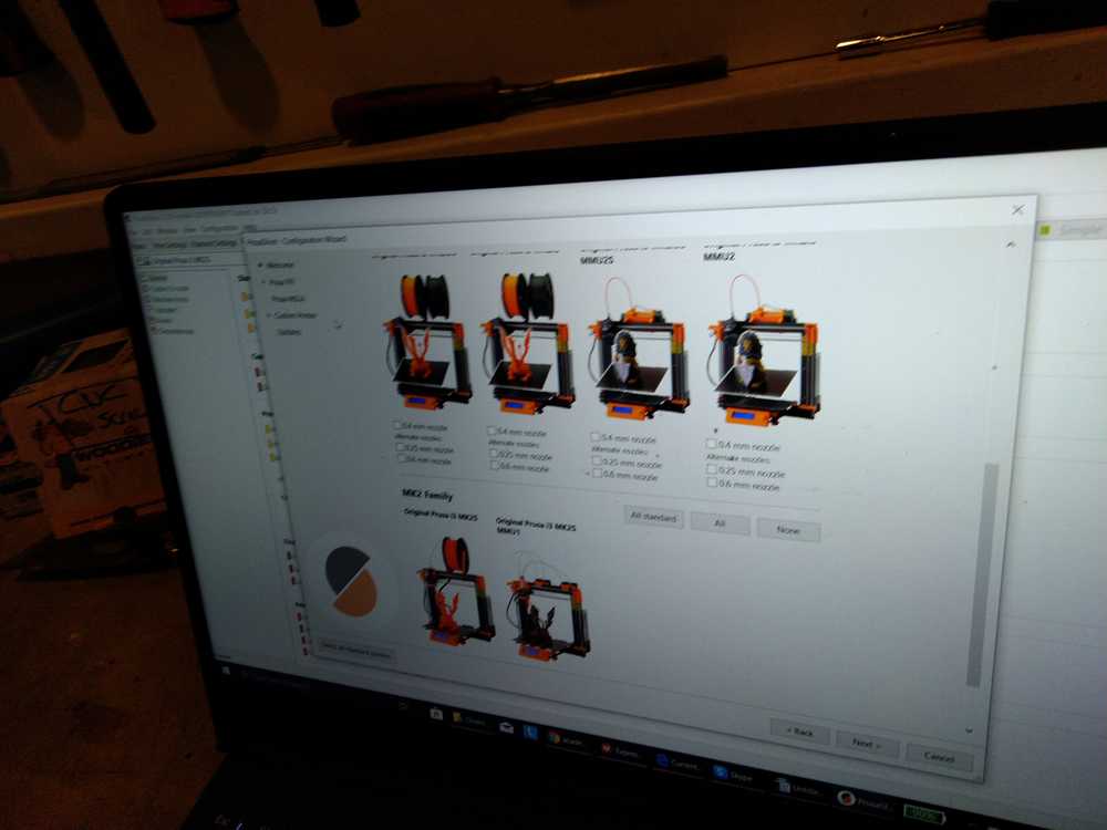
The Wizard lets me add all the Prusa printers of my chosing and different filaments.
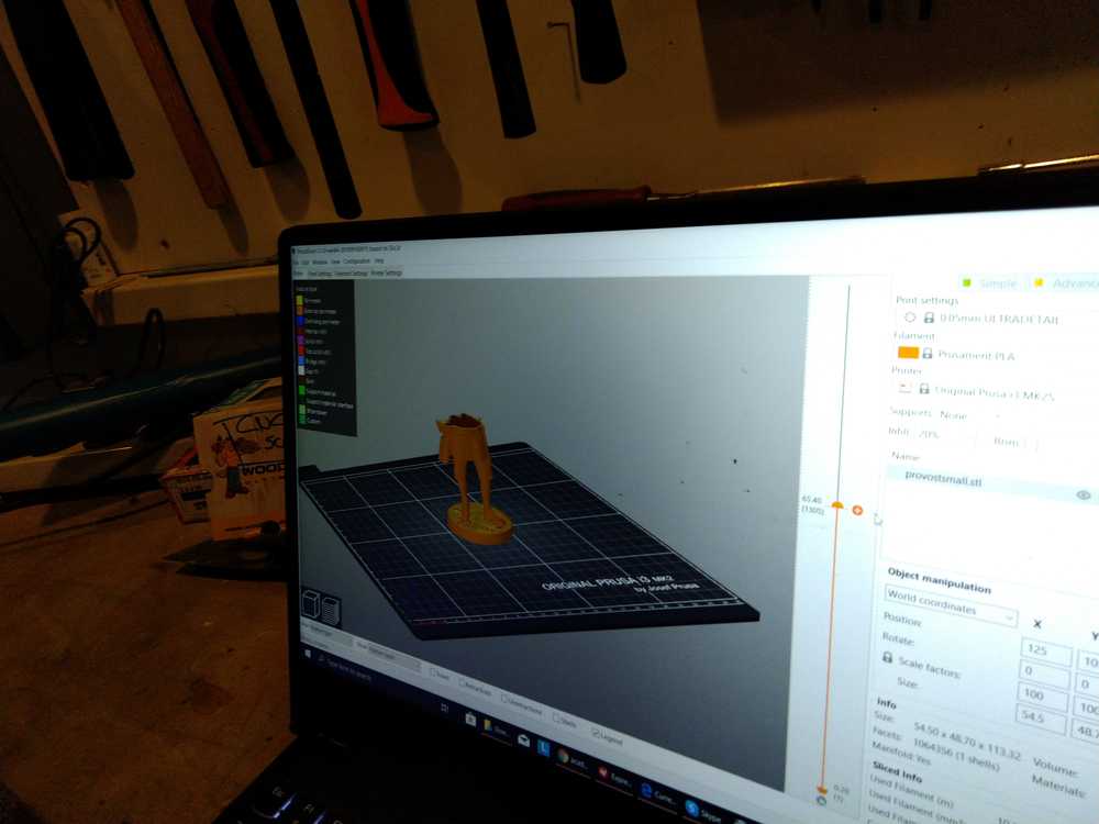
Then I can start in PrusaSlicer. I begin with selecting the Prusa i3 MK3 printer. The MK2 won’t be able to provide enough detail for the design I made. I search online what the different settings mean.
Printer settings Source: slic3r.org.
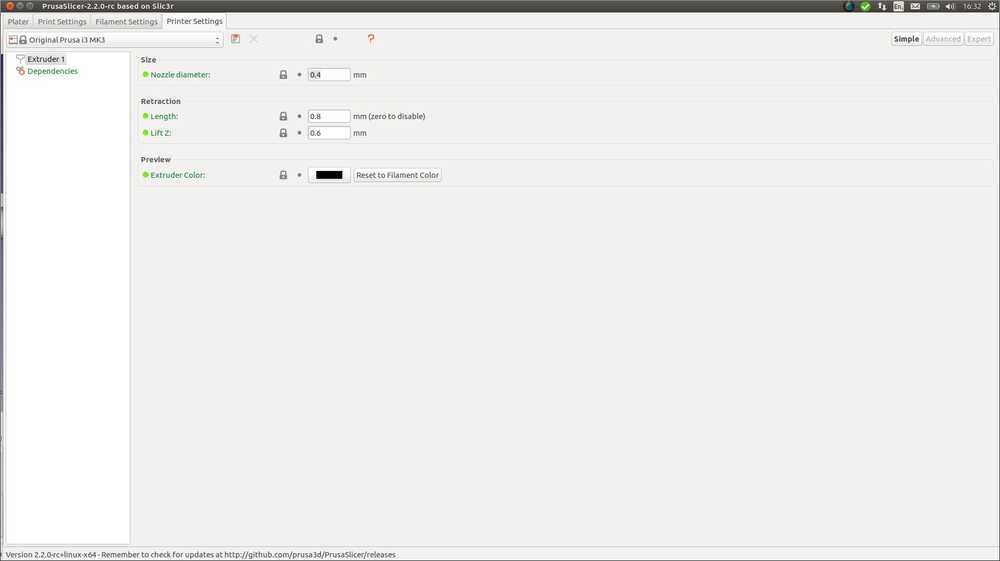
Nozzle diameter: we went over that on Thursday, it’s the measurement of the nozzle. The MK3 has a 0.4 diameter.
Retraction: Tells the printer to pull back the filament between extrusion moves. The filamant will ooze from the nozzle, therefore you need to retract i order not to have it drip on the model. A value between 1 and 2 mm is recommended. However, default setting is 0.8 mm. I am going to leave it at that for now. Length is the number of mm it will retract. Lift Z raises the entire extruder on the Z axis by that many millimeters during each travel.
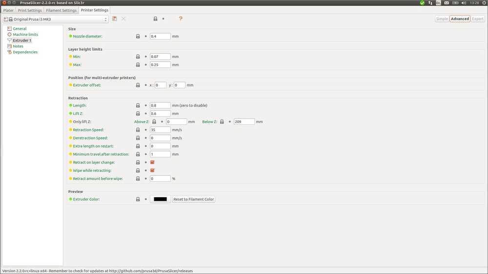 The window has Advanced and Expert windows. On the source page linked to above all these settings are explained. But I am going to leave these settings as they are for now.
Filament settings
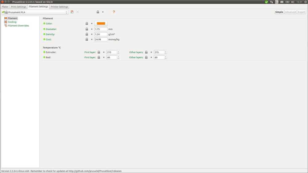 Here you can define the parameters of the filament. I am not at the lab right now so I don’t know those yet.
The temperature for PLA filament is 215 degrees, that is right. I’ll check tomorrow if the bed should indeed be at 60 degrees.
print settings Source for all the information below: prusa3d.com
At the top is a dropdown menu with the print setting. Default is set at 0.15 mm Quality. Rutger explained this. This will give you a good detailed model but also a faster printer. When you go Ultra detail it will be more detailed but also very slow to print. I leave it at default.
Layer height: thickness of each layer/slice. It is the main factor affecting print time and vertical resolution. Taller heights will speed up printer time. Lower heights will give you extra detail. This is interesting since I have details of .5 mm. The default layer height is 0.15 mm. I think that should do for sufficient detail.
First layer height: A thicker first layer will improve adhesion to the bed. I leave it at the default o.2 mm.
Vertical shells:
Parameters: Defines the minimum number of outlines that form the wall of the model. Recommended minimum is 2. PrusaSlicer calculates a recommended parameter based on your model.
Spiral vase: Creates a continuous single outline container, gradually increasing the Z height. Not relevant for my current model.
Horizontal shells:
Solid layers: The bottom and top part of each model is usually filled with solid layers (100% infill). You can set how many top and bottom layers you wish to print. Default is set to 7 for top and 5 for bottom.
The next Tab is Infill.
Fill density: The precentage of filling in the model. 100% is solid. Default setting here is 15%. The webpage notes: ‘The strength of a model is mostly defined by the number of perimeters (not infill). If you want to have a stronger print, increase the number of perimeters.’
Fill pattern: There are many different patterns. Default is Gyroid but you could go honeycomb, stars and many other choices. Prusa choses Gyroid as default because it: ‘Gyroid is one of the best all-round infills.
It's 3 dimensional - giving it equal strength in all directions
It can be printed fairly quickly
It doesn't cross itself in the same layer
It has good strength/weight ratio
(We think) it looks really neat
‘
Top fill pattern: allows you to make a custom fill pattern that is only visible on the top layer.
Bottom fill pattern: same thing for the bottom layer.
The next Tab is Skirt and brim.
Skirt: define brim’s distance from the object.
Brim: define brim width.
The next Tab is support material.
PrusaSlicer detects when your model needs a support. (You can’t prit mid air). In this tab you can specify that you want supports to be autogenerated. Which I will leave on. Thanks PrusaSlicer.
Plater tab
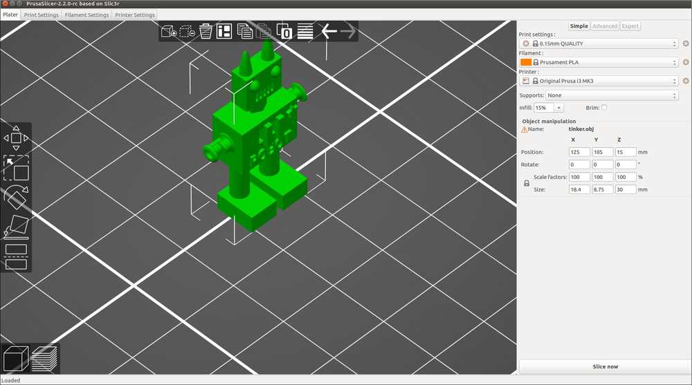
Here we can import the model and start fooling around with it.
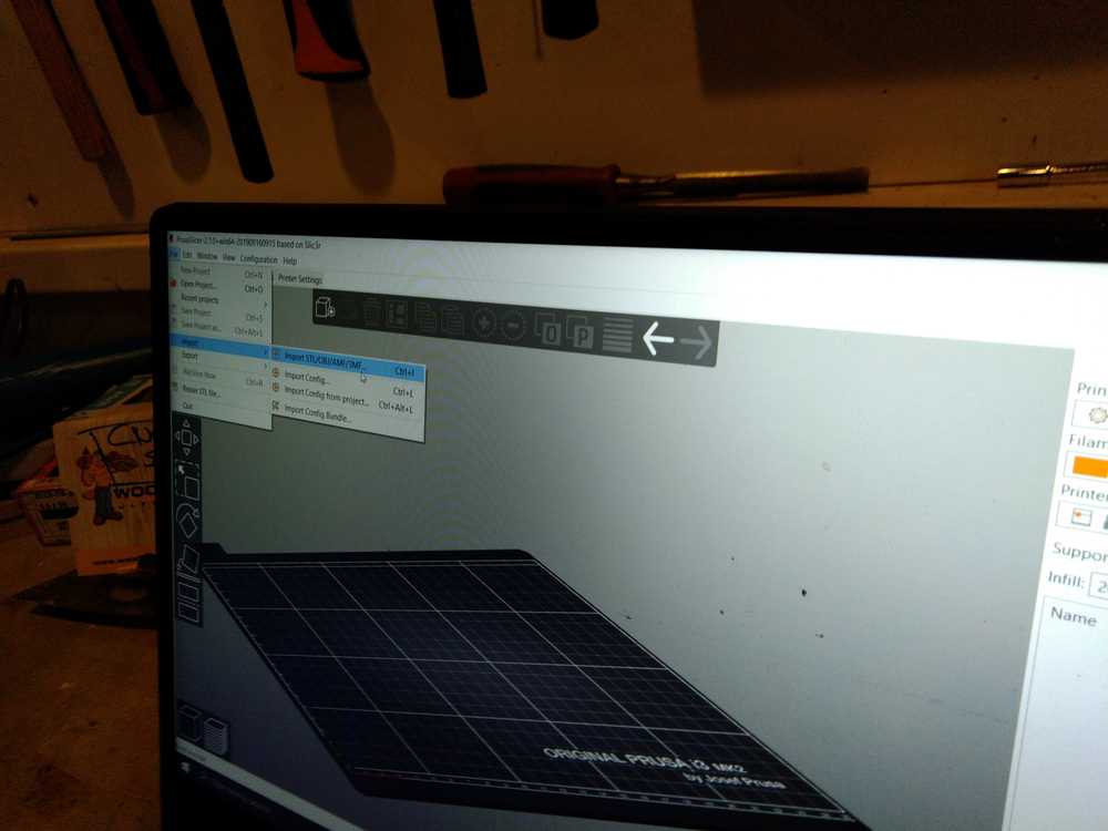
File > Import to import the model.
 OBJ file extension. The surface texture as was seen in TinkerCAD is not imported. Contrary to the explanation I found online about the difference between OBJ and STL. I tehn imported the STL. It looks exactly the same. I’ll continu working on the STL.
Working with the touchpad is super easy. Two finger touch to zoom in/out. CTRL touch to move the workplane.
 You can rotate the model with the icons on the left side of the window. Or use the place on face button that will place the model’s face on the workplane.
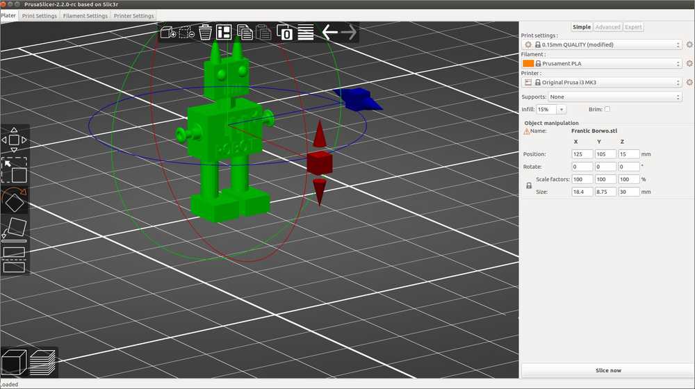
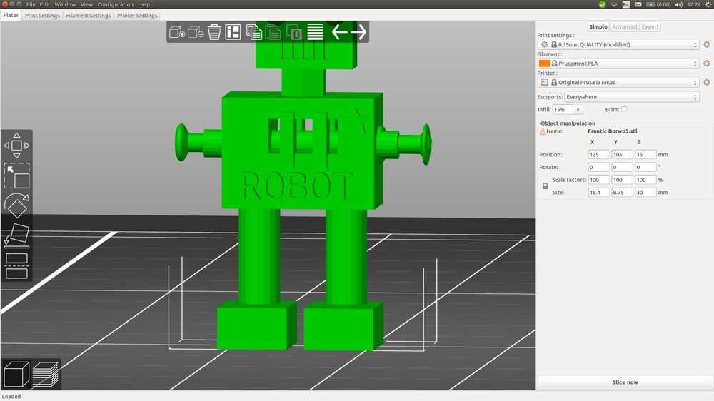
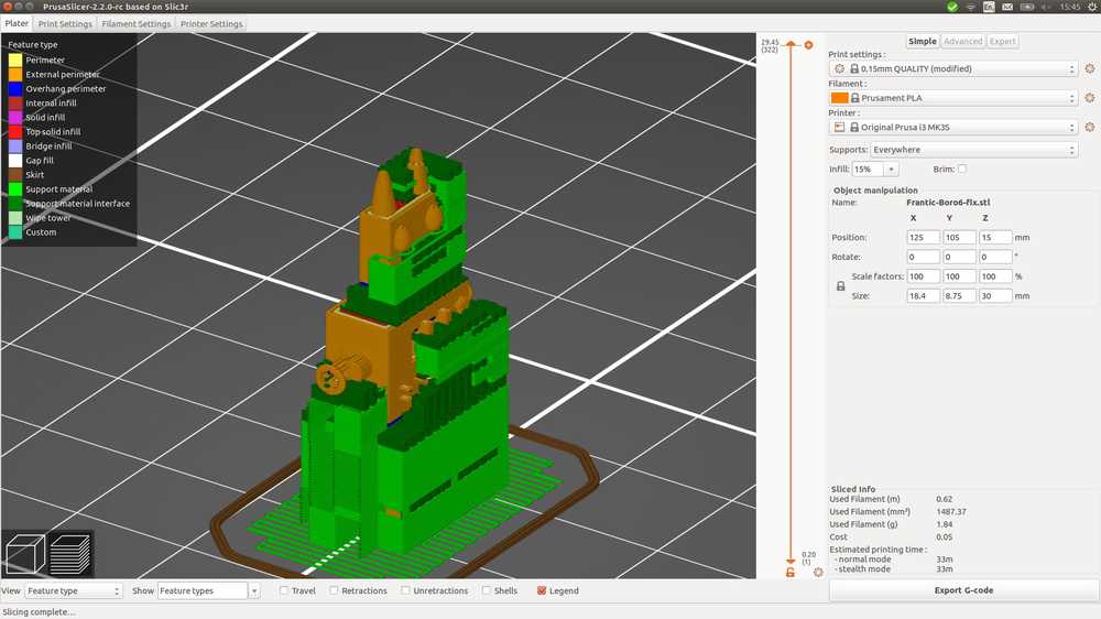
I select ‘supports everywhere’ from the drop down menu. But Slicer does not add supports. Which I find surprising. I would think the arms at 90 degrees angles would need support. Then I click ‘Preview’ at the bottom left corner (a pile of slices) and then there are supports everywhere. Much more than I expected.
 Support everywhere.
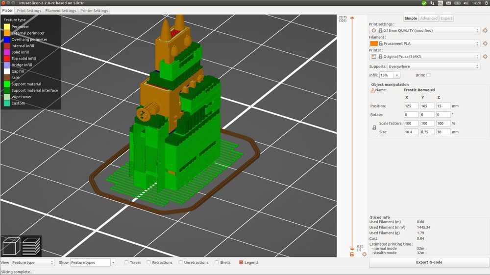
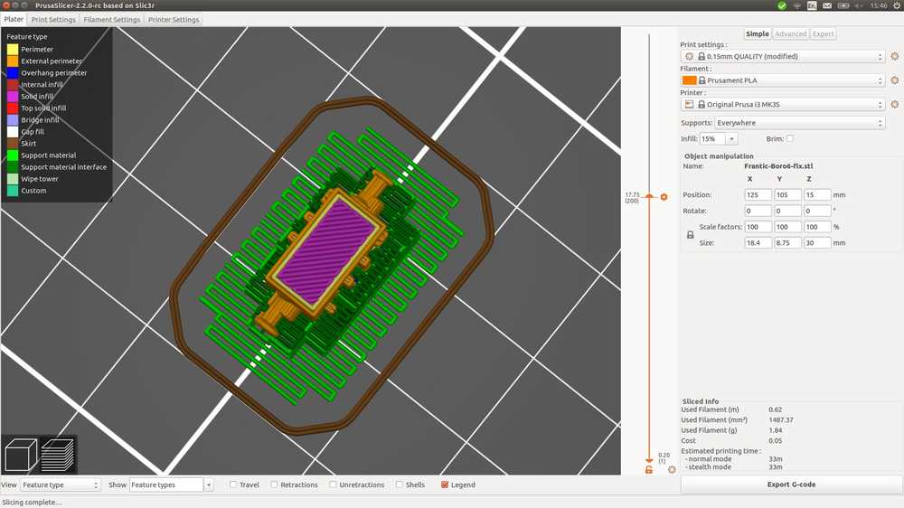
When choosing ‘support on build plate only’, you can have a good look at the cloro coded legend at the left. Overhangs in blue, perimters in yellow, top solid infill in red, etc. There are far more overhangs than I realized. I just thought of the arms but of course it is the body, the head, the grill, the mouth and the lettering too. I am starting to wonder if the hole in the chest is not too much overhang. In any case, I am going to use ‘support everywhere’.
 Support on build plate only.
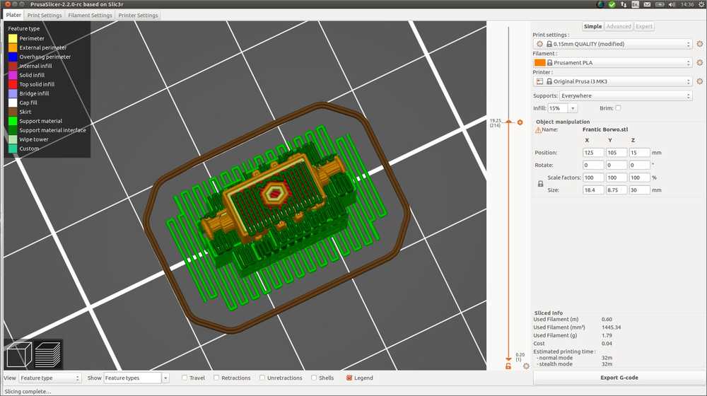
Support everywhere actually does fill up the chest. I wonder if it will be hard to get it out.
 Support everywhere.
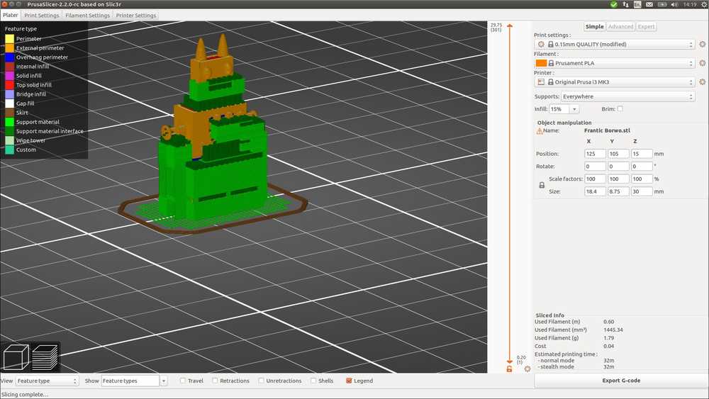
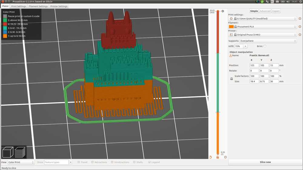
Using the slider on the left you can look at every slice. It’s very interesting. I made a screenrecording.
Slicing my robot in Prusa.
Most color codes are straight forward but I had to look up support material interface. From the Prusa3D website: ‘Interface layers form a more uniform surface between the object and the support material. These are preferably set to a much denser pattern than the non-interface layers so that you can both maximize the surface area of the support in contact with the model to prevent sagging while minimizing print time and material used with a bigger non-interface pattern spacing.’‘
 Slices.
I accidentally clicked the hexagonal at the left of the slicer. The color of the model changed I had to look up what it means. It is the colorprint feature. This helps you print in different colors. You can add to the G-code to tell the machine to stop printing so you can change filaments. Well I don’t want that. How do I undo these settings? At the bottom of the slicer is an round arrow that says: ‘discard all custom changes’. That works.
I then noticed there is an exclamation mark in front of the file name in panel on the right hand side. On the Prusa printer forum it states that this means there is something wrong with your model… Hmm. Hovering over it should tell you the mistakes. This does not work. Trying to export as G-Code works so the error does not prevent that.
In the menu I see File > Repair STL file. This does not repair the opened file but instead prompts you to open an STL file. It than saves it as an OBJ because ‘this is less prone to x errors (I forgot which and redoing the operation does not display the message anymore. In any case, opening the new OBJ file does not remove the exclamation mark.
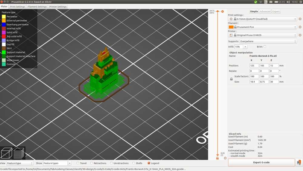
I press export code. The estimated printer time is 32 minutes. Much less than I expected after the 2.5 hours of the group assignment print.
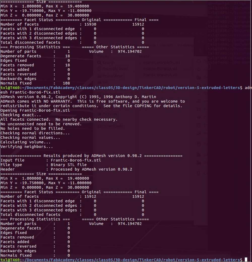
Conntinuing the hunt for the error message I land on stackexchange. They say that PrusaSlicer uses Admesh to detect and fix errors. If you want to see the errors for yourself they advise to use Admesh itself to check what the error is.
I find the Admesh webpage and install with sudo apt-get install admesh
Then I run admesh filename.stl, the command specified on the Admesh page. This is the output:
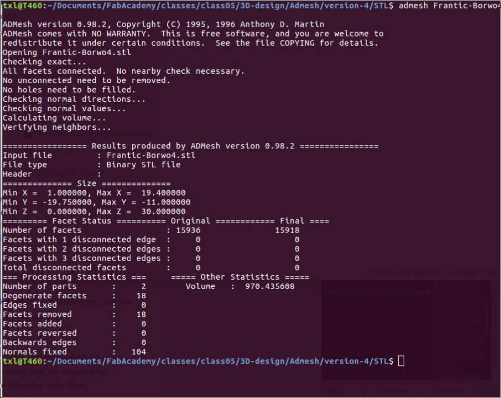
In the written text at the top there seem to be no major issues. (All facets connected etc.). But there are corrections noted at the bottom of the output. Such as degenerated facets which means the triangles aren’t making connections.
The Admesh page states that it will not make any alterations to the input file. If I understand correctly, the output above is just the outcomes of the test but the file has not been corrected. For corrections to take hold you need to specify with a write command: admesh --write-binary-stl=Frantic-Borwo4-2.stl Frantic-Borwo4.stl. The first file name is the new file to be created the second file name the original file.
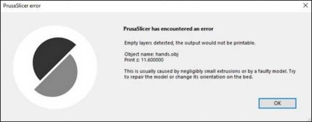
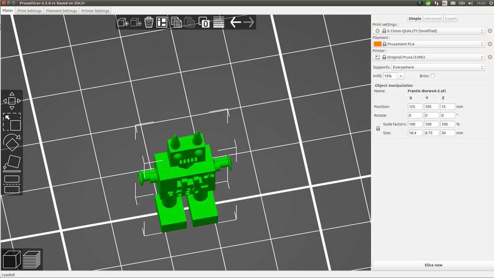 When I import it in PrusaSlicer there is no more exclamation mark. I don’t exactly follow what happened here. I had the impression PrusaSlicer makes use of Admesh to fix errors. So if Admesh fixed the errors, why didn’t Slicer do that as well? Maybe the exclamation mark only means that Slicer detected errors and has fixed them. Maybe a non-fixable error will result in PrusaSliver refusing to export to G-code. Because when I looked online searching about the error people reported errors like these:
So now I am not sure which is the best file to try for printing. I’ll start with the one that Admesh fixed and does not give an error message anymore in Slicer. But that will have to wait till tomorrow because today is Sunday and the lab is closed.
To prepare the files tomorrow:
- Check what kind of filament we have and set the correct settings in Slicer.
- Make sure printer settings are on the MK3.
- In Print settings choose 0.15 mm Quality.
- Under platter: Add supports everywhere.
- Slice and check in the preview.
- Generate G-code from the Admesh file. Located under class05 > 3D-design > G-code > Admesh > STL > Frantic-Borwo4-2-fix.stl.
3D printing the design
We have different types of filament in the lab but I choose to use the filament of Prusa because I am going to use the Prusa MK3 printer. Also by now I have the impression that Josef Prusa, the maker of the Prusa printers knows what he is doing.
I am usnig the PLA Galaxy Silver. The specifications on the swindle state that Nozzle temperature should be 210 degrees with a 10 degree margin. The heatbed should be at 50 degrees with a 10 degree margin. The diameter is not specified on the role so I look up the ID number on the internet: ID 20446fc5. I find it here. It’s 1.75 mm filament.
I enter these filament specs in PrusaSlicer. I choose MK3 as a printer. I import my design, the one that was fixed by Admesh. I choose ‘build supports everywhere’. I have it sliced and check it with the slider. I exported as G-code and load it unto a SD-card. The first SD-card isn’t recognized by my computer, a second one is.
Prusa i3 MK3S
 Switch on.
And click the main (round) button to enter the menu.
Switch on.
And click the main (round) button to enter the menu.
 Preheat.
 Choose PLA.
 Cut filament into a pointy tip and manually add it to the tube.
 Click ‘load filament’ in the menu.
 The printer should extrude the filament. First it may be another color from a previously used filament.
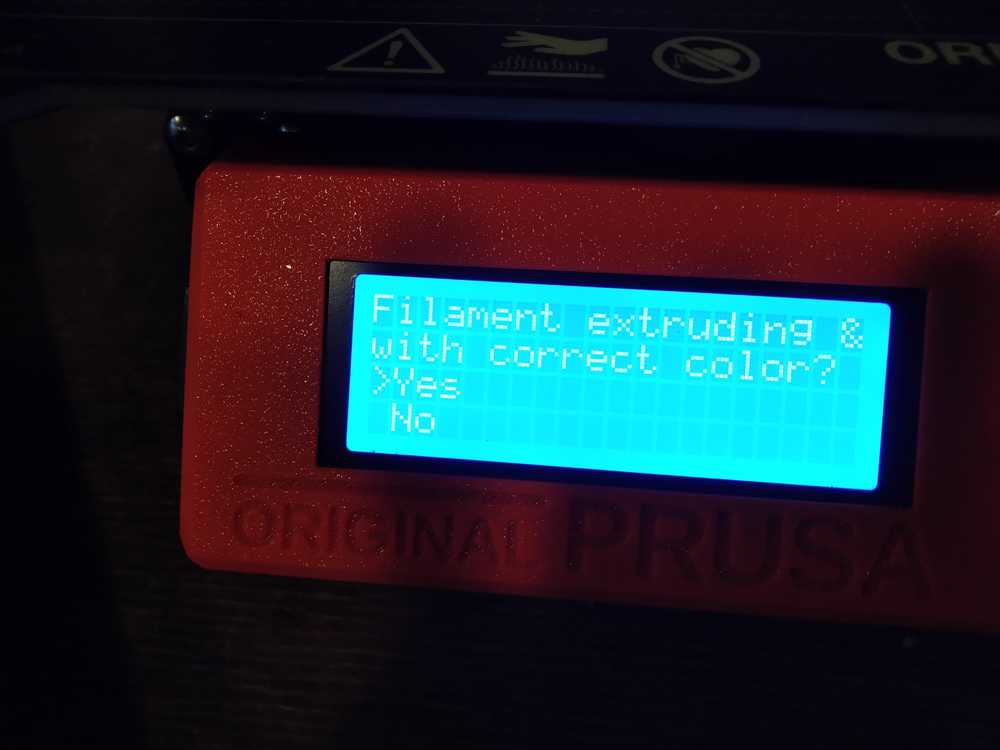 Click yes it the filament is the correct color.
Troubleshooting if the filament is not extruding.
If the proper color or no filament at all is coming out, press ‘no’ when the printer asks. The printer should now automatically try again. Do this procedure a maximum of two times. If the filament still isn’t correct, listen to the stepper motor in the head, does it sound like it is stuck?
Switch off the printer. Remove the tube from the head of the printer. Manually press the filament deeper into the head. This can not be done with the printer switched on because the stepper motor will resist the filament. Reinsert the tube and switch on the printer.
If this still does not work, load ABL filament. Heat the nozzle till around 167 degrees. The ABL will melt a little and surplus filament will stick to it. Then pull it out.
 Remove filament tube from the nozzle.
You can now start anew:
Preheat again.
Load filament.
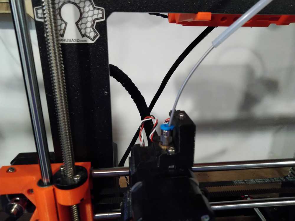
 Extrusion looks good.
Select print from SD.
Make sure the selector arrow pints to the correct file.
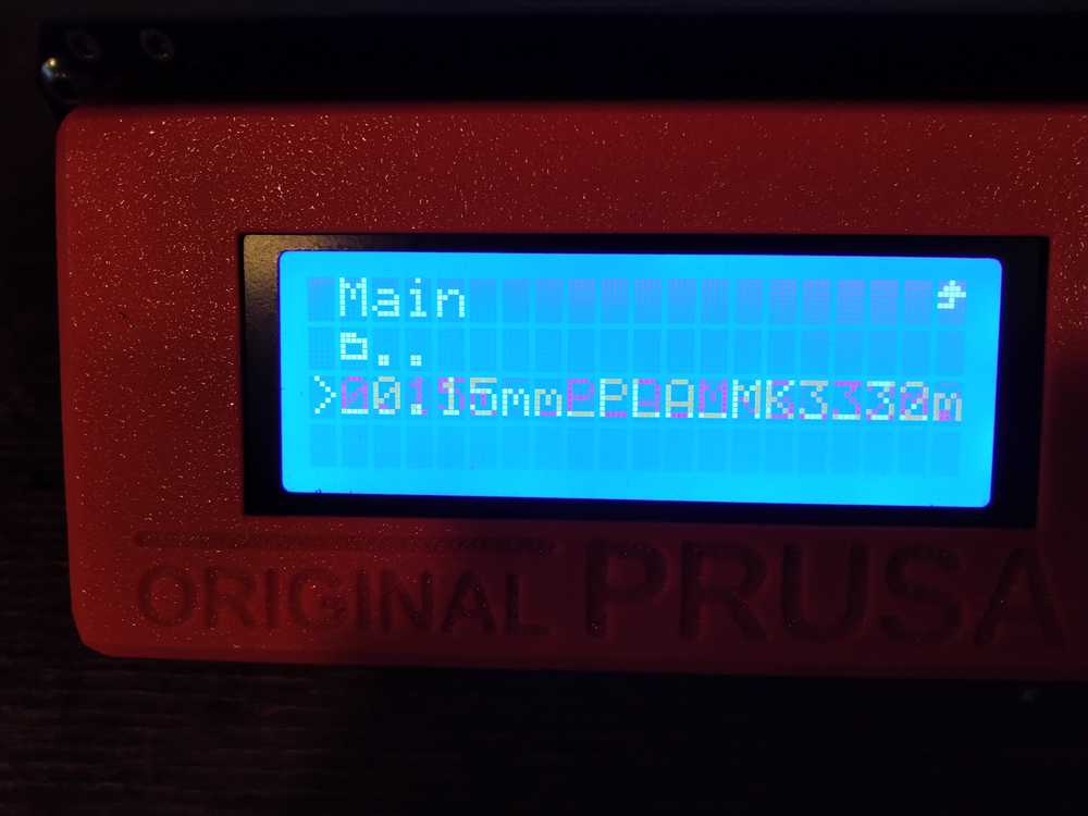
Then I received a error message: G-code sliced for different printer.
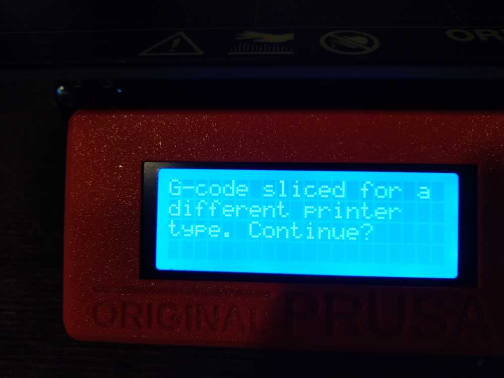
I asked people in the lab and they told me we have an MK3S printer. Not an MK3. I am a big proponent of printing make and model clearly on devices.
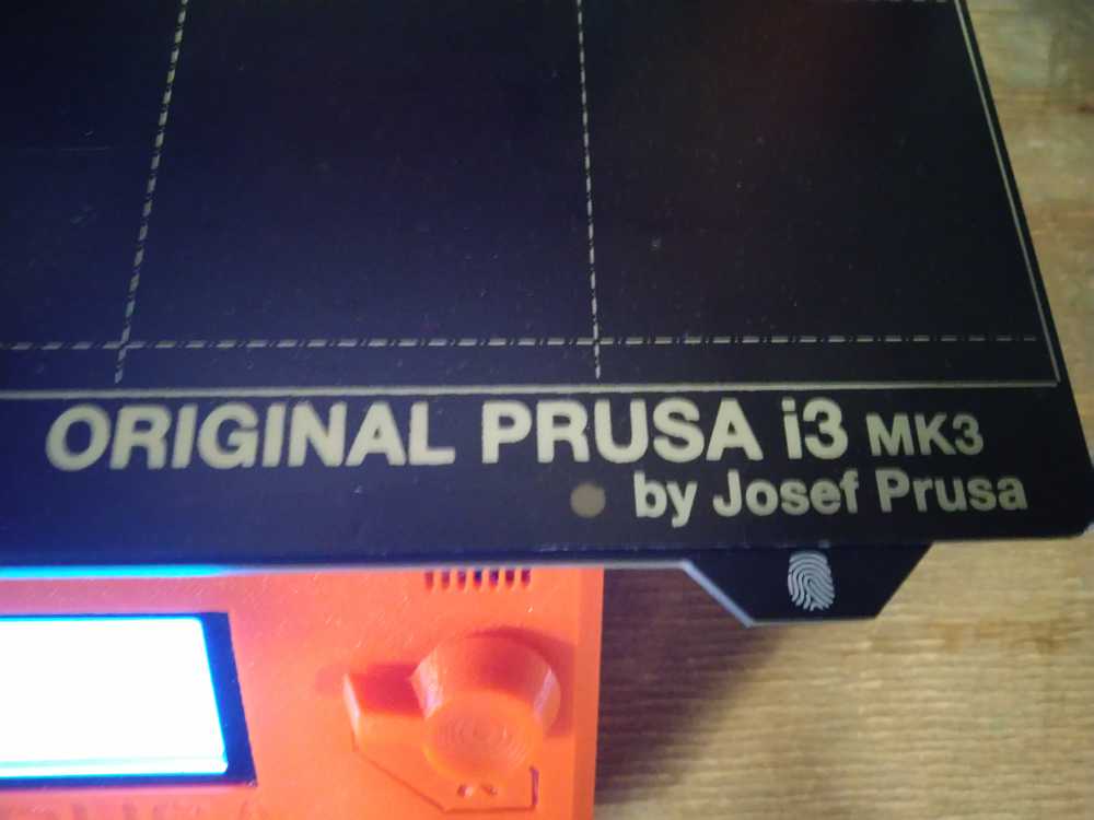 This should read MK3S.
So I go back to PrusaSlicer, select the right printer and export to G-code.
Prusa then warned it wanted its firmware updates. The folks in the lab told me you can ignore that. Press the round button to continue.
I run the steps again:
preheat PLA.
Load filament.
print from SD.
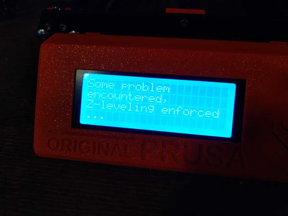 The printer starts and then responds: ‘Some problem encountered: z-leveling enforced’.
But it handles that itself. The bed is moved over the Z-axis. The message returns and the printer automatically responds again. Then the message ‘callibrating’ appears.
And starts printing!
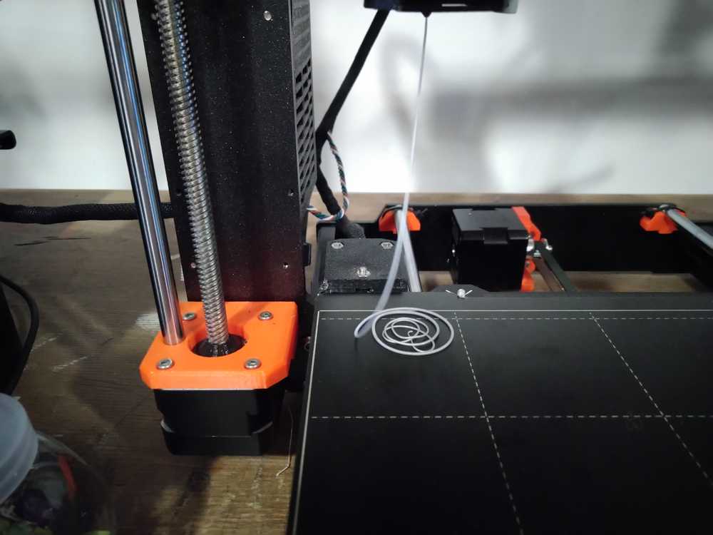
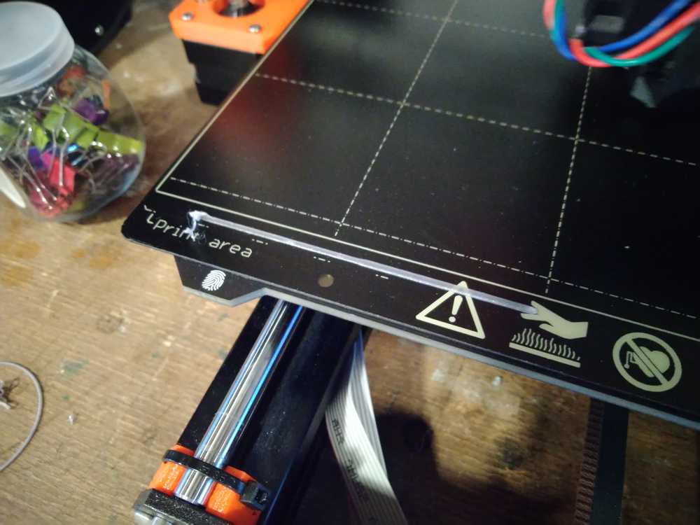 The test stripe.
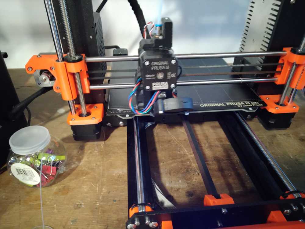
 Printing in action.
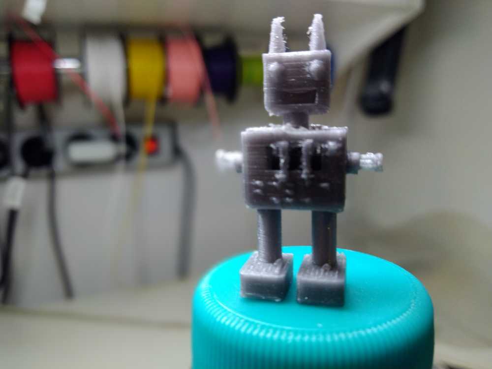
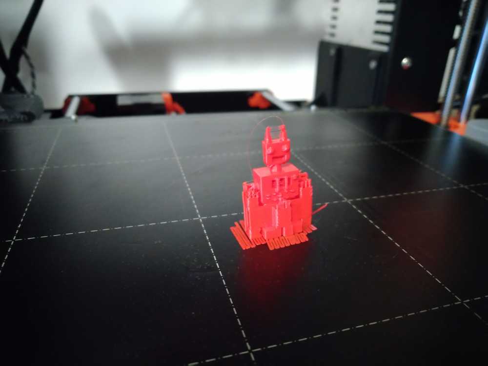
 Done! As soon as the robot was finished Rinke named it Robin.
Clean up the printer after you are done.
 Begin with unload filament.
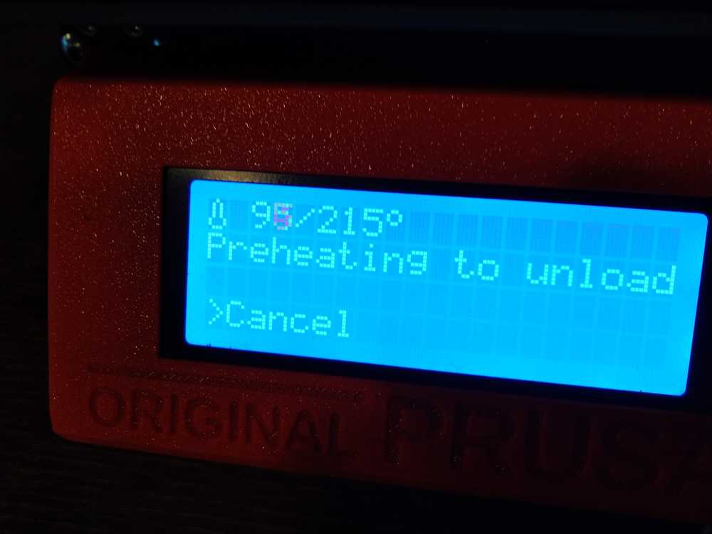 The printer starts heating up for that action.
It beeps when it is ready. Press the round button to unload filament. Another beep informs you to remove the filament manually.
Switch off the machine.
Clean the bed.
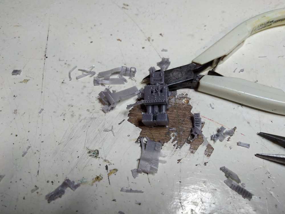
Removing supports
I first watched a short Eezitec tutorial on removing supports. For tools you need: tweezers, needle nose tweezers and small snips. Take the tweezers, go to top end of support structure and lightly rock them back and forth to pull them off.
Sometimes a little know of filament stays behind. You can choose to use the tweezer or use nail vile.
Raft: you can choose to leave it on for better support. Hold model with one hand and rock raft back and forth. Sometimes you may need to use the snips.
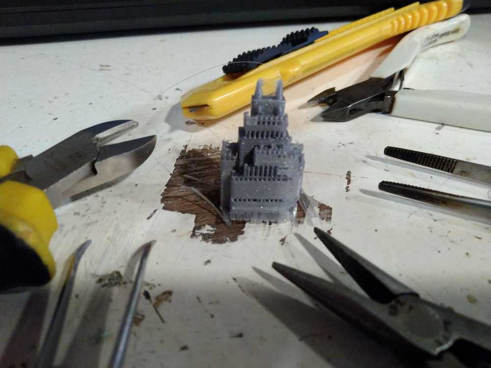 Removing supports.
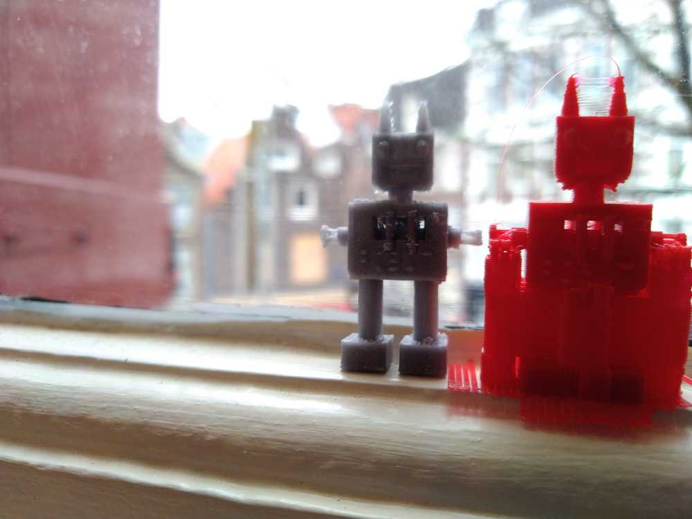
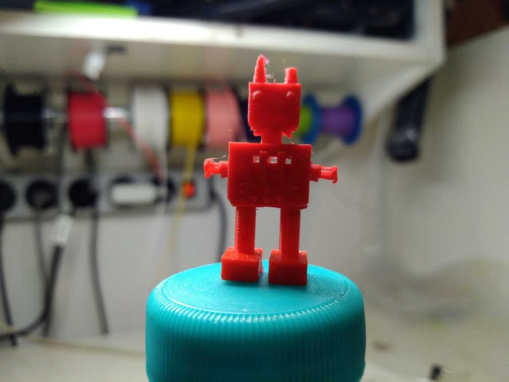
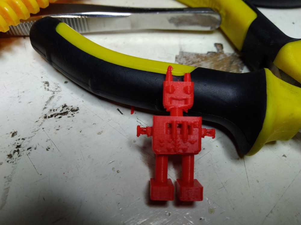
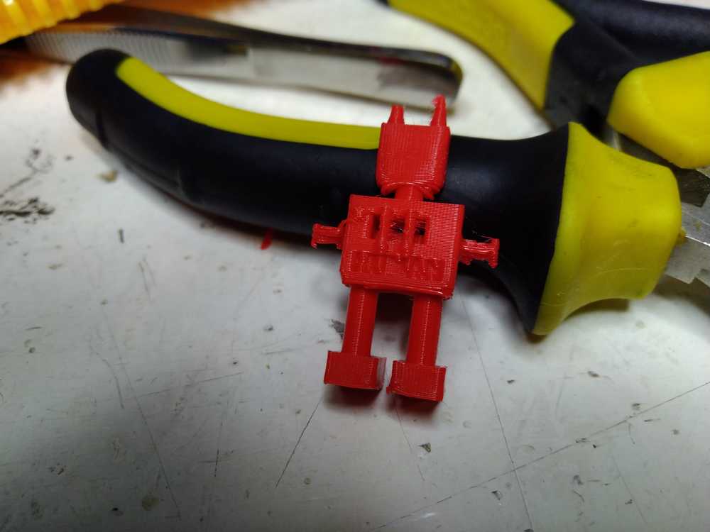
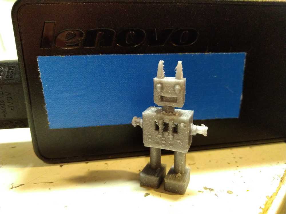 Meet Robin the robot!
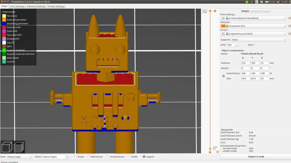
There are a few things that aren’t not perfect about the printed result compared to the design. In the design made the mouth by adding several slots, but in the final model it’s a solid open slot. This is the result from a mistake in the design I think.
The embossed lettering stating ‘ROBOT’ has hardly taken on. The indented lettering on the back stating ‘HUMAN’ is slightly more readable but not very good either. I thought the robot text may have been accidently removed when I was taking of the supports.
But the least good thing is the chest. Supports were added inside the chest to support the overhang. But with the grid in front of the opening, the filament can not be removed.
 The open chest in TinkerCad.
 The open chest in PrusaSlicer.
 The exterior chest with the supports in Slicer.
 The interior sliced view of the chest in Slicer.
 The open chest is clogged with filament.
I decided to do another run. This time I would change the setting in PrusaSlicer to ‘support on build plate only’ instead of ‘Everywhere’. I also went back to TinkerCad and made the embossed lettering protude 1 mm instead of 0.5 mm. I looked at the grill on the mouth to see why it had not translated to the .STL file but I could not really see any reason.
I also looked into the exclamation mark I encountered yesterday. I asked Jules from our lab if he knew what it meant. He hovered over the mark, thinking that it might give a message, just as I found online yesterday. Maybe it is a feature that does not work in Linux or something. He explained it means a mesh isn’t right. He looked closely at the slices and noticed that the second half of the arms is hollow, whereas in the design they are solid. He thought the mark might be referring to that.
 The arms are hollow, while I intend them to be solid.
I must admit I had not seen the hollow arms, but looking at Robin the robot I saw that the arms were indeed printed hollow.
I ran the design through Admesh again. The exclamation mark was gone but the arms were still hollow. Is we will see later, the mouth also wasn’t corrected. So that does not seem to be a mistake in the mesh but rather in the design. What I learned from Jules is that you can also closely look at the slices to see if you see something is of.
I
So I ran the design through Admesh again but forgot to add .STL to the command:
admesh --write-binary-stl=Frantic-Boro6-fix Frantic-Borwo6.stl I noticed when PrsaSlicer would not detect the file in the directory. So I ran it again: admesh --write-binary-stl=Frantic-Boro6-fix.stl Frantic-Borwo6.stl
Here is the output of Admesh: above is the Admesh checking for and reporting on errors, below is the output after the errors are fixed.
After fixing the file I run it in PrusaSlicer and select ‘support on build plate only’. The grid on the mouth is still not there and the arms are still not solid. For now I am leaving it as is. The most important test is if the different support setting is going to leave the chest open and does not sack for lack of supports doing printing.
I choose a different color filament. There is not much left on the spindle. Michelle points out that Slicer also tells you how much filament you need. My model requires 0.52 m. There is enough filament left of the red color to print another robot.
 Rinke also immediately named the second robot: Chappie. After the South-African movie robot Chappie.
The main aim has succeeded: the chest is no longer clogged. And it isn’t sagging for lack of support.
 You can see the difference in the chest against the backlight.
 Another chest shot.
The front and back lettering haven’t much improved.
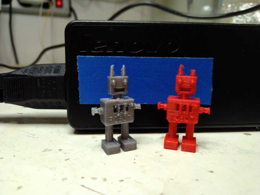 Robin and Chappie.
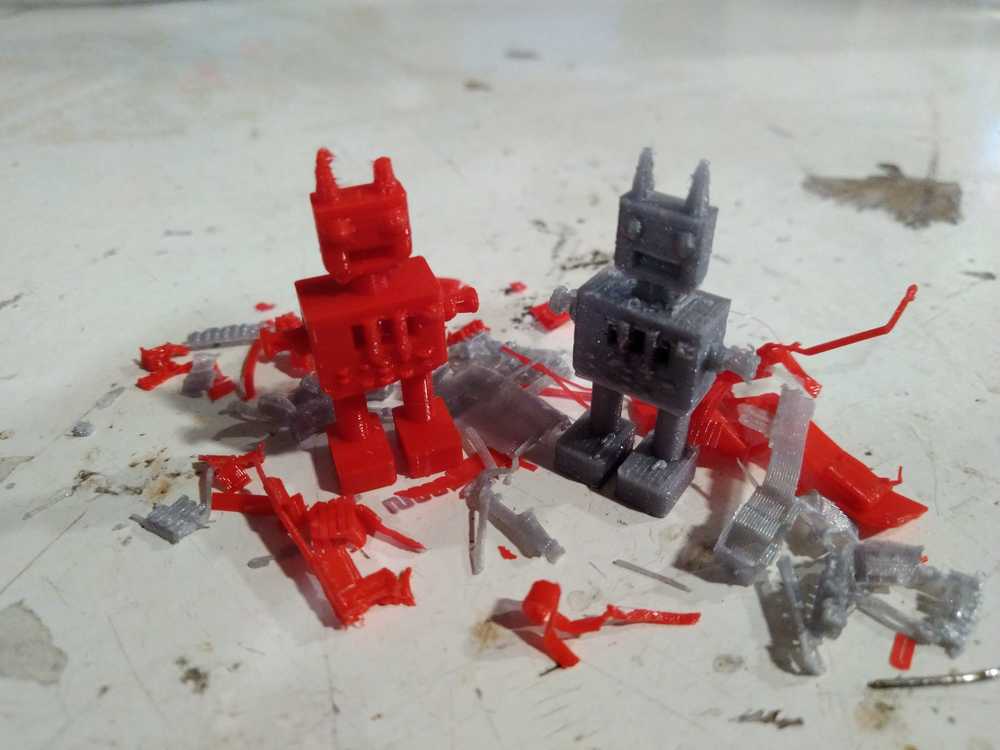 Chappie has lost part of his antenna during de-supporting.
3D scanning
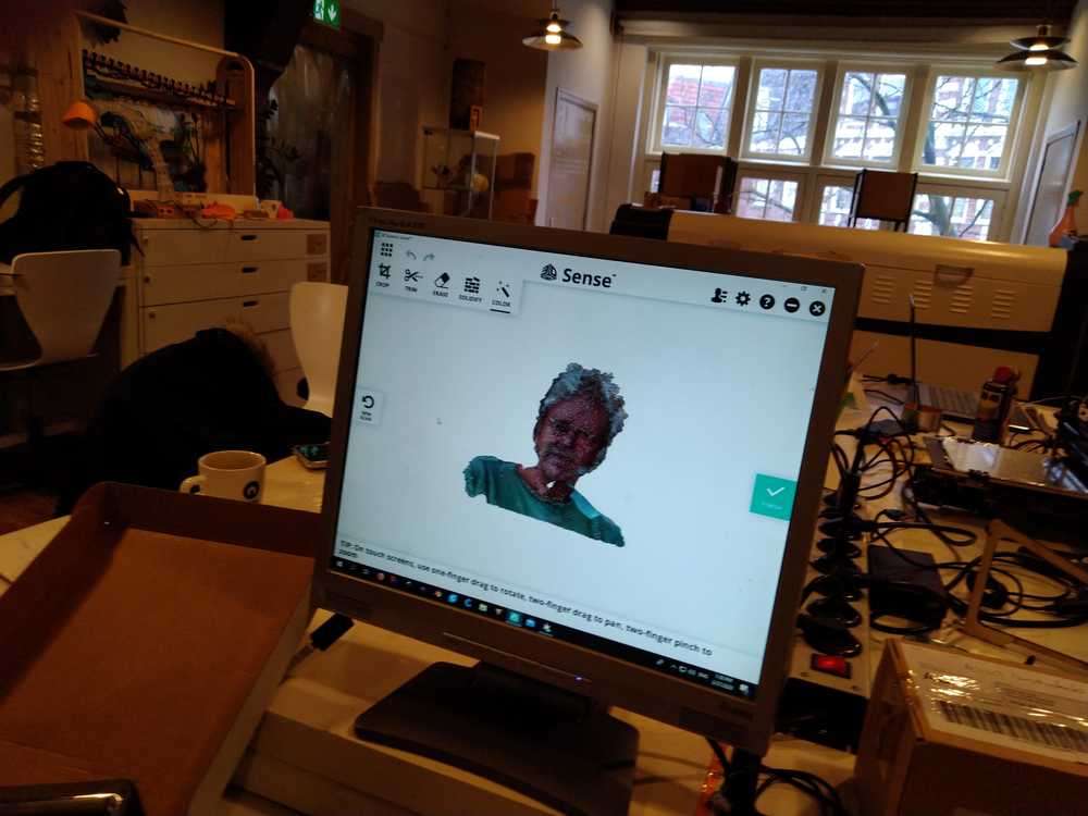
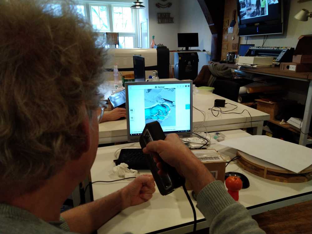
Rinke and I then went on to do 3D scanning. We had a hard time scanning a tangerine. We tried it in several ways. First by slowly moving the scanner by hand. But the scanner would loose the picture almost immediately. We tried several distances and we tried several angles and several speeds of moving our hand. The scanner would start out having a picture but loose it really fast.
We then tried using a platform that rotates very slowly. The platform had a bed that has lights beneath it that shine through the bed. This did not work at all because the scanner kept focussing on the lights.
Next we tried using the slowly rotating bed with a piece of white paper on it to mute the lights below the bed. It also gave it a solid white back ground. None of this worked, the scanner kept loosing the image immediately. We tried rotating the platform at different speeds. From fairly fast to almost inperceptably slow.
In the end we did not manage to scan the tangerine. The problem may be that a tangerine does not have a lot of markers for the scanner to pick up on. It is a round object with very few differences on the surface.
Next to the tangerine we also tried other objects: We tried a white cup. This does not work because it has too few markers.
We tried a face, that worked well during the group assignment. But we could not reproduce that success.
In the end we recalled Henk telling the story that he too had a problem with the scanner in 2018. In anger at the scanner he scanned a raised middle finger. And then the scanner worked. So we too tried to scan a hand. Only we folded it into a fist.
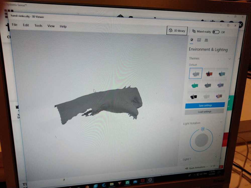
This worked. Rinke held up his hand and started slowly scanning, the image caught on and did not fail. I took over from Rinke to scan the other side of his hand so he could remain sitting still.
This time the scanning worked and we could export the model. The scan resulted in a .OBJ file of 7,6 MB so I am not going to add that to my source files. It is now uploaded to https://sketchfab.com/.
Git
The Git pipeline failed when I was uploading my picture. Fix: Go to Gitlab > CI / CD > pipelines. Click the ‘redo’ arrow at the right of the pipeline. This will recommit the failed pipeline.
What went wrong
There were multiple things that went wrong but nothing drastically or dishearteningly. There were mistakes in the STL files but Admesh fixed them for me.
Not everything went well on first try on the 3D printer but most things had easy fixes. As easy as just do it again. The 3D printer is like HTML: it just soldiers on. Very different from the milling machine for which you need to get everything exactly right. I like both, by the way, the ease of the 3D printer and the regimented exactness of the milling machine.
The other thing that went wrong were the supports. On the first run I added supports everywhere. The result was that there were supports inside the robot’s chest which could not be removed because it has a grid before it. A second run with the setting ‘supports from platform only’ solved this mistake.
3D scanning turned out to be less forgiving then 3D printing. The facial scans during the group assignment went well but on our own Rinke and I hardly got a decent scan out of it.
What I liked.
I wasn’t all that interested in 3D printing in advance. But doing the design was actually nice to do. Having your design come out as a physical object is super nice. It was nice printing in two different settings and seeing real differences in the result. I think you can actually get really into 3D printing. Seeing what works and what not. I liked the Prusa printers and software.
It is interesting to see there is a whole world of 3D print afficionado’s out there who build printers, software, files and share it all. I can really see how you could get hooked on this is there is a near infinite amount of things to learn about it.
I suppose 3D printers have come a long way in just a few years. I remember a couple of years back people playing around with 3D printers where calibrating them 88% of the time. Their hard work and persistance has resulted in these easy to use printers. The many benefitting from the few. Thanks 3D nerds!
Global lecture
Design rules: test how thin a wall can be before it collapses. The opposite is how thin a gap can be before it fuses. Overhang can not go far before it collapses. Bridges get much farther. You can build large overhangs by using supports. But try to avoid them. Don’t design objects with sharp points, there will be not enough fillament in the sharp point.
Don’t design in a void, design around the limitation of the printer.
Group assignment: Characterize the design rules of your printer and design around it.
Software: You need 3D design software and slicing software to do the slicing.
https://sketchfab.com/3d-models/hand-3d-scan-d1b351ec2a254905aadc42f14f16f84f