9. Input devices
Amsterdam. March 25, 2020
To do
| Description | status |
|---|---|
| Group assignment: | done |
| Document my part of the group assignment | done |
| Pick a sensor | done |
| Design a board involving the sensor | done |
| Make a board from the design | done |
| Program the board | done |
| Read out the sensor data from the board |
Source files
| Description | link |
|---|---|
| KiCad project files for the step response sensor board | Downloadable zip. |
| Traces and cutout for the board can be found below under the PCBnew paragraph | https://fabacademy.org/2020/labs/waag/students/tessel-renzenbrink/assignments/week09/#pcbnew |
| Code and makefile for the step response sensor from Akash | Downloadable zip. |
| Code for operating lightsensor and serial read out | Downloadable zip. |
urls
| Description | link |
|---|---|
| Index of this week’s topic | http://academy.cba.mit.edu/classes/input_devices/index.html |
| Global lecture video | https://vimeo.com/400735149 |
| Global review video | https://vimeo.com/403070894 |
| Group assignment documentation | https://fabacademy.org/2020/labs/waag/groupAssignments/week9.html |
| FabLab inventory list | https://docs.google.com/spreadsheets/d/1U-jcBWOJEjBT5A0N84IUubtcHKMEMtndQPLCkZCkVsU/edit#gid=0 |
| Arduino step response piano project | https://www.instructables.com/id/Capacitive-Touch-Arduino-Keyboard-Piano/ |
Group assignment
A full description of the group assignment can be found on our communual page.
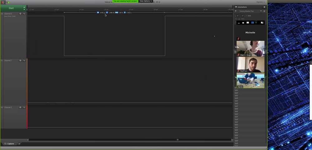
Screenshot of the online class setup. We’re using videoconferencing and Henk is sharing his screen showing the logic analyzer.
For the group assignment we had to probe an input device’s analog levels and digital signals. We have all received a take-home kit met dev boards and components for the duration of the social distancing period. We all have a NodeMCU 1.0 board and a Ultrasonic sensor. We worked together in a video conferencing room, each of us setting up the board and sensor at home. Harm is very familiar with doing these kind of things and he helped me setting up the board and sensor. Then under Tools > Board select the ‘Generic ESP8266 module’
Setting up the NodeMCU for Arduino
Each of us then connected the board to our computer and started up the Arduino IDE. We had to set up Arduino to work with the NodeMCU by adding the board. Under the files > preferences tab, add the link to the additional boards manager window. Add the following link: https://arduino.esp8266.com/stable/package_esp8266com_index.json. (If there already is a library in the window just add a comma and add the new library behind it.) Then go to board manger and Add board, Search for ESP and install the board.
Setting up the Ultrasonic Ranger V2.0
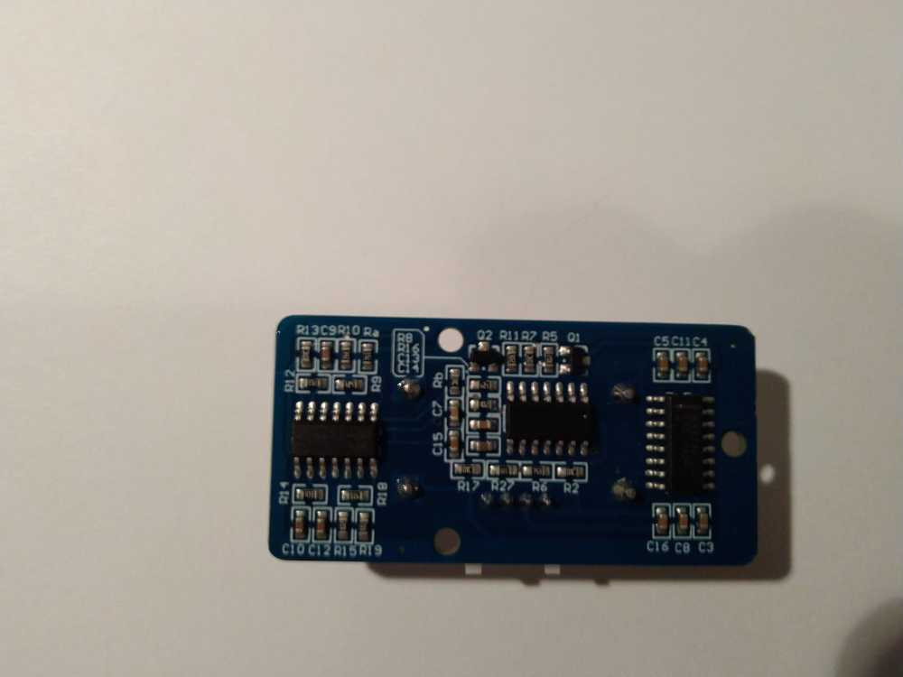
The others had a HC-SR05 sensor and I had a Grove Ultrasonic Ranger v2.0. This board has no further specifications on it. Here are pictures of the front and back: there are no specifications shown.
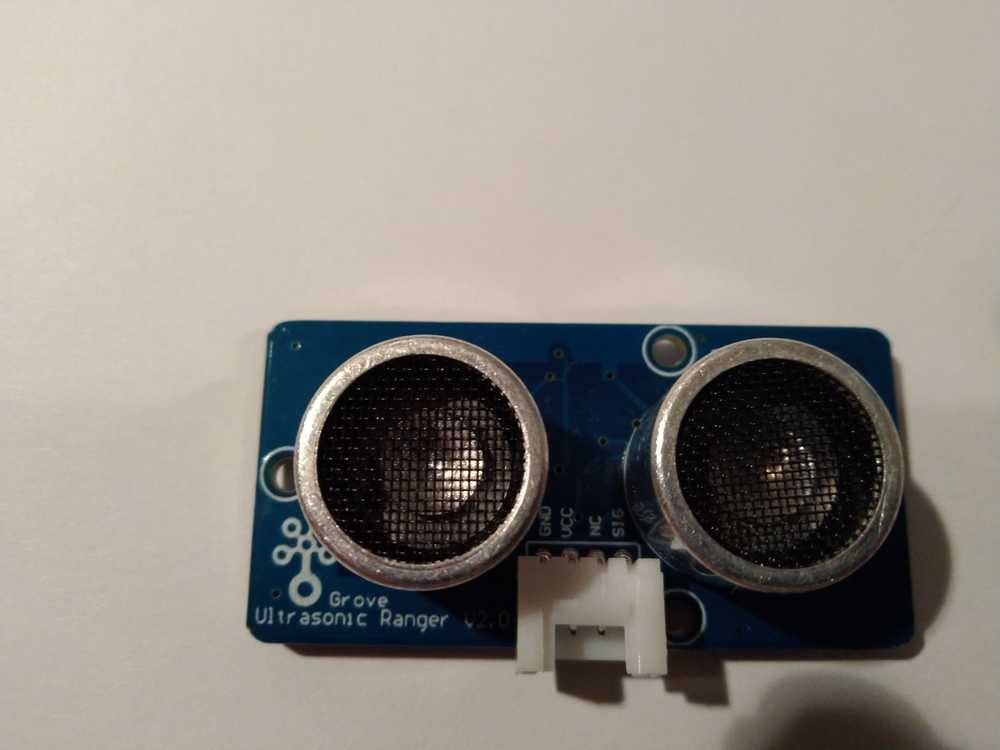
The difference is that the HC-SR05has four pins while mine has only three. Next to VCC and GND there is a sig and nc pin. Nc stands for not connected, so this sensor has only three pins. I connected the VCC pin of the sensor to Vin of the MCU. The GND to GND and the SIG pin of the sensor to the D1 pin of the board. This also meant that a different code was needed to set it up. The code is not really good code, there is extra stuff that is not needed. But it does work.
const int pingPin = D1;
int M1 = 12;
int M2 = 13;
int C;
void setup() {
 // initialize serial communication:
 Serial.begin(9600);
 pinMode(M1, HIGH); //to control motor
 pinMode(M2, HIGH);
}
void loop()
{
 // establish variables for duration of the ping,
 // and the distance result in inches and centimeters:
 long duration, inches, cm;
 // The PING))) is triggered by a HIGH pulse of 2 or more microseconds.
 // Give a short LOW pulse beforehand to ensure a clean HIGH pulse:

 pinMode(pingPin, OUTPUT);
 digitalWrite(pingPin, LOW);
 delayMicroseconds(2);
 digitalWrite(pingPin, HIGH);
 delayMicroseconds(5);
 digitalWrite(pingPin, LOW);
 // The same pin is used to read the signal from the PING))): a HIGH
 // pulse whose duration is the time (in microseconds) from the sending
 // of the ping to the reception of its echo off of an object.
 pinMode(pingPin, INPUT);
 duration = pulseIn(pingPin, HIGH);
 C = digitalRead(duration);
 if (C > 2*cm)
 {
 digitalWrite(M1, HIGH);
 }
 else
 { digitalWrite(M1, LOW);}
 // convert the time into a distance
 inches = microsecondsToInches(duration);
 cm = microsecondsToCentimeters(duration);

 Serial.print(inches); // to serially print the data
 Serial.print("in, ");
 Serial.print(cm);
 Serial.print("cm");
 Serial.println();
Serial.println(duration);
delay(100);
}
long microsecondsToInches(long microseconds)
{
 return microseconds / 74 / 2;
}
long microsecondsToCentimeters(long microseconds)
{
 return microseconds / 29 / 2;
}
The code worked and we opened the serial monitor in the Arduino IDE. Here we could read the output of the sensor.
Here is a video of the output in the serial monitor of the Arduino IDE. Output alternates between distance and duration.
output ultrasonic sensor from Tessel Renzenbrink on Vimeo.
2. Register the sensor data via an analog device
According to the datasheet The trigger pin is triggered when it is set to HIGH for at least 10 microseconds. The module then sends 8 40KhZ pulses. If the pulses encounter an object they are bounced back. The range in which the module can register the returning pulses is 3 meters. When a returning pulse (echo) is received you can calculate the distance to the object. The formula is
time x velocity of sound (340m/s) / 2.
Time is the time it takes for the pulse to be send, bounced back an received. You divide by two because the pulse traverses the distance twice.
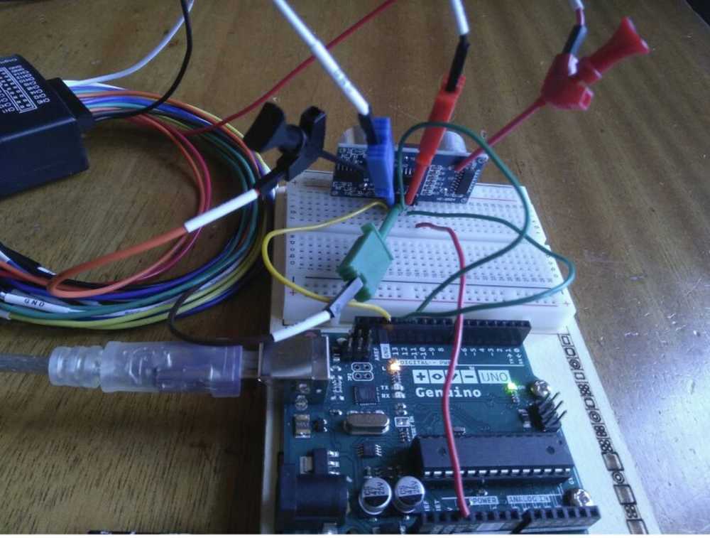
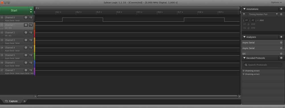
Working from home because of the pandemic, we asked Henk to connect his logical analyser to the device. The two pictures below show Henk measuring 4 channels. The first picture shows the logical analyzer connected to four pins. The second picture is the output of the logical analyzer.
Channel 0 is connected to the trigger pin.
Channel 1 is connected to the echo pin.
Channel 2 is connected to the ultrasonic speaker.
Channel 3 receives the echo’s.
The way the sensor works is as follows: the Arduino sends a signal to the trigger pin. If it is put HIGH for more than 10 microseconds it sends out 8 pulses out of the speaker. At this moment the ECHO pin is set HIGH. If the module receives a signal back, the ECHO pin is set LOW. So the time the pulse traveled is equal to the time the ECHO pin was in HIGH state.
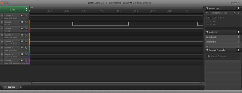
The echo signal on channel 3 goes from small to bigger to small again. This is because it works like an echo when you scream in the mountains. You hear the echo back and then the echo of the echo of the echo.
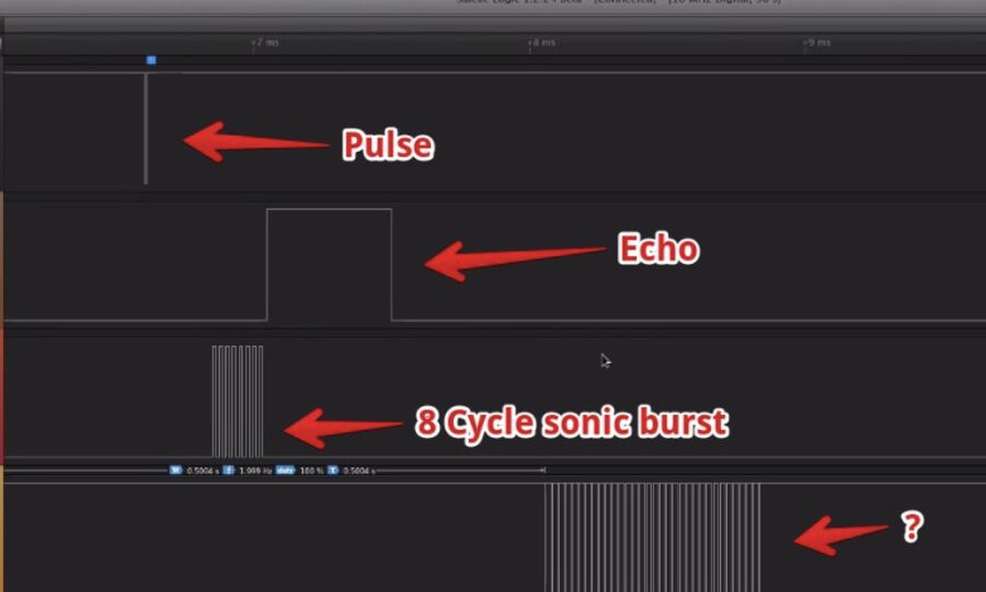
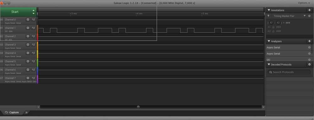
Henk measured two different distances with the sensor. You can see the outcome in the two pictures below. The shorter distance measured 0.1452 ms. Using this measurement you can calculate the distance:
In the example Arduino code for the ultrasonic sensor (see at the bottom of the page for entire code) we see the following:
 // The speed of sound is 340 m/s or 29 microseconds per centimeter.
  // The ping travels out and back, so to find the distance of the object we
  // take half of the distance travelled.
0.1452 milliseconds = 145.2 microseconds. Sound travels at 29 microseconds per centimeter. 145.2 us / 29 = 5.007 This must be divided by 2, because the sound travels to the measured object and back again. Therefore the distance that was measured is 2.503 cm.
The longer distance that was measured is: 0.4395 ms = 439.5 us 439.5 / 29 = 15.1552 15.1552 / 2 = 7.5775 cm The longer distance measured was: 7.5775 cm
What I learned
It was good to do this group assignment because working together with my class mates really accelareted setting up the board and the sensor. They know how to do it and showed me how. Last week they already explained about the serial output monitor in the Arduino IDE. And this week I saw how it was used. So through the group assignment I got a good idea of what we have to do for this week.
Another thing I liked is matching the code to the output signals on the logical analyzer. I like how concrete everything is. If you use a sensor that uses sound, you need to apply the speed of sound in your code. It was interesting to match what is happening in the sensor to the output of the digital analyzer. I wasn’t able to match entirely what I thought the code was doing to the output of the analyzer. In the code most of the action happens on one pin. But in the analyzer we measured for channels. So I could not match every signal to an event in the code. But I do have a good idea on how you can use the analyzer to read out your sensor. If I have time this week I will try to read the sensor for the individual assignment with a logical analyzer.
Individual assignment
Measure something: add a sensor to a microcontroller board that you have designed and read it.
Pick a sensor: step response
I will pick the step response for the sensor to fiddle with. The primary sensor for my final project will be an antenna. But I do not know if that counts as a sensor and that will probably be addressed in the networking week. For the spiral development of my final project I would like to add a way to input data. A crude keyboard might be the way. The step response sensor might be a way to generate input through touch. I started researching how to do this by going to Micky’s page.
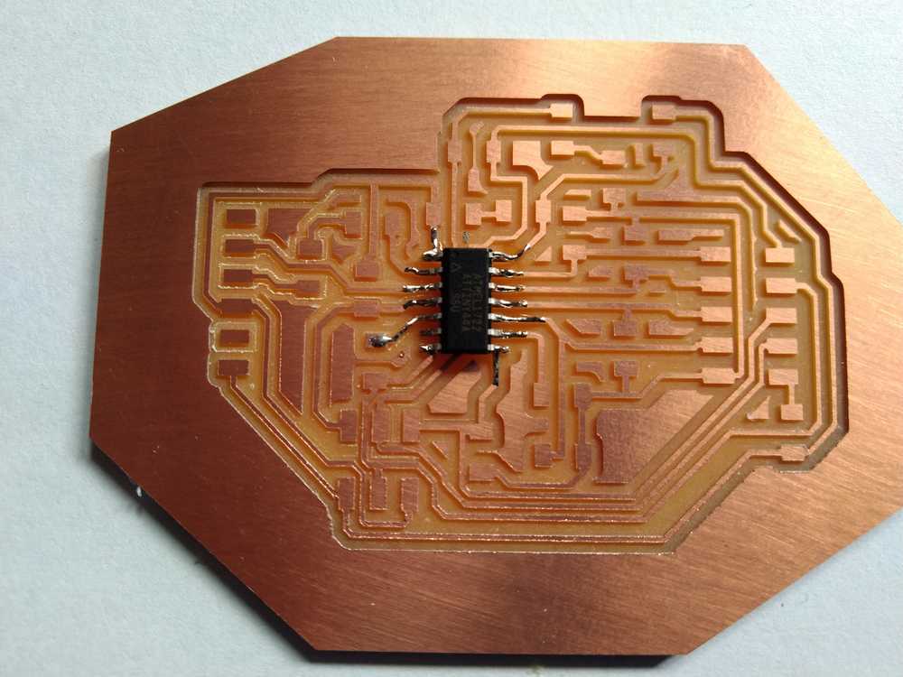
She referred to other pages of FabAcademy students that she had looked at: Matt Blackshaw, Matthew Keeter, Frank Vloet, Hyebin Goo and Akash Badshah. I really liked how they all had come up with really different designs. I liked Fank Vloet’s design with the open wires and vinyl cutted pads. But most I liked Akash’s board as he has used the copper of the board as the touch pads. I will take my cue from him.
Design the board
Akash and Frank both have Eagle files of their board and I don’t have that program. But you can view Eagle files in the browser at https://www.altium.com/viewer. This is really helpfull. It has a second tab that lists the Bill of Materials. Later I learn from Henk you can also import Eagle files into KiCad.
Components
The components I’ll need
| Component | Specifications | Orientation | Quantity | Designator |
|---|---|---|---|---|
| ATtiny44 | ATTINY44A-SSU-ND | Yes | 1 | IC1 |
| ISP 6 header 2x3 | KiCad library: AVRISPSMD. Inventory list: 609-5161-1-ND. Digikey: CONN HEADER SMD 6POS 2.54MM | No | 1 | JP1 |
| FTDI header 6 pin | KiCad library: FTDI-SMD-HEADER | yes (consider how the cable should be plugged in) | 1 | |
| Capacitor 1uF unpolarized | CAP CERAMIC .1UF 250V X7R 1206- | no | 1 | C1 |
| Resistor 10k | Library: RESUS-1206. Inventory list: RES 10.0K OHM 1-4W 1% 1206 SMD | No | 1 | |
| Resistor 1M ohm | FabLab inventory list: 311-1.00MFRCT-ND. Digikey: RES SMD 1M OHM 1% 1/4W 1206 | No | 8 | |
| Resistor 0 ohm | FabLab inventory list: 311-0.0ERCT-ND. Digikey: RES SMD 0 OHM JUMPER 1/4W 1206 | No | 7 | |
| 10header 2x5 | KiCad library: PINHD-2X5-SMD. Inventory list: 609-5163-1-ND. Digikey: CONN HEADER SMD 10POS 2.54MM | no | 1 | 10HEADER |
| Ribbon cable | yes (connect pin 1 to pin 1) | 8 wires | ||
| Female 10 hole shrink connector for ribbon cable | yes | 2 | ||
| Copper pads | no | 8 |
NOTE: Frank uses 10k ohm resistor while Akash uses a 1k ohm resistor. I have to determine which one to use. Edit: It should be 10k ohm. Henk says that the reset in combination with the Attiny44 always needs a 10k resistor.
Later I find on Rutger’s page the following: ‘The RST is Always connected with a 10K resistor. This is applied to all electronic boards. This ensures it stays in a solid 5 volt condition. When voltage low reset will happen.’‘
NOTE: When emulating Akash’s idea of an onboard touchpad, no 10HEADER is needed.
I collected the components above from looking at the BOM list from Frank’s design. I spent some time figuring out the headers. First I thought there were only two headers: the 10 pin header and the FTDI header. But then I saw there was a third one, the 6 pin ISP. I suppose that one is for programming the board. The FTDI is for serial communication. The 10 pin header is necessary on Frank’s board because he uses it to break out of his board and connect to his external touch pad. But Akash does not have an external pad, he has the pad integrated to the board. He does not have the 10 header pin on her board. But he does have a component with 8 ‘pins’ in his schematic. This is probably something he uses to connect his on-board touch pad to. But what is it? Oh, maybe it refers to the touchpads themselves. Yes, that’s it.
I looked at how I could emulate Akash’s design. I tried to find out what his ‘component’ is. To explain:
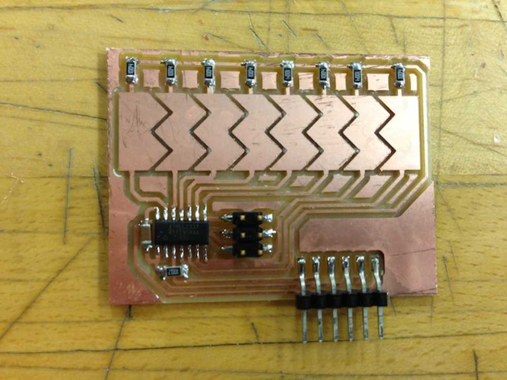
On Akash’s board you see that he has his touchpad as part of the board. This is different from Frank who has an external touchpad.
In Franks schematic you can see that he has a 10-pin header that he uses to connect to the external touchpad.
Akash has a similar ‘component’ on the top right, with 8 lead-outs to connect to the 8 resistors.
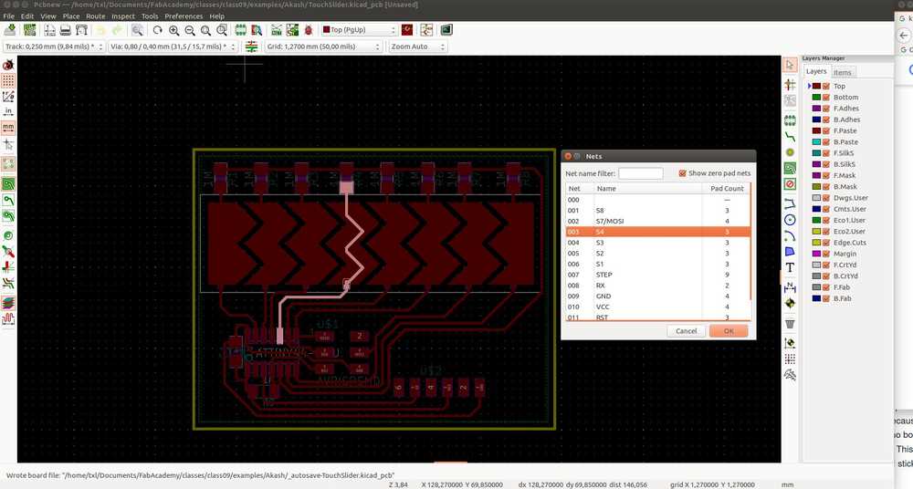
I loaded his project in KiCad (Henk showed how to do it) to find out the name of the ‘component’ but it is called touchslide. I looked through the component libraries but it isn’t in there. Maybe he designed it himself. I then looked the net list. When you select one of the 8 touchpads you can see that the trace is connected from the IC to a pad and to a resistor. So maybe the ‘component’ is just 8 solder pads. And the touchpads are just extra large traces.
I am going to try doing this by using the generic 1x8 male connector from the library.
After I run into some more problems with Akash’s design I decide to go with Frank’s one instead.
KiCad
Eeschema
I’ll also use my own documentation of week 06 Electronics Design to make this week’s design.
- Adding the FabLab library to the project specific library of my new project.
- Placing the components from the component table in the schematic.
- Go to the
Eeschemaworkbench of KiCad and select theplace symbolicon on the right of the panel. - Make sure to start with
fabwhen looking for components so the fab library is selected. - Name the components.
- Do the wiring.
- Add the footprints.
- Run the Electricical Rules Check. I have two errors:
pin connected to other pins but not driven by any pin.This is the power error I also had in week 06. Then in was not a problem. So I leave them.
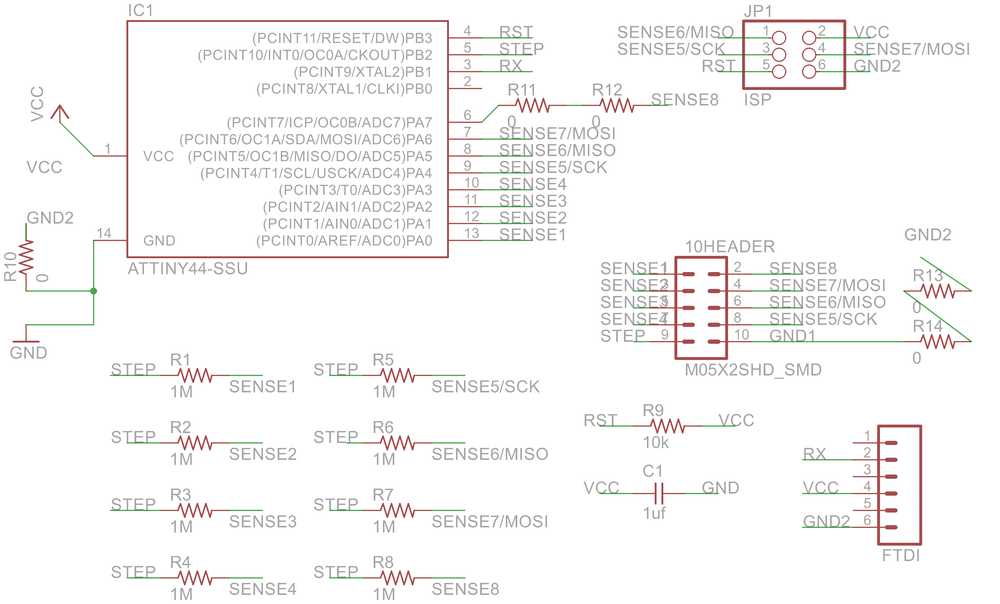
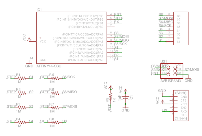
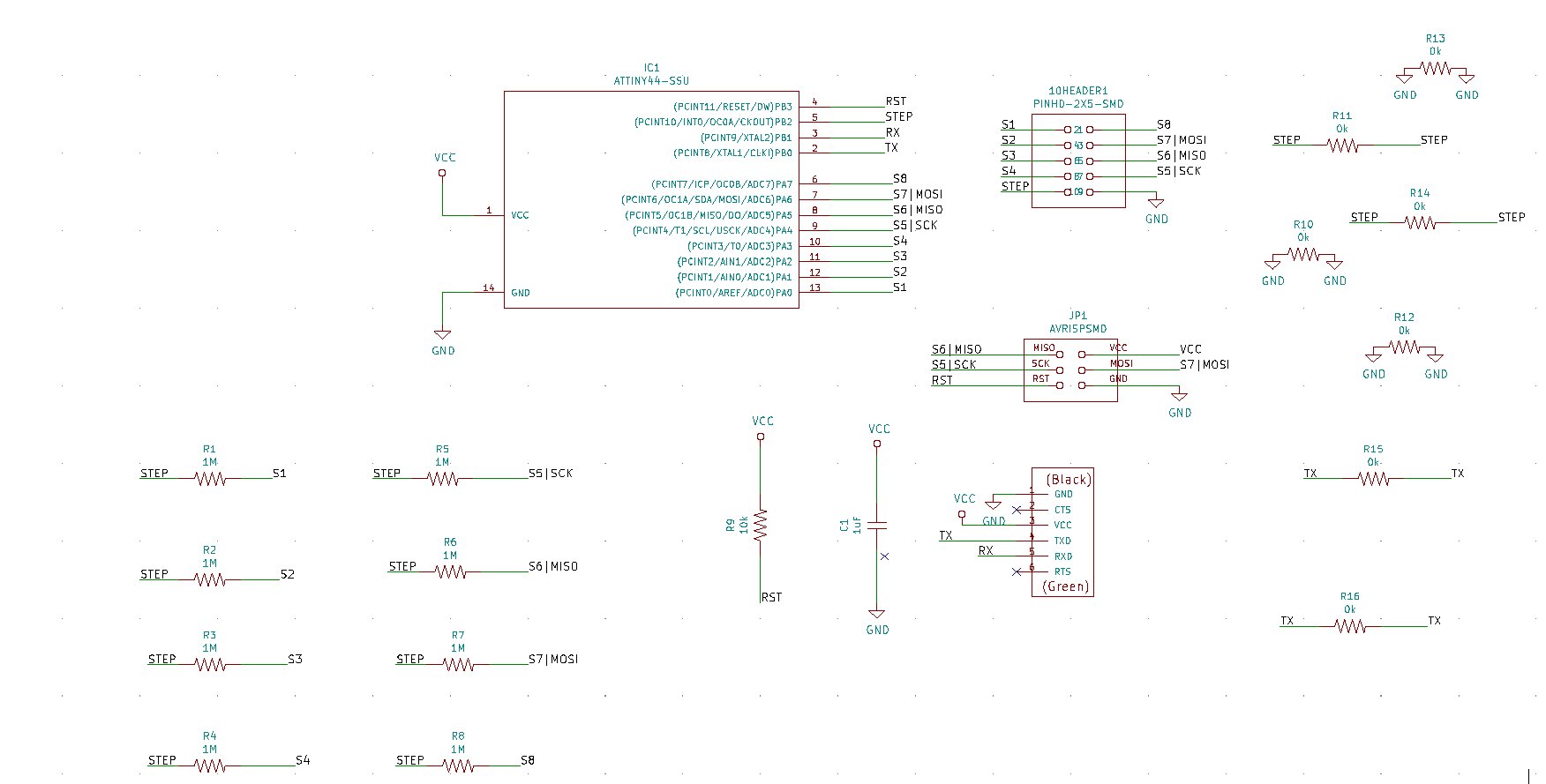
My first schematic
PCBnew
I tried to use Freerouter as I did in week06. I exported a .dsn file from PCBnew and imported it in Freerouter. But Freerouter could not read the file properly. It would load but the components would not be visible in Freerouter. Just a blue triangle.
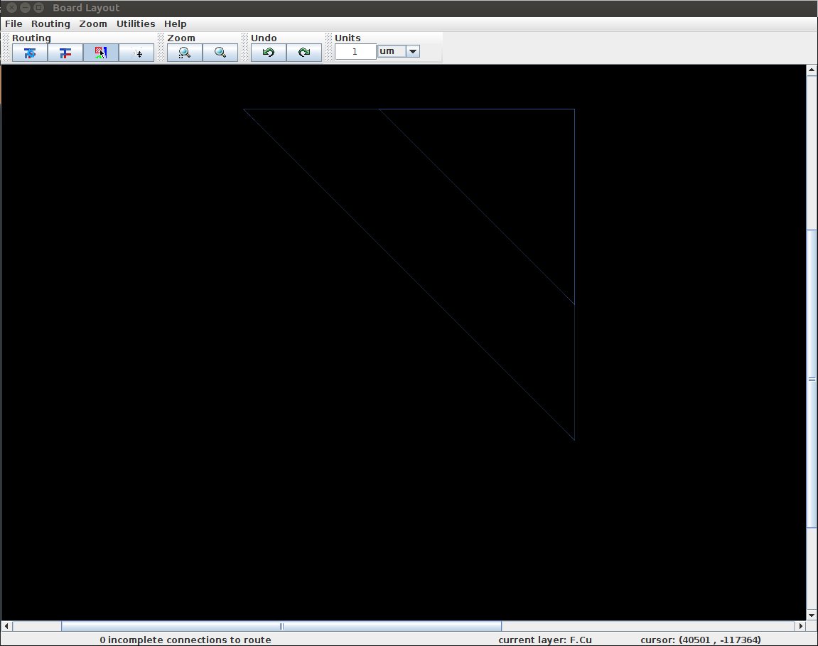
I spend a couple of hours trying to debug Freerouter without succes. I had to resign to the fact that I had to do the dreaded task of routing myself. I spend an entire day on routing and it was quite frustrating. Not so much the routing itself but the numerous hours ticking away while there is so much more work to do. But in the end I am glad I did it. It gives yet another insight into how electronics work. I can imagine a second time will go faster. And don’t give in to the hubris of not wanting to use 0K resistors as bridges to jump of the traces. Having said that, I will admit that if Freerouter wants to give me a hand next time I will certainly take it.
In the end I used 7 0K resistors as jumpers. It was a bit confusing because PCBnew indicated that the bridge itself needs a trace. So rather then serving as a bridge, the 0k resitor is now displayed as an extra unrouted trace. I asked Henk if this was a problem but he said it was not.
I made the same board as Frank and Micky and theirs do not contain an RX trace. Henk told me to add the RX trace because it enables you to communicate to the board. Which can come in handy when you need to debug. So I added a RX trace.
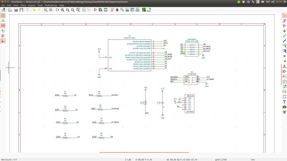
This is my final schematic:
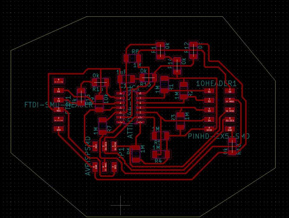
My final PCBnew:
The board’s traces file:
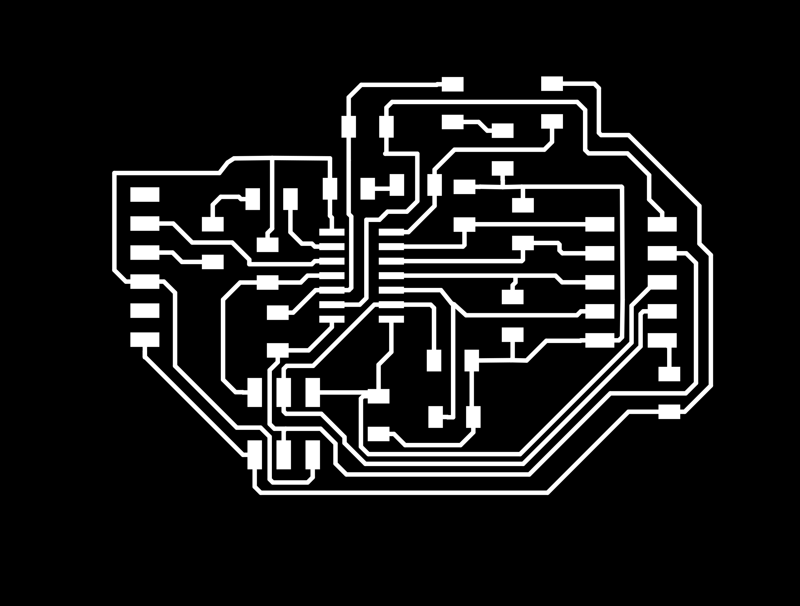
And the board’s cutout file:

Milling
I sent Henk the files to mill the board. He let me know that you can’t use .JPG for the milling machine. It must be either .SVG or .PNG because those file formats have higher resolution.
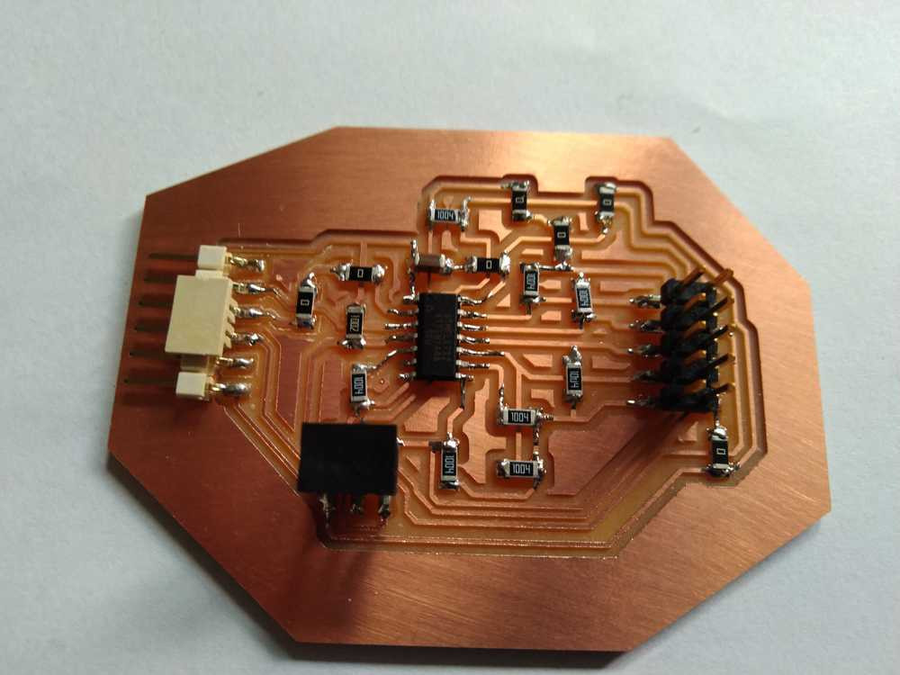
The board comes out nice
And the soldering goes well
Programming
I first test if my computer recognizes the board. I connect the sensor board to the USBtinyISP we made in week 04. I had to find the right way to connect the cable on the 6-pin headers. I look up pin 1 / MISO pin on the tinyISP and look at my PCBnew file to locate the MISO pin on the sensor board. Its the pin closest to the chip. I run:
avrdude -c usbtiny -p t44
And the output is:
avrdude: AVR device initialized and ready to accept instructions

Reading | ################################################## | 100% 0.00s

avrdude: Device signature = 0x1e9207 (probably t44)

avrdude: safemode: Fuses OK (E:FF, H:DF, L:62)

avrdude done.  Thank you.
The computer recognizes my board and I can program it.
C & makefile
I looked at the code files of Matt, Akash and Frank. Compared them all and Frank and Akash had used the same code. So I used that as well.
I then used the steps from week08 to make a Makefile.
I compared the CFLAGS of my Makefile of week 08 with the Makefile of Akash for this project and they are the same.
There were some differences in the makefile of week08 and the one from Akash.
I realize there I have knowledge gaps about the:
- F_CPU
- fuses
- CFLAgs
- AVRdude flags
I did some random research to get an idea about these topics. See below.
I started reading the make manual to get a better understanding of what the program does. I want to understand the CFLAGS but I could not figure them out based on the manual.
I also want to understand the difference between the avr commands used in the two Makefiles.
avr command week08 makefile:
$(PROJECT).hex: $(PROJECT).out
avr-objcopy -O ihex $(PROJECT).out $(PROJECT).c.hex;\
and the makefile from Akash:
$(PROJECT).hex: $(PROJECT).out
avr-objcopy -j .text -O ihex $(PROJECT).out $(PROJECT).c.hex;\
There are different flags in the command. I looked at the avr-objcopy chapter of the avr manual.
What happens in this command is the creation of the .hex and .out files by Make from the C code file.
The function of avr-objcopy is: ‘The GNU objcopy utility copies the contents of an object file to another.’
F_CPU: ‘F_CPU is only a way for you to tell _delay_ms() how fast your microcontroller is running, it does not any way change the speed of the MCU’ source.
Then I decide to just run the code and see what happens.
I cd into the directory with the C code and Makefile and run make.
Output:
avr-gcc -mmcu=attiny44 -Wall -Os -DF_CPU=8000000 -I./ -o sensor.out sensor.c
sensor.c: In function ‘main’:
sensor.c:224:16: warning: ‘centroid’ may be used uninitialized in this function [-Wmaybe-uninitialized]
       centroid += i*measurements[i];
                ^
avr-objcopy -j .text -O ihex sensor.out sensor.c.hex;\
   avr-size --mcu=attiny44 --format=avr sensor.out
AVR Memory Usage
----------------
Device: attiny44

Program:     984 bytes (24.0% Full)
(.text + .data + .bootloader)

Data:          0 bytes (0.0% Full)
(.data + .bss + .noinit)
I have to look into this part:
sensor.c: In function ‘main’:
sensor.c:224:16: warning: ‘centroid’ may be used uninitialized in this function [-Wmaybe-uninitialized]
       centroid += i*measurements[i];
                ^
I run avrdude -p t44 -c usbtiny -U flash:w:$(PROJECT).c.hex from the make file in the console. and AVRdude gives the right output. The device is now programmed.
I then run the fuses command:
avrdude -p t44 -c usbtiny -U lfuse:w:0x62:m -U hfuse:w:0xdf:m -U efuse:w:0xff:m
The next step is to see if I can get output to a serial monitor. Using screen to connect to a serial console
The others used this command:
screen /dev/[You're USB Port Name Here] 9600
I spend a long time searching the internet on how to find the USB port.
In the end I asked Henk over Slack and he simply answered:
To find the USB port name type dmesg.
And that works.
That puzzled me because I had tried dmesg during my search but then there was no mention of the ttyUSB port. I later discovered what the mistake was. When I ran dmesg the first time I had it still plugged into the ISP. When you run dmesg it will output:
[14490.185153] usb 1-1: USB disconnect, device number 7
[14492.403981] usb 1-1: new low-speed USB device number 8 using xhci_hcd
[14492.591955] usb 1-1: New USB device found, idVendor=1781, idProduct=0c9f
[14492.591976] usb 1-1: New USB device strings: Mfr=0, Product=2, SerialNumber=0
[14492.591991] usb 1-1: Product: USBtinySPI
[14492.592623] usb 1-1: ep 0x81 - rounding interval to 64 microframes, ep desc says 80 microframes
[14518.282141] usb 1-1: USB disconnect, device number 8
[14518.876746] usb 1-1: new low-speed USB device number 9 using xhci_hcd
[14519.066516] usb 1-1: New USB device found, idVendor=1781, idProduct=0c9f
[14519.066521] usb 1-1: New USB device strings: Mfr=0, Product=2, SerialNumber=0
[14519.066524] usb 1-1: Product: USBtinySPI
[14519.066875] usb 1-1: ep 0x81 - rounding interval to 64 microframes, ep desc says 80 microframes
[14553.201848] usb 1-1: USB disconnect, device number 9
[14557.294044] usb 1-1: new low-speed USB device number 10 using xhci_hcd
[14557.482749] usb 1-1: New USB device found, idVendor=1781, idProduct=0c9f
[14557.482765] usb 1-1: New USB device strings: Mfr=0, Product=2, SerialNumber=0
[14557.482774] usb 1-1: Product: USBtinySPI
[14557.483269] usb 1-1: ep 0x81 - rounding interval to 64 microframes, ep desc says 80 microframes
[14612.933159] usb 1-1: USB disconnect, device number 10
[14615.876366] usb 1-1: new low-speed USB device number 11 using xhci_hcd
[14616.066097] usb 1-1: New USB device found, idVendor=1781, idProduct=0c9f
[14616.066102] usb 1-1: New USB device strings: Mfr=0, Product=2, SerialNumber=0
[14616.066105] usb 1-1: Product: USBtinySPI
[14616.066403] usb 1-1: ep 0x81 - rounding interval to 64 microframes, ep desc says 80 microframes
When you connect to the FTDI it will output:
[15139.304990] ftdi_sio 1-1:1.0: FTDI USB Serial Device converter detected
[15139.305222] usb 1-1: Detected FT-X
[15139.305703] usb 1-1: FTDI USB Serial Device converter now attached to ttyUSB0
Thus I learned that the ttyUSB refers not to a USB port in general but to one that is connected to a serial device. A quick search on the internet confirms that dev\tty is indeed about serial devices.
I entered screen /dev/ttyUSB0 9600 but did not get a read-out:
To exit Screen press CTRL-a d.
I wanted to know if I use screen wrong. So via my class mate’s Nathan’s page I found Python code for serial monitor made by Neil. I downloaded it, cd’d into the right directory and ran: python code.py /dev/ttyUSB0. This launched the monitor but there was no response to my copper pads.
I also tried GtkTerm a simple monitor to communicate with a serial port. It has a GUI. Here there was no signal either.
Time to debug
Debugging table
| Description | status |
|---|---|
| HARDWARE | … |
| wire | |
| tx added to my board but not in the code of the project examples | This should not be a problem according to Henk |
| Not connected correctly to copper pads. | |
| SOFTWARE | … |
| try different code | Tried echo code, the one time I succeeded there was no read-out from the sensor. |
| pinout wrong | checked, probably not. |
The monitor works but won’t read any data:
python code.py /dev/ttyUSB0
Exception in Tkinter callback
Traceback (most recent call last):
  File "/usr/lib/python2.7/lib-tk/Tkinter.py", line 1540, in __call__
    return self.func(*args)
  File "/usr/lib/python2.7/lib-tk/Tkinter.py", line 590, in callit
    func(*args)
  File "code.py", line 39, in idle
    byte4 = ord(ser.read())
  File "/usr/lib/python2.7/dist-packages/serial/serialposix.py", line 495, in read
    raise SerialException('device reports readiness to read but returned no data (device disconnected or multiple access on port?)')
SerialException: device reports readiness to read but returned no data (device disconnected or multiple access on port?)
I exit Python, try to connect again but then the output is:
serial.serialutil.SerialException: [Errno 2] could not open port /dev/ttyUSB0: [Errno 2] No such file or directory: '/dev/ttyUSB0'
dmesg showed that the device had moved from ttyUSB0 to ttyUSB1. This can happen after you unplug and replug the board: the board is assigned a new port. So always check the serial port again after unplugging.
There are no error messages that tell me anything.
I decided to take the exact same steps as Micky did:
make -f [name Make file]
sudo make -f [name Make file] program-fuses
sudo make -f [name Make file] program
screen /dev/[You're USB Port Name Here] 9600
But that did not work. I looked at other pages of FabAcademy students who were trouble shooting this particular board. SamSpaulding’s timing was off. He changed the delay to 103 instead of 100. I want to try that too but after I upload the code the device is not recognized again. It alternates between being recognized and not being recognized. A loose wire maybe?
I reprogram it with the original code with delay set to 100 but the board is still not being recognized. I tried different environments:
Screen: no such file or directory.
Arduino IDE: Board at /dev/ttyUSB0 is not available.
Gtkterm: control signal read input/output error
Then I tried: sudo dmesg -c this is supposed to clear the dmesg logs so you can see fresh input.
At this point I am debugging two problems at once. The main one is why I get no output data. But in the mean time the board stops being recognized by all serial monitors accept the Python monitor. This process of deterioration will continue to haunt this project. Trying to debug the main problem, the board throws all kinds of errors of things that were working previously.
I check if it will connect to Neil’s Python monitor. It does. When I unplug the board the Python monitor says it does not recognize it. So the Python monitor does recognize the board but it still records no input.
dmesg then outputs
[23007.962914] usb 1-1: new full-speed USB device number 21 using xhci_hcd
[23008.155818] usb 1-1: New USB device found, idVendor=0403, idProduct=6015
[23008.155835] usb 1-1: New USB device strings: Mfr=1, Product=2, SerialNumber=3
[23008.155846] usb 1-1: Product: FT230X Basic UART
[23008.155856] usb 1-1: Manufacturer: FTDI
[23008.155865] usb 1-1: SerialNumber: D307S1L9
[23008.160245] ftdi_sio 1-1:1.0: FTDI USB Serial Device converter detected
[23008.160444] usb 1-1: Detected FT-X
[23008.161139] usb 1-1: FTDI USB Serial Device converter now attached to ttyUSB3
I later find out that two things are happening:
1. During debugging I unplugged the USB cable many times. This will sometimes cause the OS to assign a new USB port. In the above dmesg output, it states that the FTDI is assigned ttyUSB3. Besides dmesg the command ls /dev/tty* is also relevant here. It shows the directory with all the tty ports. Here I saw for instance that there was no ttyUSB0 listed anymore.
Once your stuck on USB3 and want to go back to USB0 port, restart the computer. Maybe there are more elagant ways to do this, but restarting works.
2. The second cause of many errors was switching between different serial monitor environments. Once you opened the USB port with one the others won’t recognize the port anymore. Even after you close the previously used monitor. The Python monitor is the only one that keeps marching on no matter what :).
Now that this is clear I go back to to the main problem: no output from the sensor to the serial monitor.
The error message in the Python monitor reads:
SerialException: device reports readiness to read but returned no data (device disconnected or multiple access on port?)
I run this error through the FabLab search engine. No one has that particular error but the query SerialException does return many hits. But for most students tha problem is that the port is not recognized at all. That is not the problem I am dealing with.
I don’t have any debugging tools, oscillator, multimeter etc. and the programs do not give much in the form of error messages either. So I am a bit stuck now. From here on out it is guess work:
I check if it is something with the pinout. Helpful to read was krasser’s page. He or she put a lot of work in putting the pins right.
I list my pins for clearity but there is nothing wrong with them. Or rather, they are exactly the same as the example projects and I am using their code. So it probably isn’t the pin out.
S1 = PA0
S2 = PA1
S3 = PA2
S4 = PA3
S5 | SCK = PA4
S6 | MISO = PA5
S7 | MOSI = PA6
S8 = PA7
TX = PB0
RX = PB1
STEP = PB2
RST = PB3
Henk helped me remotely and recommended to install the echo program made by Neil onto the step response board. That way I can test if the serial monitor communicates output.
To use the echo program as a debugging tool I first have to determine which pins correspond to tx and rx.
#define serial_pin_in (1 << PB1)
#define serial_pin_out (1 << PB0)
I then have to find out how you input to the board using a serial monitor. I haven’t used the echo program before. In the screen setup I used for a serial monitor I do not see a way to input data into the board. So I decide to use Arduino IDE. At the top of the serial monitor there is a little window with a send button. I’m assuming that is an input window talking to the board. This is the correct assumption based on an explanation of the serial monitor on Instructables.com.
To uploading the Echo code I run:
sudo make -f makefile program-fuses
AVRdude responds:
make: *** No rule to make target 'program-fuses'. Stop.
I remember this from week06. It means using the make command does not automatically execute AVRdude commands in the makefile. Like in week06 I just run the AVRdude commands written in the Makefile mannually in the terminal:
avrdude -p t44 -P usb -c usbtiny -U flash:w:$(PROJECT).c.hex &
avrdude -p t44 -P usb -c usbtiny -U lfuse:w:0x5E:m
The upload is succesful but there is no read-out on the serial monitor. I enter letters in the send box but they aren’t echo’d. So now I have to debug the echo code. Maybe I got the pinout wrong. I swop the pins:
#define serial_pin_in (1 << PB0)
#define serial_pin_out (1 << PB1)
And run the programming proces again. The output is an error. The board is no longer recognized.
avrdude: initialization failed, rc=-1
         Double check connections and try again, or use -F to override
         this check.


avrdude done.  Thank you.
I tried to flash the sensor code on the board because I knew that had worked earlier. But I got the same error message. The board can’t be programmed anymore.
So now I’m at a point where debugging attempts are only making my board worse. Flashing the echo code was an attempt to determine whether the FTDI was working. But doing that has led to the ISP programming process now also being broken.
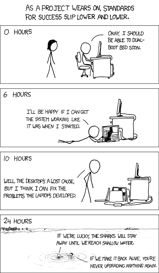
The situation is adequately described in this XKCD.
Here someone documents the same error being the result of his pinout being wrong. He has to remake the board…
- I also find in the FabLab archives:
-
‘AVRdude errors:
=> avrdude: initialization failed, rc=-1 Double check connections and try again, or use -F to override this check.-
This response from AVRdude means that it can talk to the programmer but the programmer can’t talk to the chip. Troubleshoot: https://learn.adafruit.com/usbtinyisp/help. don’t have power to the chip, when any of the RESET, MISO, MOSI, or SCK lines aren’t connected properly, or even if you’ve got something else plugged into any of these pins that’s interfering with your setup.’
It is unlikely that suddenly connections have come loose. And when I try the ISP on another board it is recognized The most likely option is the IC is bricked. This is probably the result of setting the fuses. But I have too little knowledge to know what went wrong exactly.
It is now the end of the week so I am finalizing my documentation with the ‘what went wrong header’. Documenation will continue below because I kept trying to fix this sensor board in subsequent weeks.
What went wrong
Much went wrong. The project was hampered by multiple mistakes such as the dmesg command used with the ISP plugged in and the use of multiple environments that made the device unavailable to all. In the end debugging led to bricking the IC. It has probably to do with fuses. The next step is to replace the IC and be back at the non-working serial monitor at the beginning of the debugging process.
What I learned
The mistakes along the way did shed light on concepts that we used a lot in previous classes but still weren’t entirely clear to me. The mistakes led me to understand ISP’s, FTDI and serial communication. It showed holes in my knowledge.
Continuing to try and finish the assignment
I am going to try to finish the assignment by taking a step back. Rather then using the step response board I return to the board I made in week six with the photosensor. I uploaded the code I used in week 08 to the IC to make the photosensor work. It did work but when I opened the serial monitor there was no output.
I tried reproducing the group assignment to see if the serial monitor works. It does. My photosensor board is recognized by the Arduino IDE because I just programmed it.
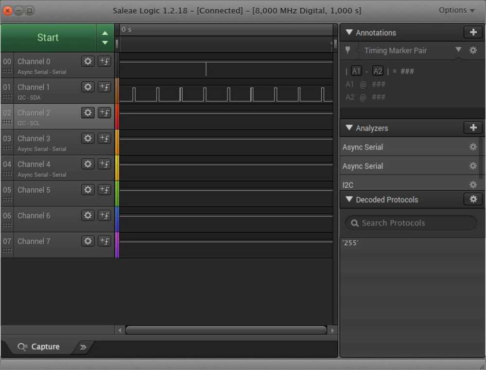
I am going to use my newly bought logical analyzer to see if there is any data coming out of my lightsensor board. It’s a Saleae logical analyzer clone. You can download the Saleae software here:
Here is the manual for the analyzer, it came for free with the device.
It says: ‘Before using the software with Logic hardware, you’ll need to give the application permission to access the device (otherwise you’ll have to launch the application with sudo). To do this, unplug any attached Logic device(s). From the command line, navigate to the Driver folder and run the script installdriver.sh.’
Go to the directory with the software in it. Cd into Drivers and then run: ./install_driver.sh
To run the software, click on Logic in the software directory.
On the right side of the software panel, click the ‘+’ next to the ‘Analyzer’, here you must select the right analyzer.
I try it on the NodeMCU with Ultrasonic sensor because I know it gives a signal because there is a readout in the serial monitor. (I’m not sure if the Analyzer was on Async serial or IC2.) I put the probe on the D1 pin of the NodeMCU. At first the software prompts: the bit rate is too high. When I select use autobaud I get a signal.
My first logical analyzer read out
I load the Blink code on my LED/lightsensor board because that is a clear signal. Channel 1 is on I2C. I put the probe on the IC pin that leads out to the blinking LED. And I get a read out.
I try the same setup but now with the probe pin on channel 0 which is set to Async Serial.

This works too
Then I load the lightsensor code onto the board. Put the probe on the IC pin connected to the lightsensor. I measure with channel 1 probe (I2C) and get a result.
I change the duration of the capture to 10 seconds under options > preferences. The options are on the top right of the panel.
This is not the right way to change duration, it turns out. Instead you should click on the arrows next to the start button and change Duration there.
This output seems too regular to be reflecting me shining a light on the light sensor rather randomly.

But it is the reaction to the light indeed. When I take another measurement and only flash the light once, there is only one output. Channel 0 on Async Serial also works.
So the setup works. Now I want to know if I have data coming out of my FTDI pin head. I upload Blink again and connect my LED/lightsensor board to the FTDI board.
Looking at the schematic of the board I made in week06, I see that tx and rx are the 4th and 5th pin respectively when counting from GND. With the LED blinking I set my channel 1 probe (IC2) on the tx pin. Nothing.
On the IC pin leading out to tx, nothing.
Nothing for rx either.
And then I try to send some data from the Arduino monitor. Place the probe on the tx pin of the FTDI and then there is a readout.
Probably a glitch because I can’t reproduce it.
Later I find out what went wrong: Henk told me that the board won’t ‘just’ start talking to the serial monitor. You have to tell it to do so in your program. That makes sense of course. At this point I have to move on to the next assignment. And I leave it for a while.
Reading a photosensor
Some weeks later: I still have to finish this assignment. Since, I learned new things about serial communication. Hopefully it will help me debug my board. But first I’ll try and have a read out of the photosensor.
I know now that I first have to load a program onto the photosensor board that tells the IC to communicate over the serial port. Another hint Henk gave me is that many people have the TX and RX wrong. So I start with check that last possible mistake.
The TX and RX on the FTDI header are correct as these are always the same. I compared against the symbolic representation in KiCad and they are placed correctly.
Next I look into the datasheet of the ATtiny44 to check out the pinout for TX and RX. TX and RX aren’t hardwired in the ATtiny, you can define them in the code. So this is not the problem.
I take the Hello Echo board with the light sensor on it. I have code that makes the light sensor work. And if I succeed in adding commands for serial communication in the code I should be able to read the sensor in the serial monitor.
This is the code for operating the photosensor.
// On-Board LED and Phototransistor. Adapted from code from Arduino forum https://forum.arduino.cc/index.php?topic=3636.0

int analogPin=2; //phototransistor connected to analog pin 2
int ledPin=7; //led is connected to pin 7 (on-board led)
int voltm=0;

void setup()
{pinMode(ledPin,OUTPUT);


}

void loop()
{voltm=analogRead(analogPin); //read the phototransistor
if (voltm<650)
{digitalWrite(ledPin,HIGH);}
else
{digitalWrite(ledPin,LOW);}
}
I upload the code to test. It works. Then I want to upload adjusted code. And my ISP has disapeared. It is no longer recognized by the Arduino IDE. Under tools > port the port is grayed out.
Debugging:
To test if there is something wrong with the Arduino IDE I hook up the Arduino device. It works with the IDE so this is not the bug.
I test if UDPI still works with Arduino IDE. It does.
I test if AVRdude finds the board. It does. I succesfully load the blink code from week08 onto the board.
So it isn’t the wires, or the cables.
Just for the sake of it, I hit Upload in the Arduino IDE. And it uploads. o_0.
What may have been the case: I am now used to having to select ports. But maybe the ISP does not need to have a port selected in the Arduino IDE. At least not manually under the tools drop-down menu. Because for the rest of the time, I can upload over the ISP while the port section in the Arduino IDE is grayed out.
So onwards, I want to add serial communication code to the lightsensor code. I try some simple code with serial.begin. I receive error: 'serial' was not declared in this scope. I include the library SoftwareSerial.h but I get the same error. On the Arduino forum someone explains the code should be different.
Rather then the more common serial command, you have to use mySerial. It works to replace all serial commands for mySerial. In this setup you also need to define your RX and TX in. This is done in he second and third line of the code. I look in the datasheet of the ATtiny44 and at my KiCad Eschema and determine rx=0 and tx=1.
#include <SoftwareSerial.h>
const int rx=3; //define rx pin
const int tx=4; //define tx pin

SoftwareSerial mySerial(rx,tx);

void setup()
{
mySerial.begin(9600);
}
Based on this tutorial I get the hello echo code to work:
#include <SoftwareSerial.h>
const int rx=0;
const int tx=1;

SoftwareSerial mySerial(rx,tx);
int i=0;
char buf[12];

void setup()
{
pinMode(rx,INPUT);
pinMode(tx,OUTPUT);
mySerial.begin(9600);
}

void loop()
{
if (mySerial.available()>0){
buf[i]= mySerial.read();
if (int(buf[i])==13 || int(buf[i])==10 ){ //If Carriage return has been reached
mySerial.println(buf);
for(int x=0;x<=10;x++){
buf[x]=' ';
}
i=0; //start over again

} //if enter
i++;
} //If mySerial.available
}//LOOP
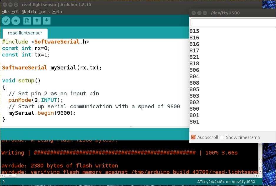
Then I adjust code taken from this Instructables example and turn it into this:
#include <SoftwareSerial.h>
const int rx=0;
const int tx=1;

SoftwareSerial mySerial(rx,tx);

void setup()
{
  // Set pin 2 as an input pin
  pinMode(2,INPUT);
  // Start up serial communication with a speed of 9600
  mySerial.begin(9600);
}

void loop()
{
  // Read in the current value of the light sensor
  int reading = analogRead(2);
  // Send the value that we just read down the serial connection
  mySerial.println(reading);
  // Wait for a bit, just to slow everything down
  delay(500);
}
And then I get a readout:
Try to get read out of step response sensor
So now I have been able to get a readout of a sensor over the serial port. Next I want to get a readout from my step response board.
To start I have to replace the IC. I bricked the IC some weeks back. So I desolder the IC and am soldering on a new one. Looks lovely, compared to the first try in, was it week04?, my soldering skills have much improved.
Then I check if I have the TX and RX wired correctly. I check TX and RX. Pin PB1 of the IC is connected to the RX of the FTDI. So PB1 must be transmitting = TX. This corresponds to the code #define serial_pin_out (1 << PB1).
I cable the board to the ISP and the ISP to my computer. On the other side I plug in the FTDI board and connect the FTDI to my computer’s USB port. I run: avrdude -c usbtiny -p t44. AVRdude recognizes the board.
I use Akash’s code. I cd into the directory where I stored his C code and Makefile and run:
make -f [name Make file]
sudo make -f [name Make file] program-fuses
sudo make -f [name Make file] program
screen /dev/[You're USB Port Name Here] 9600
- Then I unplug the ISP cable from the step response sensor board.
- I plug FTDI board to stepper board and run USB cable to computer.
- I run
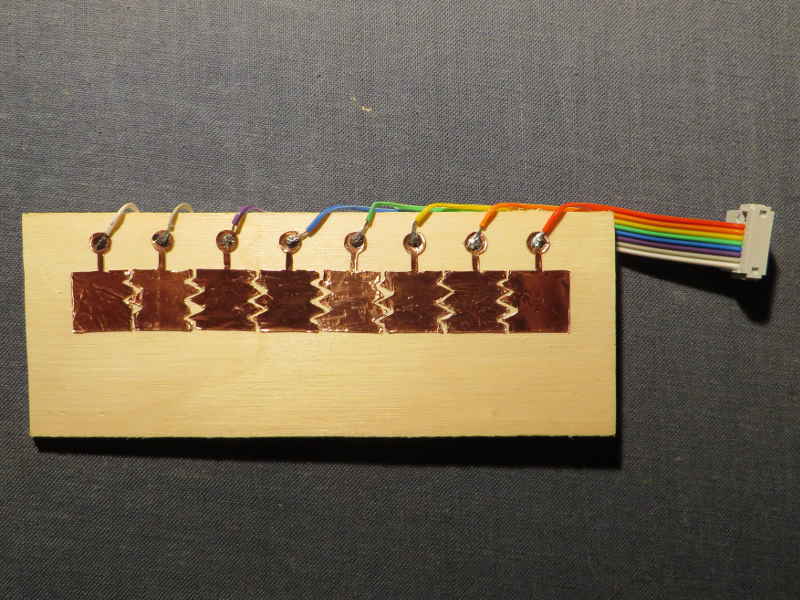
python3 -m serial.tools.list_portsto find the USB port. - I connect the ‘keyboard’ with the 10-pinheader to the stepper board.
- I run
screen /dev/[You're USB Port Name Here] 9600. - Screen should read out what the stepper board outputs over the TX pin.
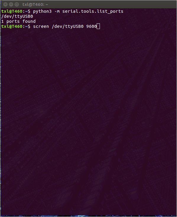
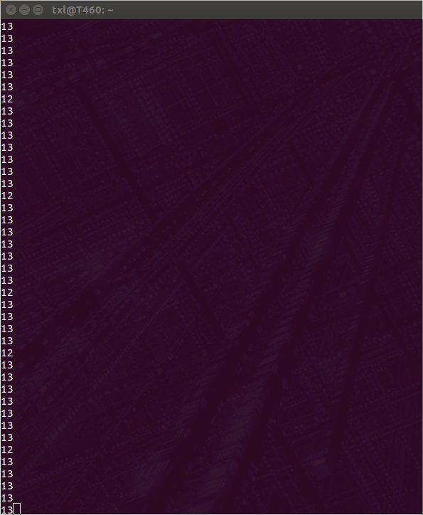
And then, finally, I have a reading. Screen outputs numbers and when I touch the copper pads, the numbers change. It just keeps running indefinitely.
To exit screen: CTRL-a CTR-d.
Be aware that if you close screen and want to run it again by simply repeating the command in the console, screen outputs: [screen is terminating].
I have to unplug and replug the USB cable before it will start reading again.
So what went wrong part II
So what went wrong? Here is what I thought at first: That before the board did work. But that I kept trying to get a readout without plugging in the FTDI cable. That sounds remarkably stupid now. But I think when I was doing this in week09 I did not understand serial communication, the ISP and the FTDI. Not in the way I understand it now.
So that’s what I thought went wrong. But when I read back my documentation I did plug in the FTDI cable. So that was not it, after all. In the end I do not know what went wrong. The first time I loaded Akash code onto the board and did not get a read-out. After I bricked and replaced the IC I uploaded the same code and it worked. So, I can’t trace back what went wrong the first time.
Local lecture
ATtiny44: clock not accurate. You can fix it in software or on hardware. You have to set if you use the external clock.
Global lecture
How to bring the world into your board.
establish multiple ways to come in from the outside world.
- pins.
- comparitor: is one voltage higher or lower than the other.
- Analog Digital converter. Multiplexer. You can measure single voltage. Value can be power supply.
Look at datasheet.
Each has registers: is pin output or input.
communication: you need terminal to read your data from the
Garble communication: probably the timing is off. Look at the clocks.
Switch: simple input device.
step response to make a keyboard?
chip version A
https://randomnerdtutorials.com/rf-433mhz-transmitter-receiver-module-with-arduino/
https://www.princetronics.com/how-to-read-433-mhz-codes-w-arduino-433-mhz-receiver/ Step response to use as touch pad. Example in the week 09 global review of someone using step response to make a touch pad