11. Input devices
The individual assignment of this week is to measure something. I will add a sensor to a micro-controller board that I designed and read it. As a group assignment we measure and probe an input device’s analog levels and digital signals.
Files, planning and tools
Files
- Link to Neil’s step response file
- Link to Neil’s step response make file
- Illustrator file of board and touchpad
- PNG-files of my Tree board and touchpad
- KiCad-files of my Treeboard
- Program code used by Frank Vloet
- Makefile used by Akash Badshah
Planning
- Group assignment and documentation of the group assignment
- First I want to reproduce Neil’s step response hello board, to get a better understanding of input.
- Reproduce and program Neil’s board.
- Figure out how the step response board works and is program.
- Look into the design by Matt Blackshaw for the touch pad.
- See if I can tweak it with my own design, making my design and soldering it.
- Use the program by Neil and Matt to understand how the touchboard works.
Tools
- Eagle: to read Matt Blackshaws files
- KiCad
- Mods
- Roland Modela MDX-20
- Vinyl cutter
- Illustrator
Link with final project
For this week I want to start with my first spiral in the input design of my final project. As mentioned in my planning the first week of the Fab Academy. The main interaction I want in my artificial tree is to put it on and off with a tab and to change the intensity of the lights and movements with a stroke up or down.
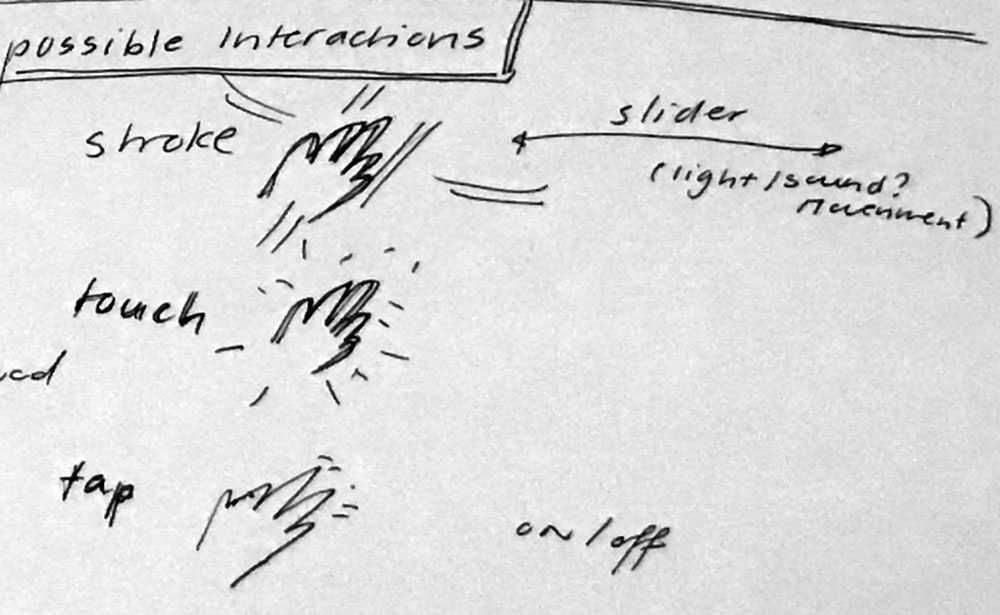 First ideas of interaction for my final project
Research and inspiration
This week I looked a lot into the documentation of previous Fab Academy students. Because the main interaction for my final project will be tabs and strokes therefore I want to use the step response as input device. For inspiration and research I started with Neil’s example board, the touchpad by Matt Blackshaw and the multitouch by Matt Keeter
Links used to documentation by previous Fabacademy students
- Matt Blackshaw’s touchpad
- Multitouch by Matt Keeter
- Fabacademy student Hyebin Goo’s page on input devices
- Fabacademy student Frank Vloet’s page on input devices
- Fabacademy student Akash Badshah’s page on input devices
- Henk’s documentation on input devices
Links on step response and other background information
- Khan Academy on the RC step response
- Arduino on Capacitive Sensor
- Recover bricked Attiny using Arduino
- Logic analyzer vs oscilloscope
- How to Use an Oscilloscope
- Analog vs digital
What we did – Group assignment step-by-step
On Thursday we did our group assignment, we used the lay-out of Henk’s board from last year to measure the device’s analog levels and digital signals.
Our first try
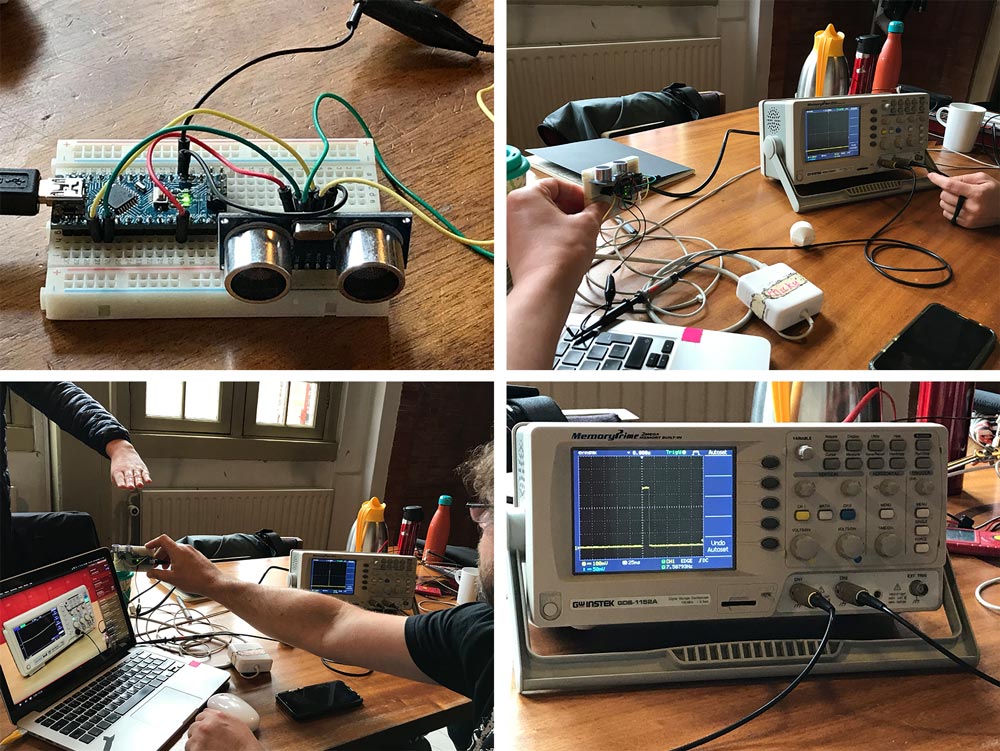
We started with connecting the probes to the board with a distance sensor. Our setup:
- Black wire to ground
- Yellow wire = echo set on channel 1
- Green wire = trigger set on channel 2
We tried to measure the signals by changing the settings on the oscilloscope with channel 1 (the yellow button)knob, this changes the voltage, we set it to 100 mV. We set the voltage of channel 2 (blue button) to 5V by turning the knob related to this channel. We tried to change a lot of setting based on [Henk’s documentation]((http://archive.fabacademy.org/2018/labs/fablabamsterdam/students/henk-buursen/week11.html) but we all didn’t really know what we’re doing and what we should see and look at. So we decided to start over, with a better plan.
Our second try
Because we didn’t really know what we were doing we decided to follow the Youtube tutorial by SparkFun Electronics about How to Use an Oscilloscope. We followed the steps described in the video
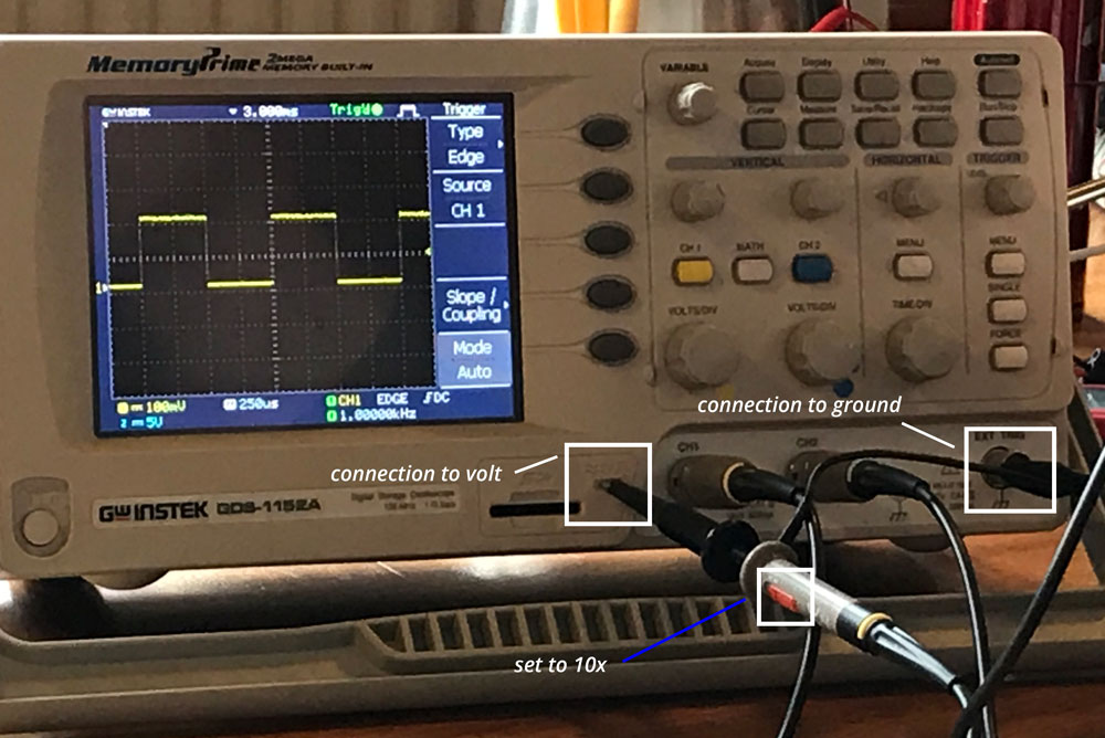
Step 1: measuring the probe
- Set probe to 10x
- Connect probe to oscilloscope on the pin sticking out of the oscilloscope and the ground to the ground
- Set oscilloscope to channel 1.
- Settings are 500 mV and 250 us
- The measurement of the signal is: width 2 squares so 500 us (microsecond and 200 mV)
- We moved the trigger line to get a stable signal
- Now we got a better understanding of the oscilloscope and have the first measurement of the probe
 Measuring the probes
Step 2: measuring the echo sensor
We decided to first measure the echo sensor (HC-SR04) on the board.
- First make sure nothing is in front of it as it measures distance. This way we have a better view of the changes in measurement.
- Connect the yellow wire (echo) to channel one.
- Press run: now it starts its measurement, but we still don’t really get the line on the screen the way we want, so we have to turn the knobs to get a beter view.
- We turn the time knob to set the time distance.
- We turn the voltage knob till we get a better image of the line. We set it on 100mV
- We turned on the vertical knob so the measurement line fits in the screen
- And we turned the trigger knob to get a stable signal.
- We managed to set all the setting on such a way that we got a nice signal. Now we can measure the distance.
- So we measure that the closer something is to the sensor the more narrow the signal is. This shows how the echo sensor is working, it sends out 8 pins and it puts the echo on high, when it gets the signal back it puts the signal back to low. That’s what we see on the screen as well when Anne puts her hand in front of it.
 Measuring the echo sensor
Step 3: measuring the trigger and the echo sensor
After we finished measuring the echo we also wanted to measure the trigger, so we could see the response of both in one screen.
- We connect the wires from the board to the probes of the oscilloscope: green wire, the trigger on channel 1 and yellow wire, the echo on channel 2. It doesn’t make a difference for the measurement but this order is more useful to visually keep track of what we’re measuring as the echo response to the trigger so we set this order.
- We followed the same steps as we did for the previous measurements.
- Now we have two lines in the screen. We see the trigger line (yellow) is a straight line and the blue line shows the echo this time.
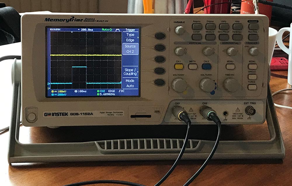 Measuring the trigger and echo sensor
Step 4: Measuring a digital signal
After measuring the analog signals we also wanted to measure the digital signal from the board. Data is transfered between the TX and RX to measure the distance. So we used these pins and the logic analyzer to see if we could measure a digital signal.
Our setup on the osciloscop
- yellow wire: RX - channel one
- green wire: TX - channel two
The yellow line shows that the line goes up and down. It shows the bits that go back and forth.
To get a better view of the data transmitted we used a logic analyzer.
- Start software Logic.
- Connect board to the computer with the logic analyzer.
- The signal sends a binary code and we used an asci-binary-table to check what is says, which is cm.
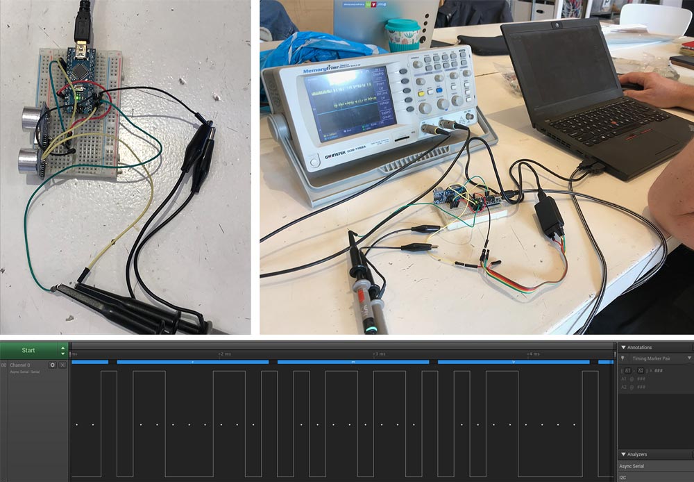 Measuring the digital signal
What I did – step-by-step
Because electronics and programming electronics is still very new for me, I used inspiration provided by the Fabacademy. Is started with ‘Neil’s board of the step response, and I first followed steps by Matt Blackshaw and Matthew Keeter.
Step 1: Reproduce the hello load board by Neil
I liked the first step by Matt Blackshaw who inspired me to make a touchpad. He first started with the board design by Neil to get a better understanding of the step response. For me it works best to experiment so this step felt good for me, I started with reproducing Neil’s board. I took these steps:
- Download the png-files by Neil
- I used Mods and the Modela to mill the board.
- Soldered the board.
- Program it. I had some problems because the commands were a bit different and because it turned out I didn’t install python. To trouble shoot this I used the documentation of former Fabacademy student Hyebin Goo’s
- Hyebin’s page gave me inspiration to connect a copper pad to each of the pins. So I followed this step as well. Which was good because it showed me what each pin measured. With as end result that the green wire works as it gives to most difference in measurement. And this is the sense pin on the board.
 First step response input measurement
Step 2: Draw and design my own touch board
While I was working on my first board by Neil, Frank Vloet who works at the Waag and did the Fab Academy in 2015, mentioned that I should look at his documentation as he did the same. He based the design of his board on the work of Akash Badshah. I looked at both designs and they have comparisons to the one by Matt Blackshaw. The biggest difference between the three of them is how they connect the touch pads to the board. Matt uses 4 pin headers, Akash places the touch pads on the board and Frank uses a 8 pin header which I find a neat solution. So my design is inspired by these boards.
- For each touch pad I need a Resistor of 1M Ohm, I want to make eight touch pads therefore I need eight 1M Ohm resistors.
- I need an FTDI-header
- I will use an ATtiny44 because I want more touch pads and the ATtiny44 has more pins than the ATtiny45
- I need an 10k resistor and an 1uF capacitor these are both for the ATtiny44.
- I need an six-pin ISP-header for the programmer.
- I will use an ten-pin header for the connection to the touch pads.
- For the ten-pin head, I will need a connector and eight wires to make a connection to the touch pads.
- I will use copper pieces for for my touchpads.
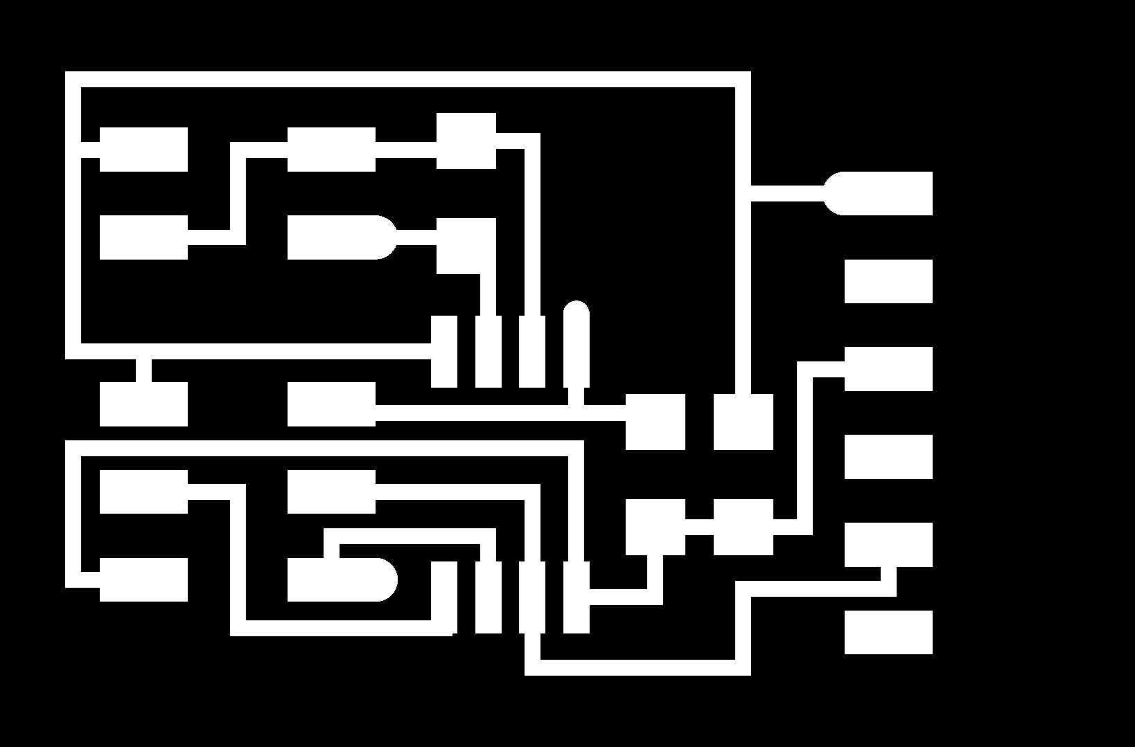
With these basic elements I first created a schematic in kiCad. I added the 0 Ohm resistor at the end.
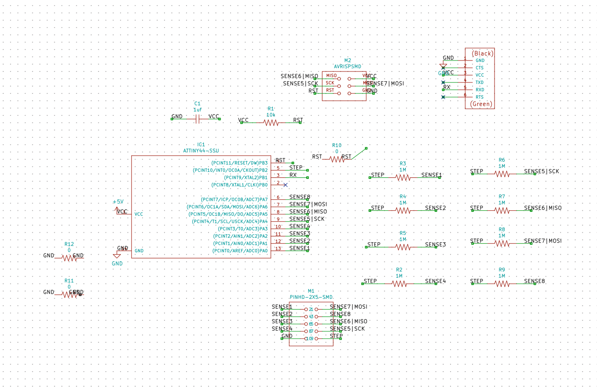 Schematics of my board
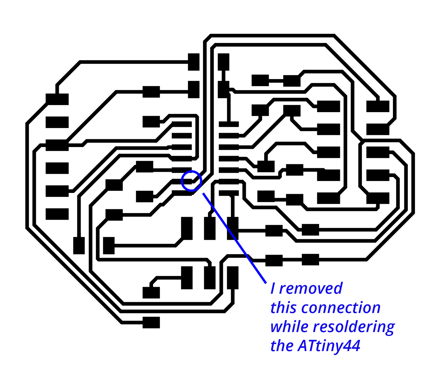
Step 3: Routing my board
The routing and design of my board took a while because I wanted to try to route my board without using an zero Ohm resistor as a bridge. All the examples I saw did use at least two zero Ohms or they used jumper wires. I set myself the challenge to do without because I really enjoyed the puzzle. When I didn’t find a solution, I first tried to change the names of the 10-pin-header however this didn’t help me as I still couldn’t find the right route to connect everything. So in the end I used two zero Ohm resistors to connect the ground and I used one for connecting the RST.
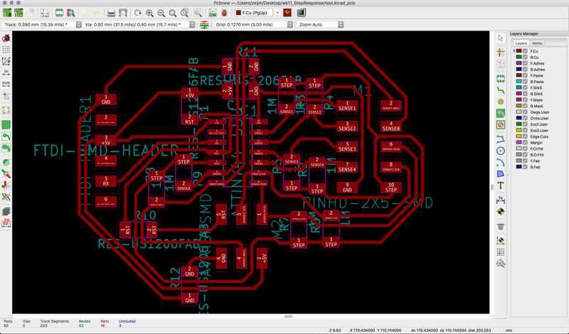 PCB design of my board
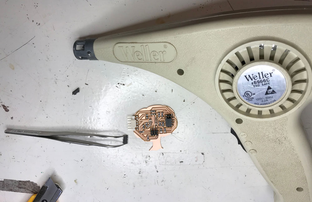
Step 4: Milling and soldering my board
The milling and soldering of my board went really smooth, I followed the steps from week 5. I created a tree shape outline for my board and for the touchpad.
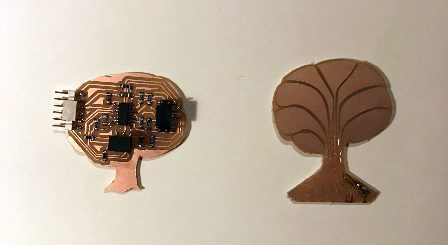 End result tree board and touchpad
Step 5: Programming my board
When I finished my board, my first step was to check if my computer can recognize it. So I used the avrdude -c usbtiny -p t44 command to check, and it had an connection which means I could program my board.
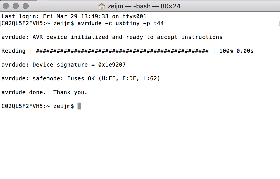 Checking the connection with my board
Using the makefile
My plan for programming my board was to follow the steps I took in week 9 because I knew those steps work with an c-file and I wanted to start with using the code Frank used as well for the first test and he only provided a c-file in his documentation.
So first I had to figure out how to compile the c-file and which makefile to use. I compared the two makefiles from Neil to see if I could understand which one I could use best. I was a bit to impatience and didn’t think it through, I decided to use the file that had an Attiny44 as well.
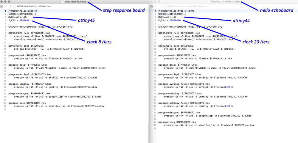 Comparing the two makefiles I used before from Neil
Bricking my board
So I used the make file of the Attiny44 and compiled it and programmed the fuses of the ATtiny44. However when I wanted to program the c-code my computer didn’t recognize the board anymore. I got the error message:
make: *** No rule to make target `program-usbtiny-fuses'. Stop.
So I googled it to find out what it means. I read that one reason for this error message is that it can’t make a connection and my chip is bricked by setting the wrong fuses. One way to brick your chip is setting the wrong clock as mentioned on electronics lab. I realized I used wrong clock setting in the makefiles. So I removed my ATtiny44 from the board and re-soldered it to be able to start over again.
Starting over
This time I looked at the documentation by Akash Badshah, he did include a make file. Before I started with using his documents I compared the programs from him and Frank to see if I could use both. They are almost simular so in the end I used the code and makefile by Akash.
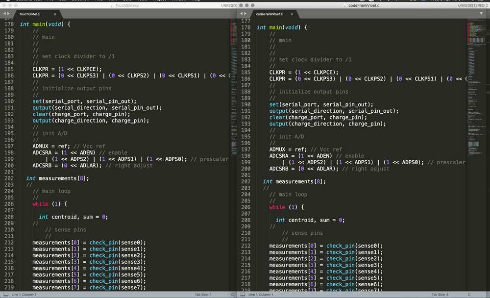 Comparing the code by Akash and Frank
I used the commands below step for step to compile, set fuses, and program the board, and to make a connection.
  make -f [name Make file]
  sudo make -f [name Make file] program-fuses
  sudo make -f [name Make file] program
  screen /dev/[You're USB Port Name Here] 9600
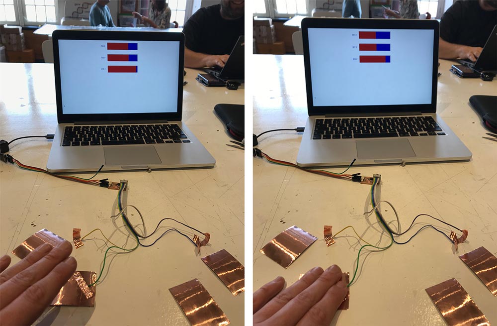
This time everything worked straight away. For start I used general copperplates to test because I would need to solder to wires to my small touchboard tree and I only have one cable with a 10-pin-header connection. But this worked and I could read the measurements from each pad. Except for one, one pad didn’t work so I to check the connection with the wire, the pins and the Attiny44. It turned out that pin 6 lost it connection to the copper.
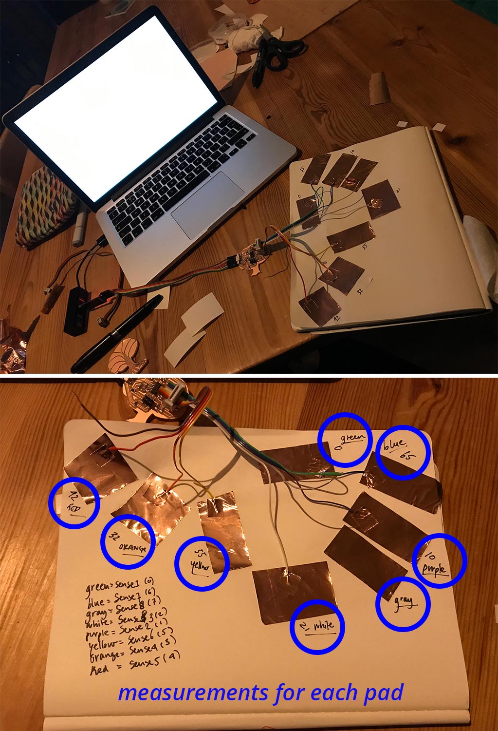 Measuring the input of the touchpad
I still have to fine tune the measurements. It prints the ports and the measure however it’s still a bit inconsistent. So for the output week I want to fine tune the measurement to get better readings and data for the output.
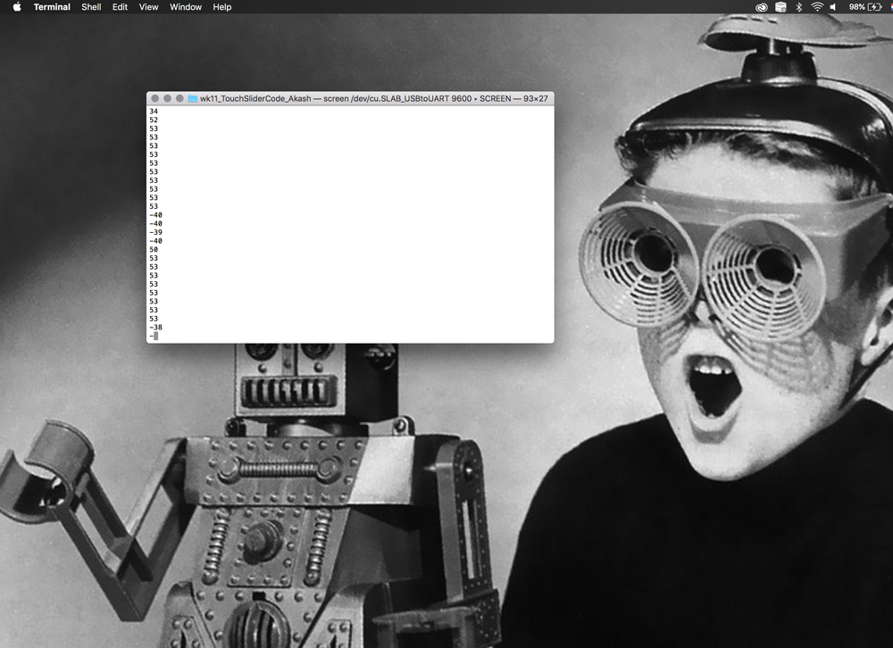 Measuring the input of the touchpad on screen
Using capacitive touch in Final Project
In the end I used the capacitive touch in my final project. More details can be found in the documenation of week 20 and of my final project
capacitive touch test with values
Making different touchpads
Because I wanted to connect this weeks assignment to my final project I created different versions of the touchpad, this way I could experiment with shape and form for a possible interaction display. I had some problem working with the copper but in the end I have to nice touchpads with only small mistakes. I didn’t have time yet to test them.
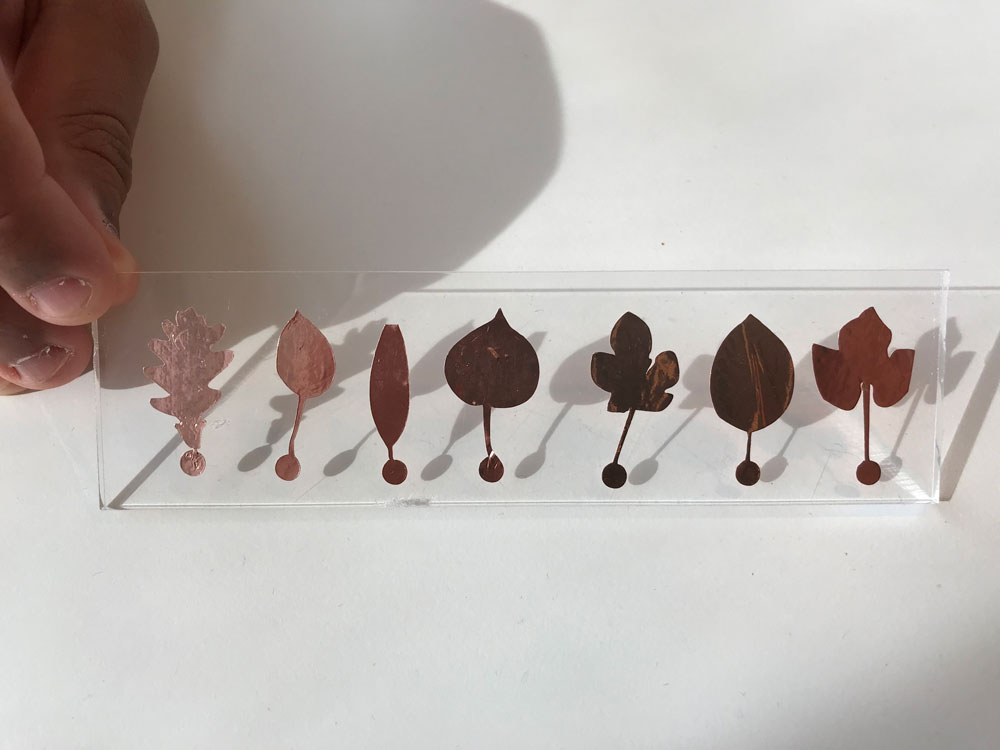 Leaf shape touchpad
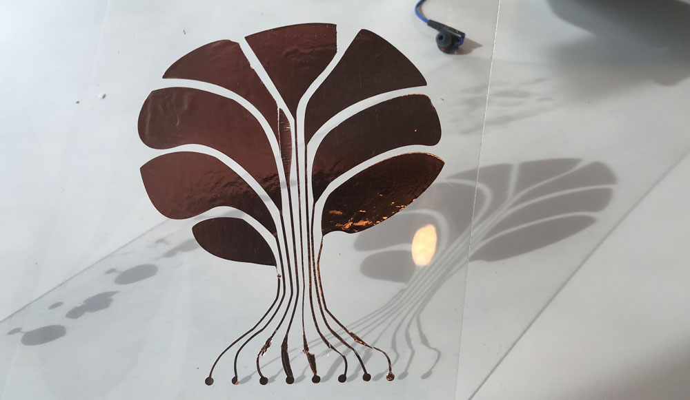 Tree shape touchpad
What I did wrong – and how I solved it
There were quite some little mistakes and that I made this week.
Python not installed
When I wanted to program and use the code by Neil somehow it didn’t work. After some research I found out that it must be my version of python. Former Fabacademy student Hyebin Goo’s mentions the same in her documentation. So I followed her step used the command sudo python setup.py install. This worked.
I bricked my Attiny44
When I programmed my chip I was a bit impatient. In the documentation of Frank I only saw a c-file not a makefile. While I knew I needed a makefile to compile the code and program the board. So I looked into Neil’s makefiles to see what the difference is between the ATtiny44 and Attiny45 makefile. I made the mistake that I only looked at the version of the Microcontroller and didn’t think of the rest of my board. Only after I set the fuses and I didn’t get an connection anymore I realized that the makefile of the Attiny44 used has a external clock and my board doesn’t have a clock of 20 Hertz. I solved this
- Removing the ATtiny44 from my board with an hot air gun.
- Removing the solder as much as possible.
- Re-soldering the ATtiny44 on my board.
 Re-soldering the ATtiny44
I lost the copper connection to pin 6
When I tested my touch board, I didn’t have a measurement from one of the pads. So I checked the connections with the pins on the Attiny, the 10-pin-header and the wires with the multimeter. There was no connection with pin 6 on the pin itself, while there was a connection with the line going under the chip, so I realized I must have removed the copper when I was cleaning the solder from my chip. This was a bit messy and I was already afraid that I might have removed a connection. I could solve this by removing the ATtiny44 again and re-soldering the connection or making a new board. Another way might be that I add some extra tin to the pin which might re-flow back to the copper connection. However for this moment and time wise I’m happy with seven touchpads instead of eight.
 I lost the copper connection to pin 6
Coppertape is really difficult to work with
Because I wanted to experiment with a flexible touchpad I used copper tape to create a tree shaped and leaf shaped touch pad with the vinyl cutter. However I didn’t realize copper is really different that vinyl to transfer it on another surface. So in the end I messed up a lot of versions because the design is to fragile, the copper wasn’t totally through and because I was impatient.
What I learned
Copying helps understanding
It really helped me this week to first reproduce Neil’s board, followed by making my own version of Frank’s and Akash’s board and use their program to compare, understand and program my board. Because both my electronics and programming skills are still really on entry level, I need these examples to get started in understanding what I’m doing.
Know your clock
I learned that the clock is a really important part of electronics and that you can really mess things up when you set the clock wrong. This happened when I set the fuses with the makefile. So for the next time make sure to know which clock to use.
What made me proud!
What made me most proud was that I figured out that I bricked my board because I used the Make file by Neil which included an external clock of 20Herz which I don’t have on my board. Eventhough I made this mistake the fact that I found the solution the moment I did it tells me I get a better understanding of electronics. I was really proud that when I resoldered the Atttiny44 it worked.
Credits and references
This week I really used the Fabacademy network to get an understanding of electronics and sensors. All the documention by former students really helped me. I used the documentation by Matt Blackshaw, Matt Keeter, Hyebin Goo, Frank Vloet and Akash Badshah.