5. Electronics production
This weeks group assignment is to characterize the design rules for our PCB production process, for this we did a line test. As individual assignment we have to make an in-circuit programmer by milling the PCB, and program it.
Files, planning and tools
Files
Planning
- do the group assignment
- document the findings of the group assignment
- create my own in-circuit programmer
- document the process and troubles developing this
- updating my final project documentation
Tools
- Roland Modela MDX-20
- 20 PCB mill
- 0.4 mm - 2 flutes mill
- 0.8 mm - 2 flutes mill
- Mods
- soldering iron
- multimeter
- tweezers
- terminal
Link with final project
This weeks assignment is not directly linked to my final project. However in the future I will use and need the FabTinyISP to be able to program circuits for my final project.
Research and inspiration
This weeks I mainly followed the tutorial by Brain Mayton and my research was mainly into trouble shooting the error I got while programming the tinyusb. However I didn’t understand most of the forum discussions about this so I mainly looked at previous Fab Academy students with the same problem. You find more information on this in the problems section
Links I used this week
- tutorial electronic production
- tutorial how to use a multimeter by makezine
- Crosspack download (MacOs)
What we did – group assignment step-by-step
We started the Thursday with a detailed lesson by Henk of our PCB machine and how to use Mods. This step-by-step approach can be found under my own individual assignment.
 Our group!
Step 1: preparing the resolution of the file
For the group assignment we first downloaded the line test file from the Fab Academy site on the desktop computer of our Fab Lab.
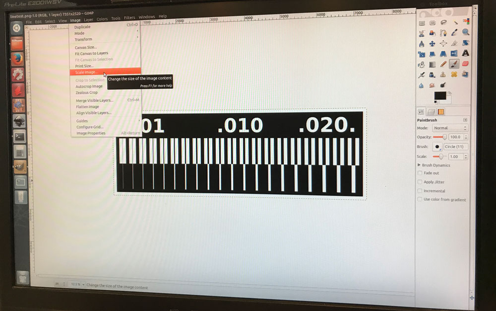 Changing resolution in GIMP
We had to change the resolution this png to 1000 px/in, otherwise our machine would not be able to process it. The original file was 5000 px/in. Rutger and I tried to change this in Gimp. We’re both not used to Gimp so it took us a while to figure out how this would work. We managed to find the scale setting and we changed the resolution from 5000 to 1000 px/in. However this changed the size of the image as well. Both the scale and the print setting in Gimp did the same thing. In the meantime Anne tried the same in illustrator and she managed to change the resolution without changing the size of the file. So in the end we used her document for this test.
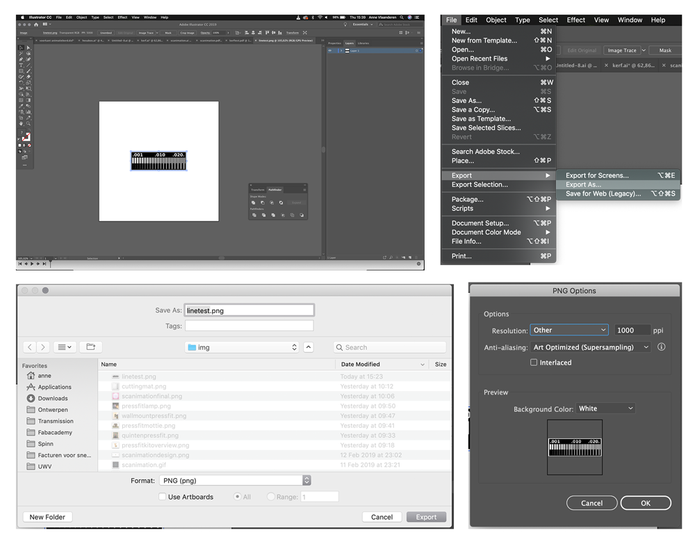 Changing resolution in Illustration by Anne
Step 2: preparing the machine
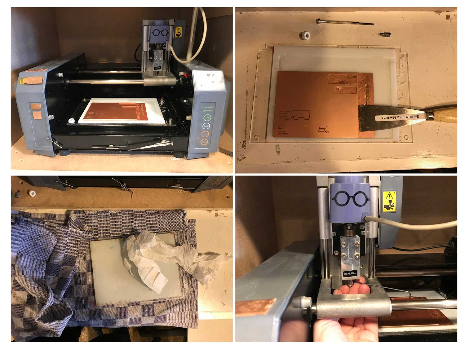
Together we repeated the steps we learned this morning from Henk. I described these steps in detail for my own individual assignment. While we reproduced each step we told Joey what to do as he was handling the machine. The machine we use is a Roland Modela MDX-20 small milling machine. You can use it for precision 3D milling and 3D scanning, as well as for circuit board milling. At the Waag Fablab we mainly use the milling machine for circuit board milling as milling other material gives a lot of dust and is difficult to keep clean. The working area of the milling machine is 200 mm by 160 mm, you can use different file formats for the milling machine. However we mainly use png and Mods.
 We helped Joey to set up the PCB machine before milling
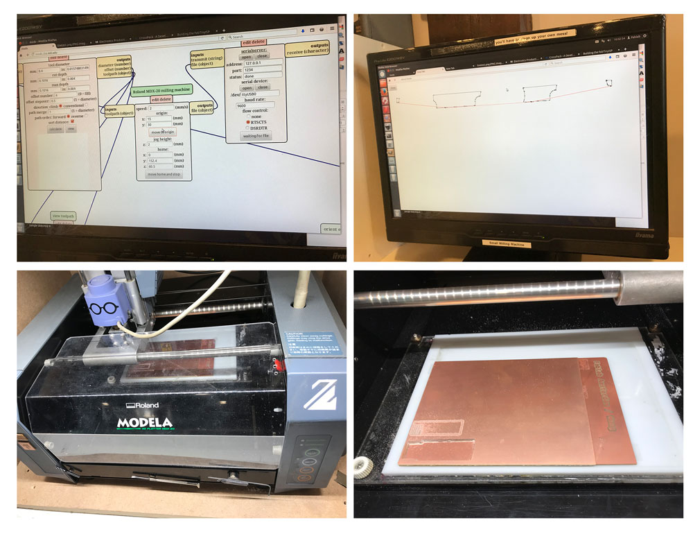
Step 3: using Mods to send the file to the PCB
After setting up the machine. We set everything up in Mods. First right click select programs > open server program > Roland mill MDX-20 PCB. Steps we took from there.
- Read png: select the line test file from Anne.
- Set PCB defaults: select the option mill traces, we’re going to test the setting of the traces of the mill.
- Mill raster 2D: we set the tool diameter to 0.4 mm > the offset stayed at 0.4 and 0.5 step over
- Roland MDX milling machine: we set the speed to: 2 mm/s and the origin x: 15 and y: 30 (which we later changed to x:15 to y:27 to save material)
- Web socket terminal: to be able to make a connection with the machine, we first clicked on the serialserver.sh icon on the desktop. This established a connection. After that we opened the serial device followed by the serial server. Now the Roland MDX PCB and Mods have a connection.
- Mill raster 2D: click calculate: We had a group discussion after we pressed calculate as we saw another view of the file than we thought we would see. So we made changes in the offset as we thought this was the problem. We tried different settings to see if this would change the view. It did change something we thought so in the end we set the offset on zero.
- Web socket terminal: we send the file to the machine and the PCB started milling.
 Step 4, 6 and 7 of our group assignment
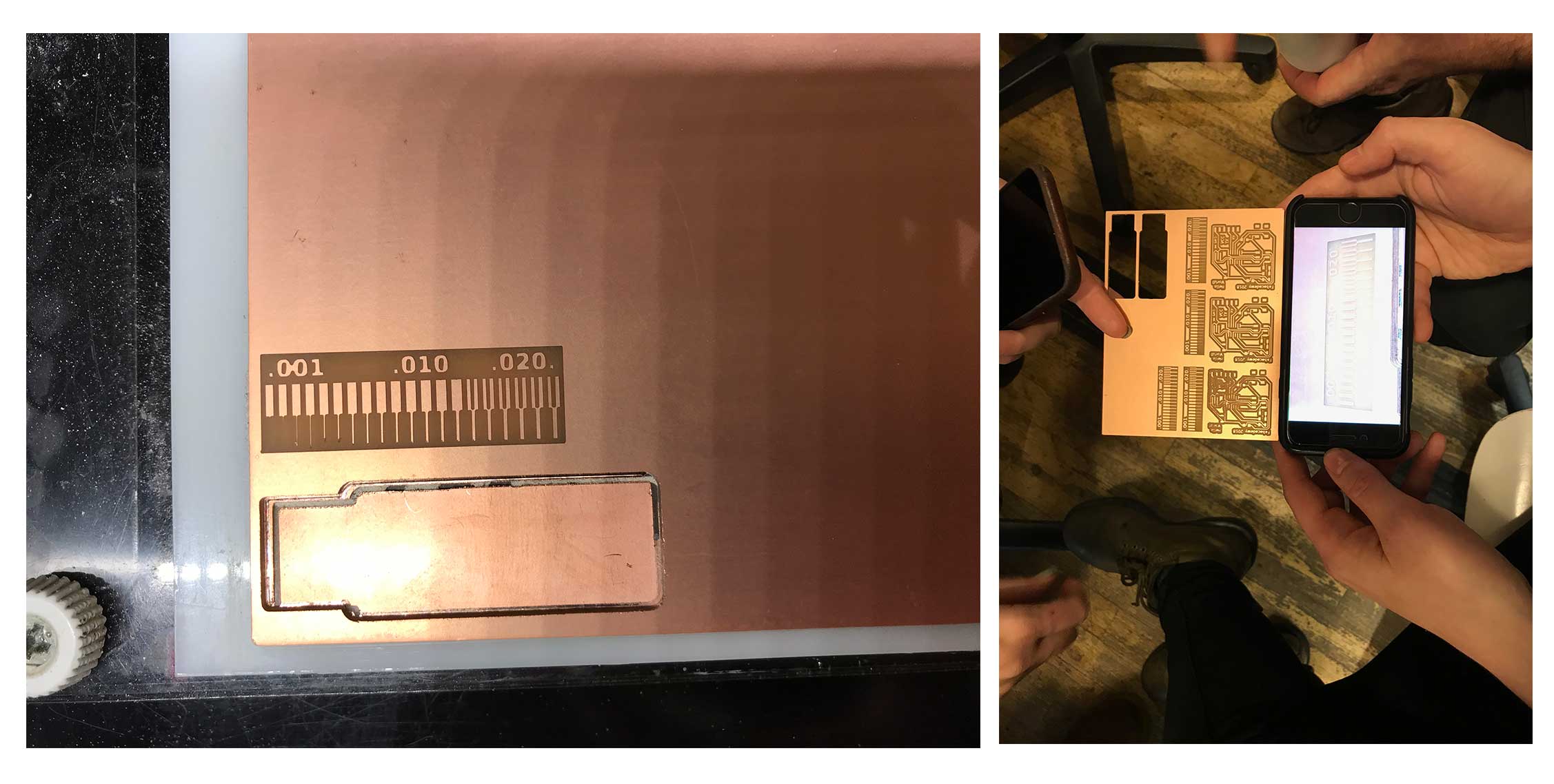
Step 4: the end result
When it was finished we compared the result to some previous test. In the beginning we thought it was less accurate, we had a discussion about it because we thought we did something wrong. However together with Henk we found out that the more accurate versions were made with one flute 0.4 mm mill while we used a two flute mill.
 Discussion about the end result of our group assignment
Step 5: make a cut out
We also wanted to make a cut out of our line test. While we set up the Modula with a new drill, 0.8 mm also two flutes, Anne made a cut document from the line test. She used the original file and removed all the lines. So we had a black square which was the cut out.
For this new file we changed the settings in Mods.
- First we selected the new file
- select mill outline as we want to cut trough the material
- We changed the tool diameter to 0.8 mm, and double checked the default settings
- We double checked the origin to make sure the setting are the same as our previous milling job, x: 15 and y: 27
- Establish a connection
- Calculate file > send file > it started to cut out our line test.
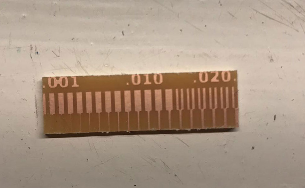 The end result of out line test
The cut worked but the outline was too tight. The picture shows parts of the lines and numbers were cut off. We checked what could have gone wrong. We realized we should have selected invert with choosing the cut outlines. Anne made a black rectangle but we only needed the outline of the rectangle.
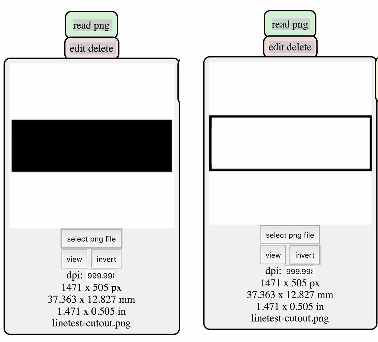 We should have chosen invert for the outline
What I did – step-by-step
Before this week I never used the PCB-machine before. I don’t have any experience with making and designing my own circuits. I did solder a electronic cricket once but that’s about it regarding my soldering skills and experience.
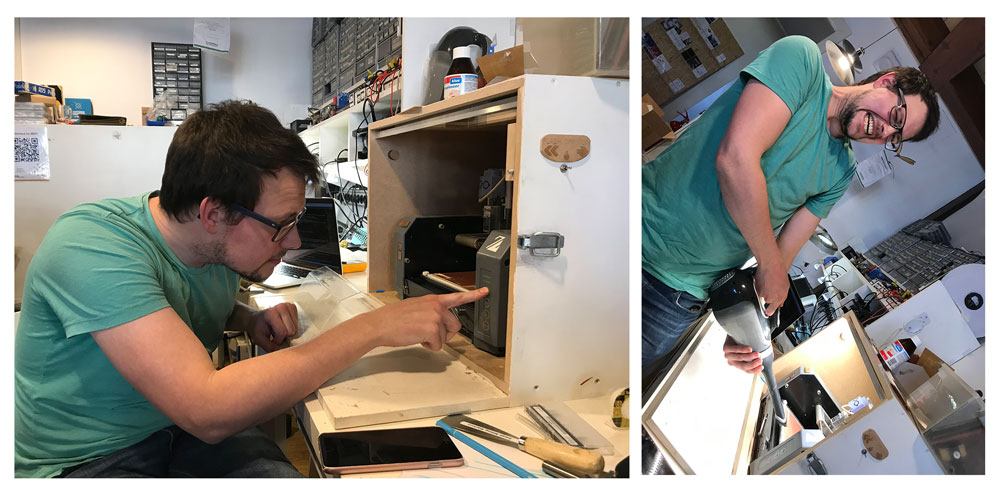
Step 1: preparing the PCB Machine
 Step 1: preparing the PCB machine
- Screw the sacrificial layer from the bottom and remove it from the machine
- Remove the copper plate with a paint scraper, best is to first peel off as much as possible.
- Clean the copper plates with sticker remover.
- Add double sided tape to the clean copper plate. Stick this plate to the sacrificial layer —> use force other wise the adhesion is not enough and the copper plate stays a bit bend which influences the end result.
- Place the sacrificial layer with the new copper plate back in the PCB machine, use the screws to make sure it’s tight.
- Change the mill: use the small hex key to untighten the mill on side of the nozzle to and hold it with your fingers so it doesn’t drop on the plate.
- Put a new mill in, check if it’s 0.4 mm, again be careful and use your fingers to hold the mill so it won’t drop.
- Place the mill back as high as possible, tighten it with the hex key on the side.
- Turn on the machine with the power on button.
Step 2: preparing the file with Mods
 Step 2: preparing the file with Mods
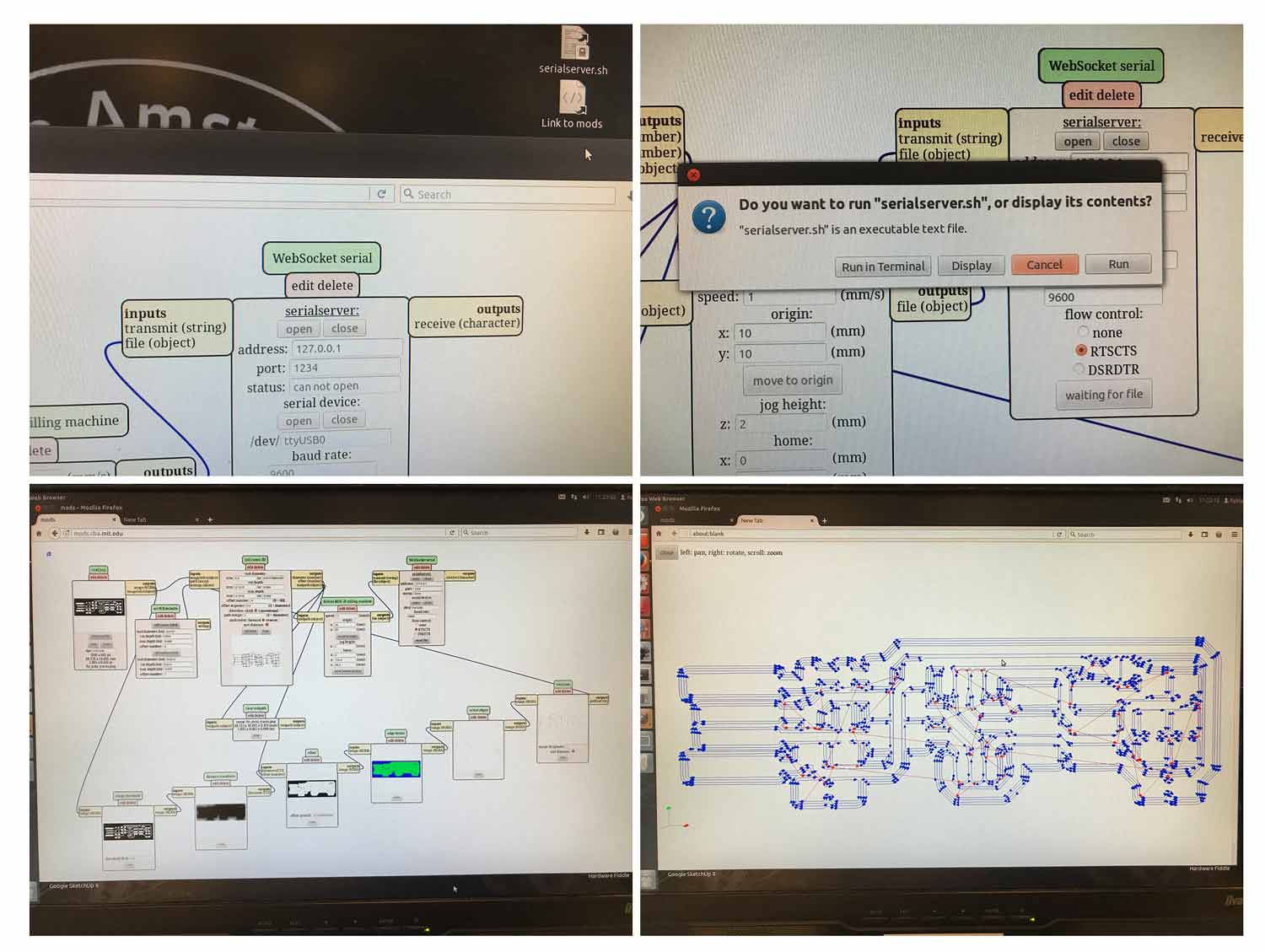
- Open Mods > right click > program > server program > Roland Mill MDX20 > PCB
- I can now see the modules that together generate the gcode and directly talk to the machine. I mainly use the upper part of the screen to the change settings the lower part shows how the files are sent to the PCB.
- Read PNG: open the png file of the FabTinyISP.
- Set PCB defaults select mill traces.
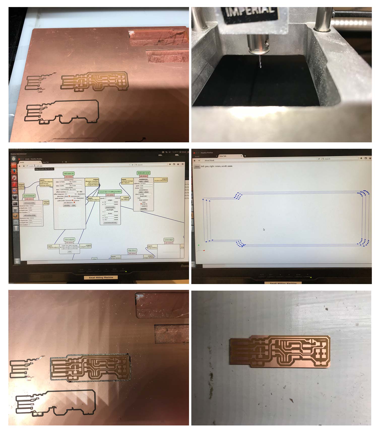
- Mill Raster 2D > set the tool diameter to 0.4 mm (double check if these settings are the same in the Set PCB default settings, otherwise manual change them)
- tool diameter: 0.4 mm
- It is possible to change the offset lines, these are the number of lines it will cut away outside of the traces. This is useful for soldering so you don’t have copper too close to each other. The default is 4 lines outside with half a line overlap. Settings I used are:
- Offset number: 4
- Offset stopover: 0.5
- Direction climb
- Path merge 1
- Path order: forward
- Sort distance
- Roland MDX 20 - Milling Machine > set the speed. It’s now on 2 mm/s which we used with the group assignment however Rutger and Heidi both broke a mill when they used this setting for their own assignment. So Henk advised to lower the speed. The settings I used are:
- Speed: 1 mm/s
- Origin: x: 16 / y:25
- Jog height 2 mm (the height it will use to travel so it won’t scratch the copper)
- Home: x: 0 / y: 152.4 / z:60.5
- WebSocket Serial > to be able to communicate with the machine you have to make a connection with a serial server. Go to desktop > double click the serialserver.sh > a pop-up opens > click run in terminal.
- Now it shows: client address 127.0.0.1 on server port 1234 > this establishes a connection between the computer and the machine which is needed to send my file
- Go back to Mods > in the web socket terminal it already shows the right address and port
- Go to serial device > open > status went to socket not open
- Go to serial server > click open > now the status is changed to serial port opened
- Press move to origin > now the machine moves and you know you have a connection.
- Double check the origin, my first one wasn’t correct because there were some other designs on the copper plate I used. So I had to change the y to 50
- new origin: x:16 / y: 50
- Change the z-axis: use the tools on the PCB machine, with the down button move the nozzle all the way down.
- Now unscrew the milling bit with the hex key and lower the height by placing it on the plate, carefully turn it to remove the dust and tighten it again. This is how you set the z-axis
- Now with the Tool up button just move the nozzle up a notch this way it has space to mill > I forgot that I had to do this before putting the drill on the plate so I do step 17 and 18 over again.
- Mods > go to Mill raster 2D module > click calculate > it opens a new tab with the file that will be send to the PCB Machine. The blue lines are the ones it will mill and the red lines shows how it will travel
- Go to WebSocket serial module > now I see it says send file when I press this it will send the file to the machine and the machine will start
- While it’s milling I can use the Tool View button on the machine to check if it’s milling correctly.
Step 3: cutting out the FabTinyISP
 Step 3: cutting out the FabTinyISP
- To cut out the FabTinyISP I first need to change the milling bit to a 0.8 mm drill.
- Turn off the machine for safety
- Unscrew the milling bit with the hex key on the side, be careful hold it and replace it with the new 0.8 mm milling bit.
- Go to Mods > select new file fes mini cut
- Select in Set PCB defaults > mill outline > tool diameter 0.8 is a default setting. Double check this and double check the settings of the origin. This should be the same as the traces.
- Establish the connection again with the serial server > this was lost because I turned off the machine.
- Set the z-axis: this time I need more space because this time we drill through the plate, so I moved the drill up a notch.
- When this is set lower the milling bit to the plate and tighten it again.
- Go to Mods > calculate
- Double check settings > I realized my speed is still at 1 mm/s > change this to 4 mm/s. This milling bit is thicker so I can use a faster speed.
- Calculate again and send file, the machine starts milling.
- Result: nice cut out!!!
- Clean the board with water and soap before I start soldering.
Step 4: soldering the components
 Step 4: soldering the FabTinyISP
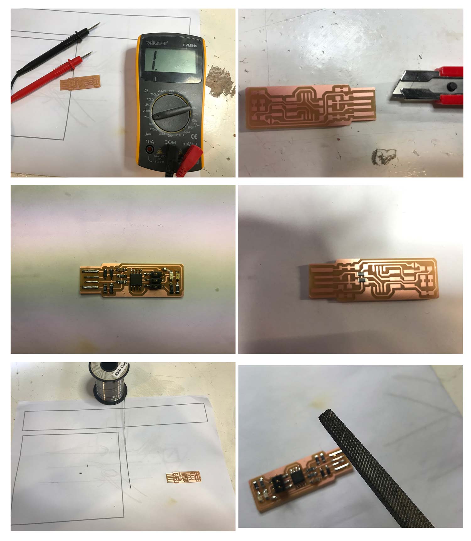
- Before I started soldering I checked for shorts. I first looked at my board to see if there were any copper pieces connected that didn’t match the original design. Secondly I used a multimeter and checked for shorts. I used this tutorial how to use a multimeter by makezine , second use a multimeter. to get a better understanding of the multimeter.
- To be sure there won’t be a short I removed all the small left over copper pieces from the board.
- I set the soldering iron on 70 % and used small tip to solder. A steady green LED means its warming up, and a blinking LED means that the soldering iron is on temperature.
- Things to keep in mind from Neils lecture before starting to solder “Start small to big, inside to out”.
- Start with a clean tip > put some tin on the tip and clean it with a sponge.
- I decided to start with the capacitor and resistor 3 and 4, because they are close to the ATtiny and small.
- First I put ‘glue’ on one side, this means I put some tin on the board where I want one side of leg of my component.
- After that I used the tweezer to place and hold the component on the right spot. With the soldering iron I heat the tin and I ‘glue’ the first part to the board.
- I go to the diagonal or opposite side of the component to solder this part. Hold the soldering iron close to the board and the component, this way I only need to add the tin and it nicely flows together.
- I follow these steps for each component. Slowly and steady to make sure it’s as neat as possible.
- For each component I can check how to place it on the board because it shows a line or a dot, which corresponds with the design. However for the LEDs I first couldn’t find which way was which. So I used the multimeter to find out. The ground is on the side with the green line.
- Step by step I soldered all the the other parts and legs of components on the board.
- I used thicker tin to solder the usb connectors and J1 in the design.
- When I was finished I first checked my design visualy by looking carefully to see if part are joined together with solder. This was luckily not the case. After that I double checked with the multimeter to find out if I have shorts. Everything looks good.
- As a final check I compared the components on the board with the list from the tutorial. This matches so I’m happy with the end result!
All the components used:
- 1x ATtiny45
- 2x 1kΩ resistors
- 2x 499Ω resistors
- 2x 49Ω resistors
- 2x 3.3v zener diodes
- 1x red LED
- 1x green LED
- 1x 100nF capacitor
- 1x 2x3 pin header
Step 5: installing the programmer
- First I need a driver, I use MacOs thus I needed Crosspack which I downloaded from their site.
- I downloaded the firmware zipfile from Fab Academy site and extracted the file.
- I followed the steps mentioned in the tutorial > open terminal > go to folder of firmware > command
make> this created the hex file - I use the usbtiny so I don’t have to change parts in the make file.
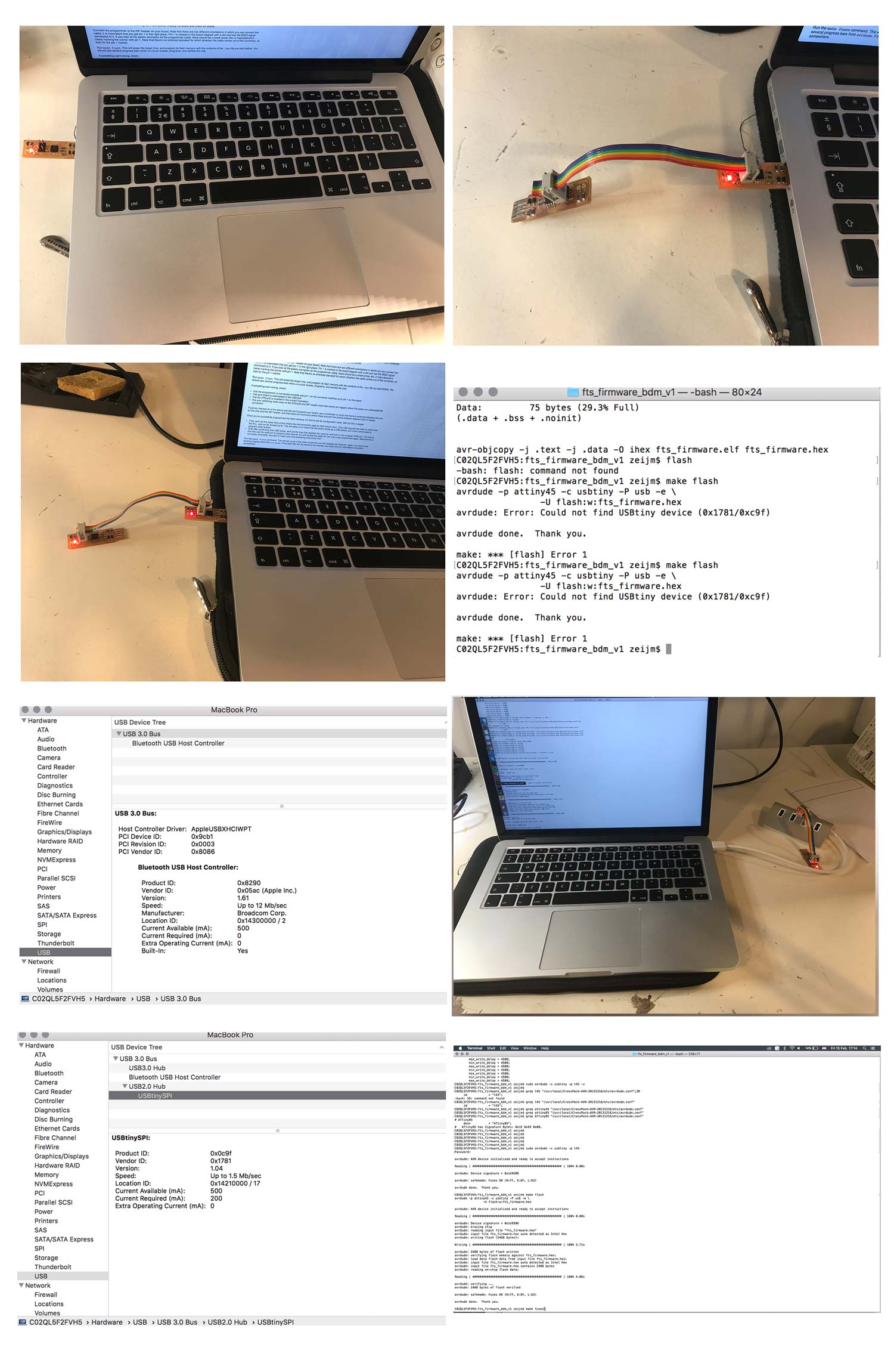
- Plug in USB - the red light on the board turns on
- Now add the programmer > first I did this the wrong way around. I had my own USB first followed by the programmer. This didn’t work so I turned it around the right way. First the programmer followed by my own usbtiny.
- I run
make flash, did gave th error message:*avrdude: Error: Could not find USBtiny device (0x1781/0xc9f) - This error took a while to debug. More details about this part can be found in the next section.
- We troubleshooted and in the end we found that my laptop only has a USB 3 port, while the installation of the firmware only works with USB2. So we used a USB2-hub. 10.
- I typed
make flashin the terminal > and it worked! make fuses> this worked as well! FUSES OK
 Step 5 and 6: installing the programmer and testing the usb
Step 6: testing the usb
- First unplug usb and disconnect the programmer.
- Plug your usbtiny back in the USB
- Open Apple system Profiler > USB > check if shows usbtiny, it’s there!
- After this check use the command:
make rstdisbl - I get an error:
avrdude: initialization failed, rc=-1 Double check connections and try again, or use -F to override this check. - I had to read more carefully. The tutorial mentions: “use the programmer”, I forgot this part. So I tried again with the programmer > run
make rstdisbl> and it worked > Fuses OK - Last step is t remove the solder bulb > this was more of a hassle than I thought > I used the blue pen > first it didn’t work and it was messy. But I found out it needed to be warm to work. So I heated up the tin and immediately put the pen on top of it to suck it from the board. This way worked very well.
What I did wrong – and how I solved it
During the process of developing my own FabTinyISP I had two main problems. The first problem was when I first started milling on the Modula, which was easy to fix. The second more frustrating problem was installing the firmware on my FabTinyISP.
The mill didn’t drill deep enough
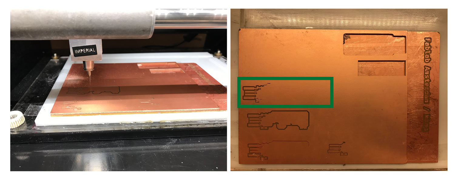 Milling drill didn’t cut through, see inside green rectangle
With my first time milling the drill didn’t mill deep enough on some parts. Other parts were fine so properly the plate isn’t straight or the plate is not glued straight enough on the sacrificial layer. So I stopped the machine and started over with a different origin. I will start more in the middle as the plate seems more level.
How to stop and restart the machine
- Press cancel on Mods
- Press both Up and Down for 10 secs on the PCB machine
- To move the plate to the middle I changed the origin to x: 40 and y: 50
- From here I follow the same steps as before. I reset the z-axis with the hex key.
- Press calculate and send file
- This time it worked
Make sure to check the plate if it’s straight and make sure to put double sided tape evenly on the plate as small changes can influence the outcome.
Error: Could not find USBtiny device
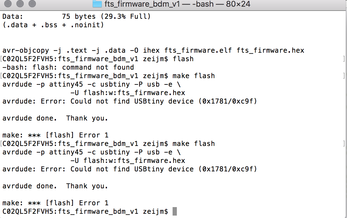 Error message: could not find usbtiny device
This error took a while to debug. First I checked my board again to see if I didn’t forget something. But this all looked good, and Henk tested my board on his computer. On his computer it work fine so I had to check something else. Joey got the same error when he was installing his usbtiny.
Previous Fab Academy students with the same error.
So I looked into the Fab Academy archive to see if other students had the same problem.
Student Ramiro Ordonez forgot to plug-in his programmer. At my first try I had the programmer and my own tinyusb the wrong way around. That was not the case this time and I double checked if it was plugged-in right, it showed a Red LED on my board so this wasn’t the case.
Jie Qi forgot to install the driver. First I thought this must be the problem. That I did something wrong with installing the driver. So I double checked this and in the end I installed the driver twice. However I still had the same problem. So the driver wasn’t the problem.
Xin Wen mentions that: “A way to check if the error comes from your board or the programmer is to probe the clock signal on the programmer when the programmer is trying to program and if there’s no clock signal, it’s probably because the programmer is not working”. We double checked with the laptop of Henk if the programmer was working and he also checked if my board was working or not. Both were working fine on his laptop.
Eikka Antikainen solution was to take another board, something I didn’t want to do. I want my own FabTinyISP to work.
These advises helped but in the end it didn’t give me the solution.
Help from Henk
Henk helped me to find the reason for this error message. He tried a lot of options but also still got the same error message that the usbtiny cannot be found. While Henk was trouble shooting I reread the tutorial and we both realized that the USB-port might be the source of all troubles. I checked the essentials of my laptop. It mentions that my USB-port should be able to read USB2, however we checked the Apple System Profiler and it didn’t show up.
- USB check from Fab Academy tutorial: “Open Apple System Profiler (Apple Menu → About this Mac → More Information; or from the Utilities folder). Select USB from the list on the left, and you should see the USBTiny listed as a device on the right. If it shows up, it is working properly”.
We used an USB2-hub to see if this would help. But I still got the same error message and the USB-hub didn’t how up in the system profiler. We checked if the USB-hub worked with Henk’s computer and it did. So to be sure we plugged the hub in my other USB-port and this worked! It showed in the system profiler and it showed the usbtiny. After this it was easy to follow all the steps of the tutorial.
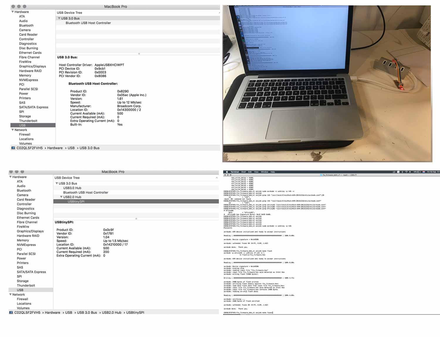 The USBhub is the solution to the error message
What I learned
Soldering environment matters
Soldering is very precise work. So best is to keep my soldering environment as clean as possible. It really works for me to take one component at a time. This provides a clear overview and no mess or mix-ups.
Soldering needs practice to get it smooth and shiny. In beginning I used magnifying lens with light but in the end I preferred to solder without magnification. But the light is really important with such small pieces.
Patience
Not only soldering takes patience and calm, debugging as well. It was frustrating that I was almost done and was stuck with the error message. However it’s important to ‘keep calm and carry on’ debugging. Best thing to do is take it step-by-step and always double check what you’ve done.
What made me proud!
I really liked the soldering part and I’m proud that it looks neat with not too many blobs and it works.
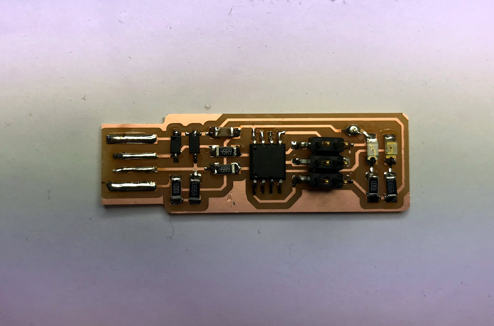 Happy soldering
Credits and references
This week I got help from Henk while debuggiung the error message with my FabTinyISP.