4. Computer controlled cutting
This week we have a group assignment to characterize our laser cutter, making test part(s) that vary cutting settings and dimensions and to define the kerf of the laser. The individual assignment is to cut something on the vinyl cutter and to design, laser cut, and document a parametric press-fit construction kit, accounting for the laser cutter kerf, which can be assembled in multiple ways.
Files, planning and tools
Files
- Illustrator file group assignment
- Fushion 360 file includes design 1, 2 and 3
- Illustrator file vinyl cutter - leaf nerves
Planning
- get instruction on the laser cutter on vinyl cutter of the Waag Fab lab
- as a group define the kerf of our laser cutter
- document our process
- create a parametric design for the press fit construction kit
- combine this design with the vinyl cutter assignment
Tools
- Illustrator
- Fushion 360
- Knife and scissors
- VinylCutter Roland GX-24
- Lasercutter BRM1612
- Software: Lasercut 5.3
Link with final project
For this weeks assignment I want to work on the concept of modularity. In addition I want to experiment with shape and form, and I want to get a better understanding of each part of the tree starting with the leaf. Therefore I gave myself constrains related to my final project for the design of the press-fit construction kit.
- design one piece that can be used to construct more complex shapes.
- this piece should have a leaf-like shape
- I want to build a tree with this leaf.
Research and inspiration
As I don’t have a technical or a architectural or construction background I searched for inspiration from similar ideas in previous years or from designers.
Modular construction unit
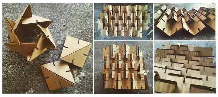
Because I set myself the constrain of creating one leaf to build a tree, I first researched modular construction kits and I found three very inspiring examples.
 Modular construction kit (by Vaishnavi Ramesh)
This construction kit made by Vaishnavi Ramesh a graduate student of Architecture at the Rhodes Island School of Design, is really inspiring. Because she uses basic shape(s) as building blocks, she shows different placement of joints, and best of all she uses the fold of the cardboard for stability and flexibility. I would like to use this as well.
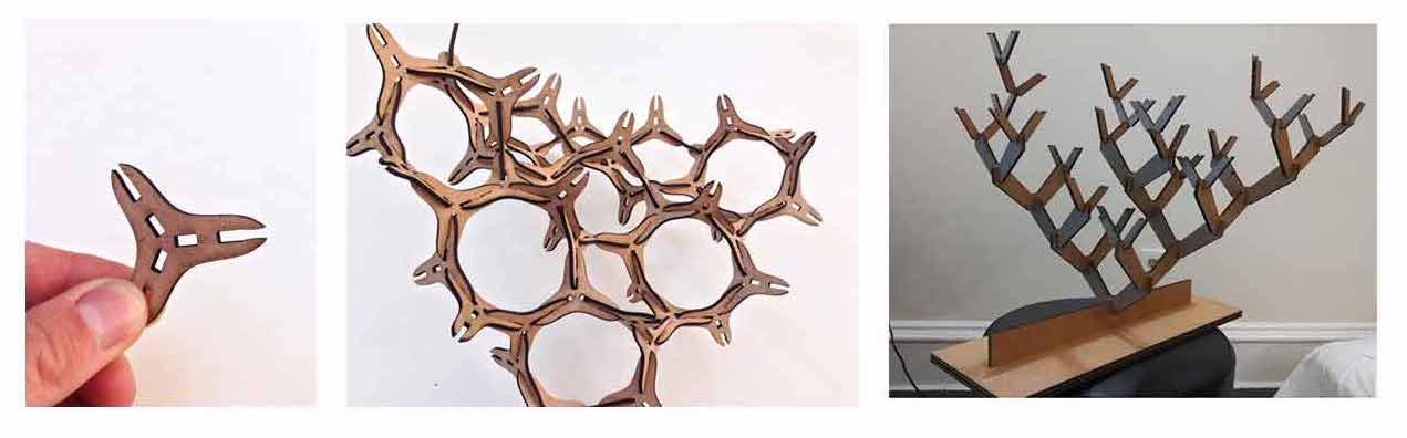 Modular construction kit by Henry Skupniewicz and a fractal tree by Nazmus Saquib
Two other projects that inspired me a lot, where from previous years of the Fab Academy. They’re both from the class of 2014. first one is by student Henry Skupniewicz. He created a very simple one piece modular press-fit construction kit, which really like. I want to use the same basic principles. Similar is the project by Nazmus Saquib, who uses two shapes, to create a fractal tree. This last one really fits my idea. However I want my piece to be more leaf-shaped.
Other useful inspirational links
These links are inspiration for possible experiments with placement of joints and flexures.
- Leaf like shape making use of a living hinge for fold by Joseluis Reateguischrader Fab Academy student in 2018
- Interesting placement of joints by Bara Vidarsdottir
- Flexure inspiration by Sands Fish
Research into parametric design
After my first design I realized it wasn’t parametric at all and I had no clue how to make a leaf parametric. I found two interesting research papers.
- A Parametric Active Polygon for Leaf Segmentation and Shape Estimation by Guillaume Cerutti, Laure Tougne, Antoine Vacavant, and Didier Coquin
- Disney Research paper: Editable Parametric Dense Foliage from 3D CaptureGaurav Chaurasia and Paul Beardsley. I used the Disney Research as basic idea for my design 2 and 3.
- This is a useful tutorial on control point splines in Fushion 360. I needed this to make my leaf parametricTutorial control point splines Fushion 360
What we did – group assignment step-by-step
First we got instructions on how to use the laser cutter and the vinyl cutter. I do have experience with using both machines. The laser cutter at the Waag Fablab is however different version from BRM than I am used to at the Makerslab. The one at the Waag is a BRM1612, size 1200 by 1600 mm and it used the Lasercut 5.3 software. It The Vinyl cutter is the same however the use of the plug-in in illustrator is slightly different.
How to use the laser cutter and finding the kerf
Step 1: laser cutter software Lasercut 5.3
- save (illustrator) file as dxf (or as illustrator CS2) on usb
- open usb on the Fab lab computer, save the file you need in your own folder on the desktop
- open the laser program
- file > import > your file
- select the lines and give them a different color depending on what you want to do
- on the top right it shows all the colors, with each color you can tell the laser what to do
- for each color set if you want to cut or engrave
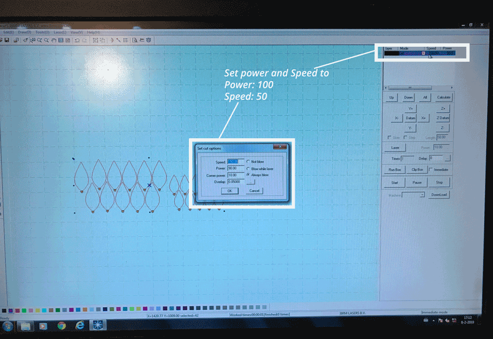
- for each color set the speed and power. the speed is how fast the laser will go and the power how powerful the laser will be. This differs per material. It good to test this before you start.
- make sure everything is set on output
- check the size of your design, dxf sometimes does something weird with sizes
- when you set every the dimension the way you want, press download
- a pop-up opens and press delete all
- after that press download
- now the file is send to the laser
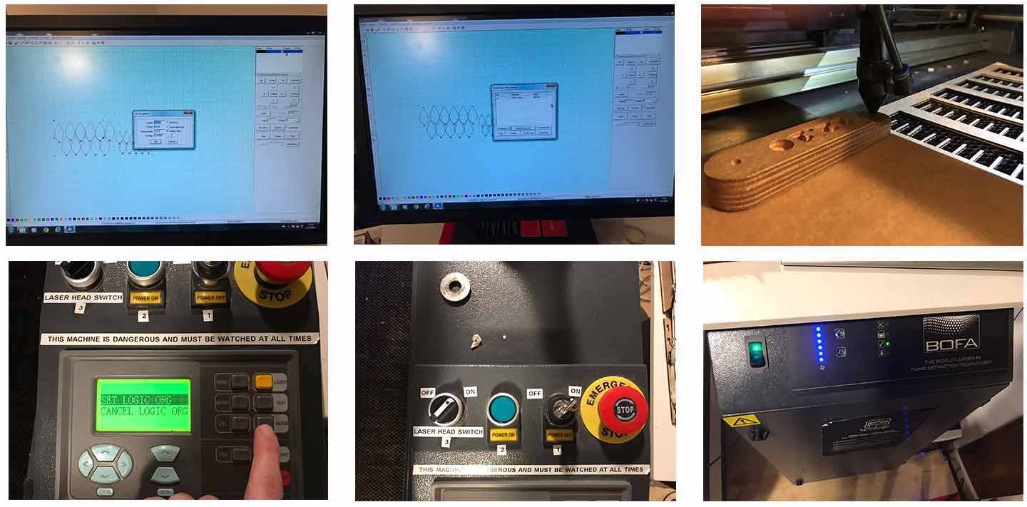 steps on how to use the laser cutter
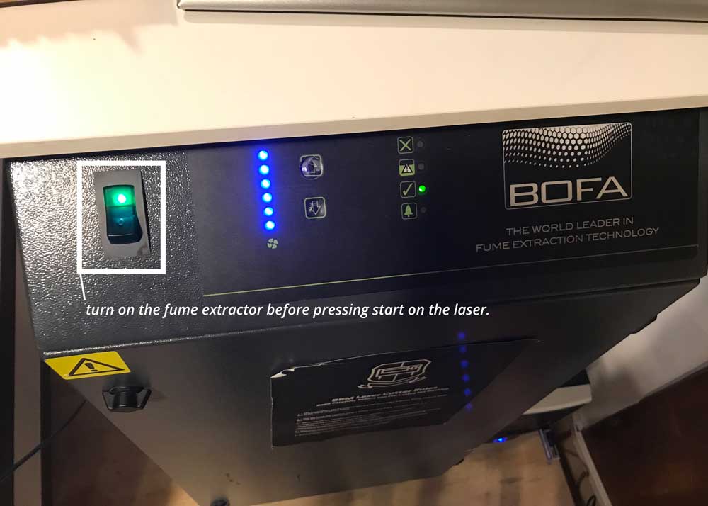 Turn on the fume extractor before starting the laser
 Turn on the fume extractor before starting the laser
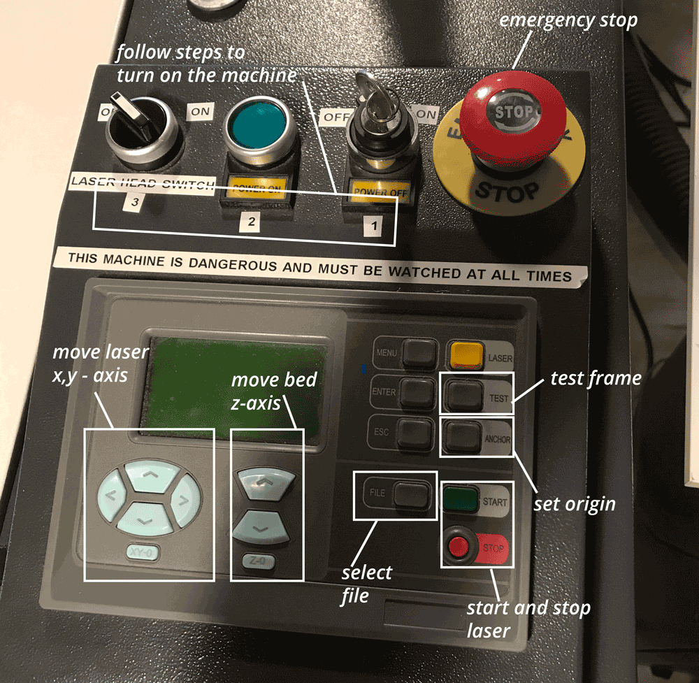 How the interface of the laser cutter works
Step 2: the laser cutter
- press file > you see your file > press enter
- press anchor to set the origin point of the laser
- if it’s not on the right place yet? you can move the laser with the arrows, you can use this to move the start point of the laser to the right place. After that press anchor
- test > shows you the frame of what you want to cut, this helps you to test if the file fits on your material
- laser > this gives a small laser dot, this is useful to line out your document
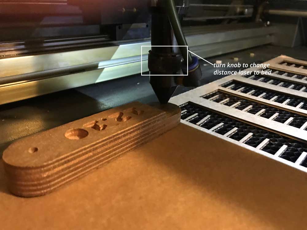
- set the focus point of the laser, you can use the wooden cube for this. Put it in between the laser and the bed. Move it till it fits under it with a little bit of resistance, not too much. You can move the bed to set the focus point with the arrows up and down. And you can loosen the laser untighten the screw.
Finding out the kerf of the laser
For this assignment I worked together with Rutger and Joey. We first made the illustrator file with blocks to be able to finally measure the kerf. I made a file in Illustrator and Rutger one in Inktscape. Because Rutger is most experience with the laser at the Waag he helped Joey and me with the basic to set everything correct.
Step 1: making the document in Illustrator
Rutger and I both created an document for the test. Rutger in Inktscape and I in illustrator. We had discussions about creating a grid and double lines in our documents. We both made a design with 10 blocks each 10 mm wide so 100 mm in total. Step I took to create the file:
- make file in Illustrator
- first select rectangle tool
- draw a rectangle
- make a grid out of it with: > object > path > create grid
- problem: this trick created double lines which are not useful when measuring the kerf.
- create a new drawing with the line tool
- draw one line and use copy-paste to multiply it
- use the alignment tool to align them.
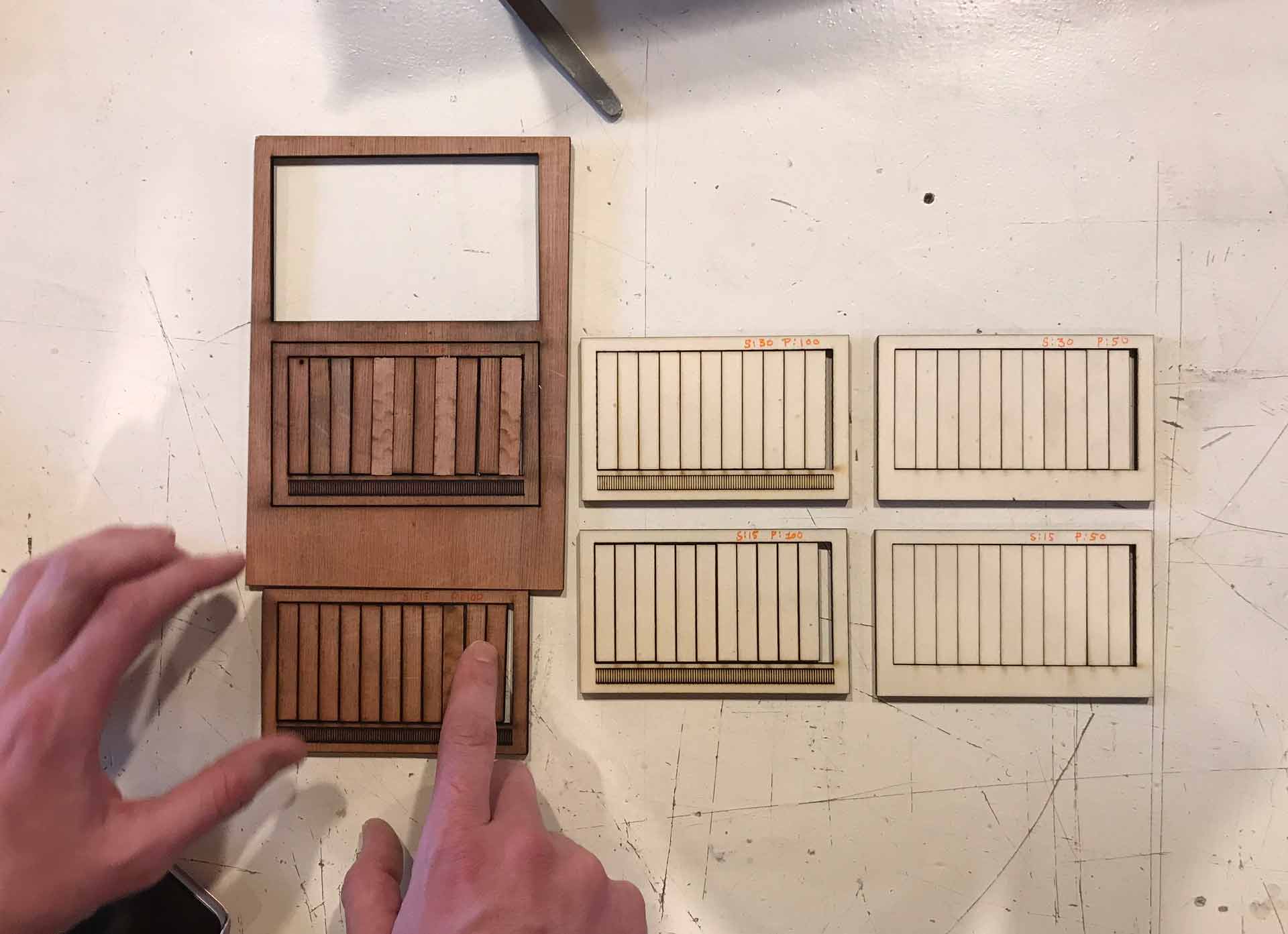 Results of the kerf test
Step 2: using the laser with different dimensions
Rutger assisted and explained Joey and I so we could practice with the laser, as Rutger has the most experience with the laser at the Waag. We decided to do 6 tests, where we changed power and speed to find out if the Kerf depends on these differences. And we used 2 different materials hard and soft wood to see if this would make a difference as well.
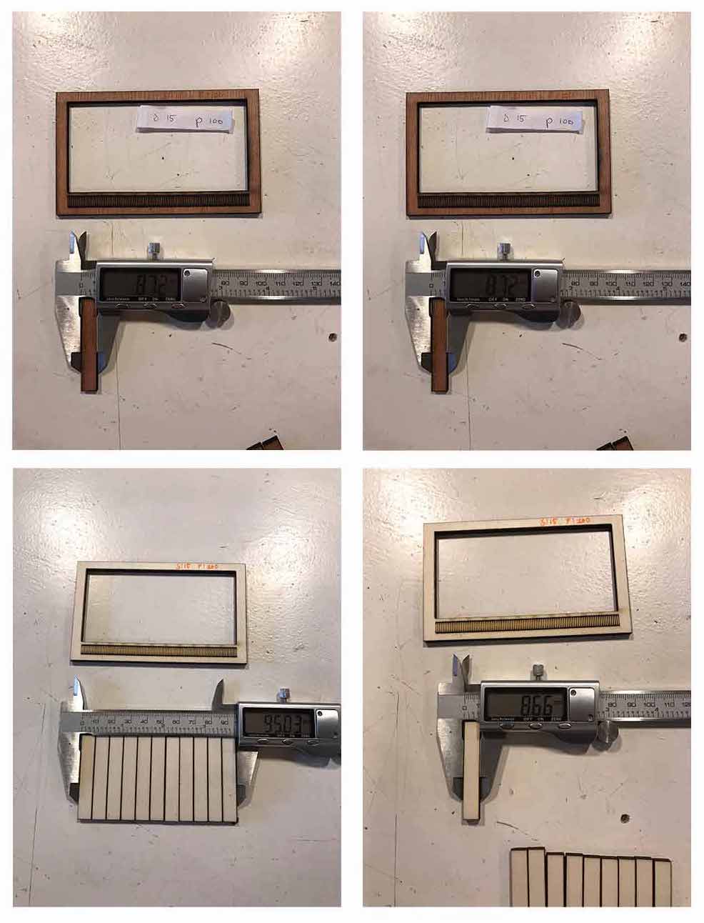 Measuring the results of the kerf test
Step 3: Measuring the kerf
Joey and I measured and documented the different distances for each block while Rutger wrote down the numbers and calculated the kerf with this calculation: (100-length measured)/11 = kerf, see image below. To use this curve you still need to divide the final number by 2 as the laser cuts in the middle of the line.
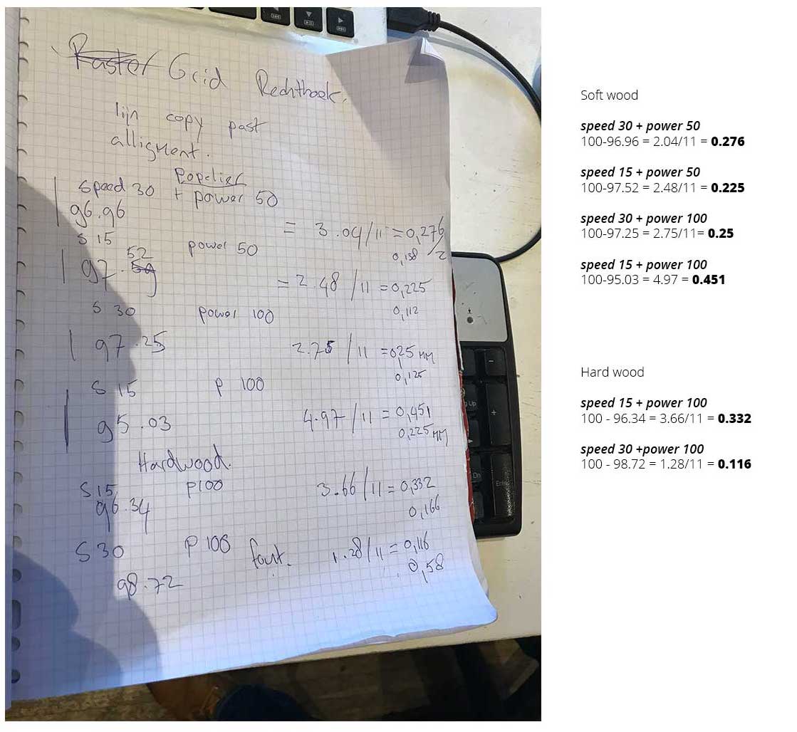 Calculations made by Rutger
We divided by 11 because somehow in the process of creating the illustrator file we ended up with 12 blocks in stead of 10. We needed to use 11 because the outside lines only count for halves.
There’s a difference in kerf depending on your settings, the smallest kerf was with the settings: speed 13 and power 50.
What I did – step-by-step
After we measured the kerf, I started with my design. I never made something parametric. It took me three designs to get the end result as I wished. First, I started in Fushion 360 as I would in illustrator by drawing the leaf. Second I used an article by Disney Research to create a parametric leaf, this one was too complex and hard to constrain. Finally I simplified this design to create the leaf with joints.
DESIGN 1: basic leaf shape inspired by Mondriaan
For my own experiment I wanted to use the basic leaf from Mondriaan’s abstract tree for my building blocks. So I started with drawing the leaf shape in Fushion 360
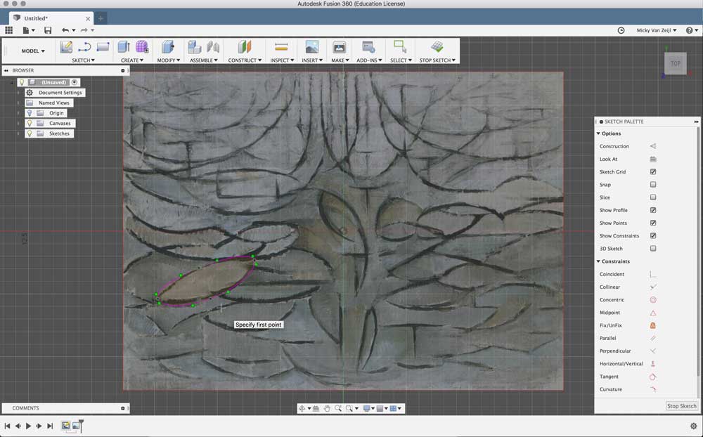 Drawing of leaf inspired by Piet Mondriaan
- Insert canvas > file > picture mMndriaan
- I used the spline tool to draw the shape
- After that I used the line-tool to create a joint
- Set constrains for the joint: the lines in the length should be parallel, and the width should be perpendicular with the length. I added this with the sketch palette
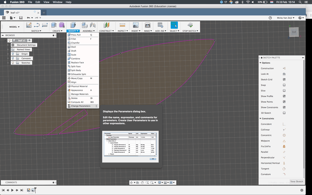
- Add parameters to the joint go to modify > change parameters
- Test how this would work to set the joint to length 25 mm
- Press enter > line is way to big.
- Change the parameter to 3 mm and this is better the line changes
- Now I realize that I don’t know how to do work with parameters using a spline
- And I realize that it with drawing it won’t work anyway because of the placement of spline-points.
- small line
 Step 4 as written above
 Step 6 as written above
 Step 10 as written above
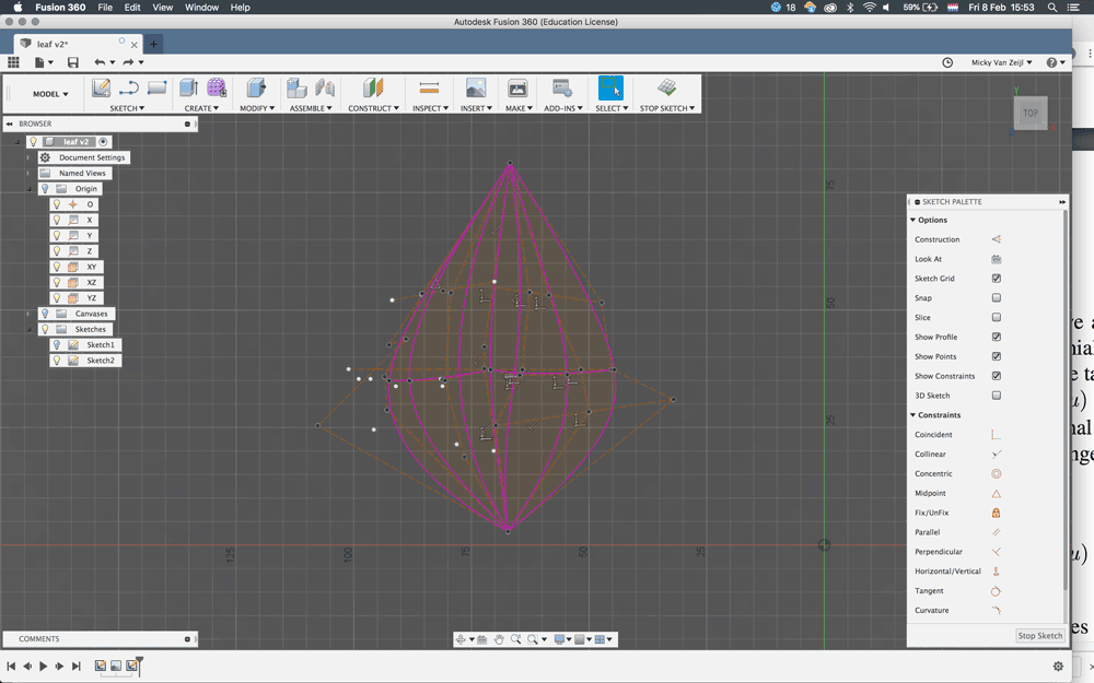
DESIGN 2: parametric design based on Disney research
I used the paper mentioned above by Disney research as new start point for a parametric leaf. However the paper was quite technical for me so I don’t get the formula’s but I understand by looking at the pictures what they mean. What gave me a good insight for the design for my leaf is that they identified three main features of leaf geometry:
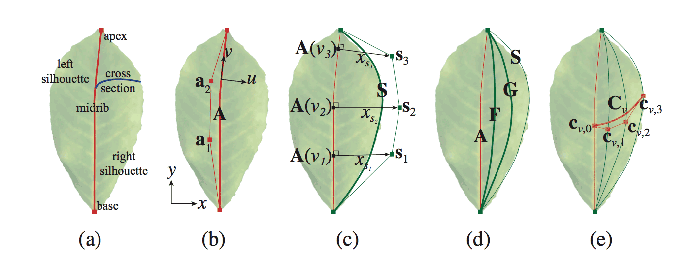 “We identify three defining features of leaf geometry: midrib, left/right silhouette and cross-section or the curve that connects points on the midrib to silhouette” (Beardsley & Chaurasia, 2017)
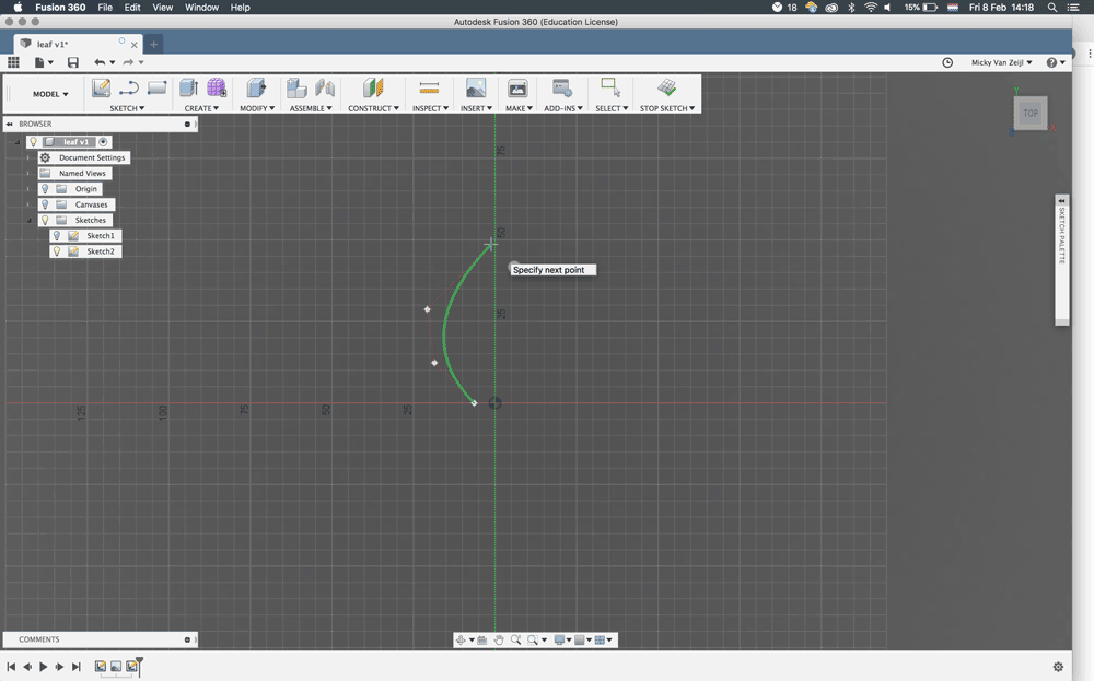
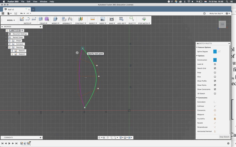
- In the paper they’re talking about Bézier curves. I researched this and in Fushion 360 I found that you can use control point splines for this. They have a good tutorial for this.
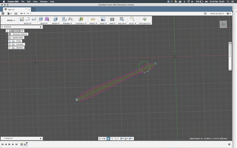
- I created the midrib or axis of the leaf with the control point splines, based on the image by above.
- I followed the steps they set under the image of the Disney research.
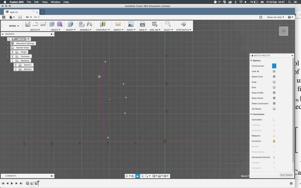
- Create three construction lines perpendicular to the point lines of the axis
- Use these for the control point spline of the silhouette
- Create two more lines in the middle of the silhouette, one at 1/3 and one at 2/3.
- Create a middle line, this is the curve that connects the midrib to the silhouette
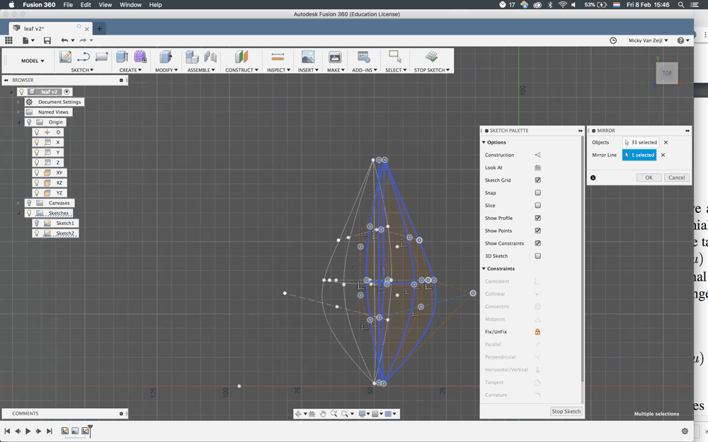
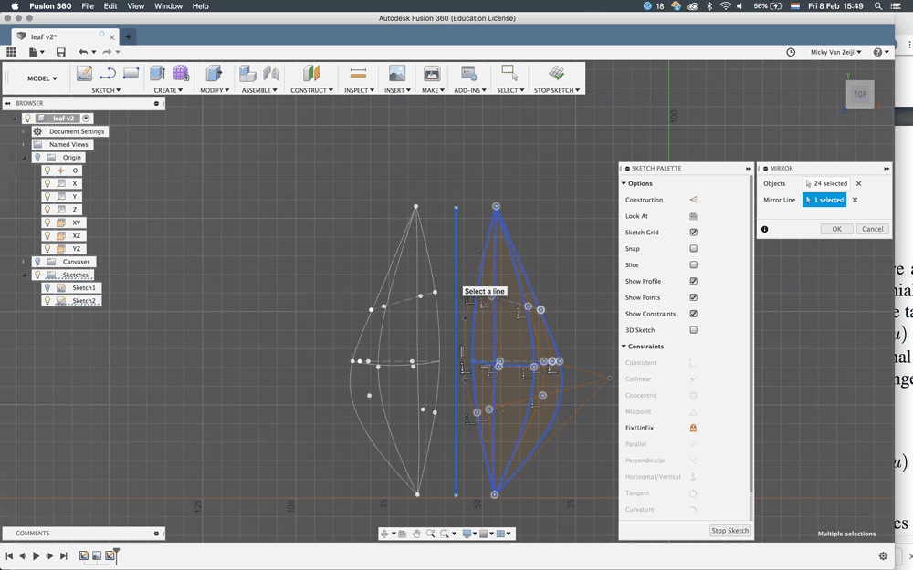
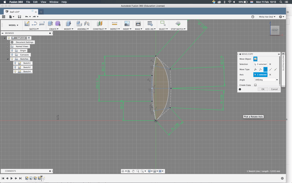
- Now the right part of the leaf is finish, next step is to mirror the line. However somehow this didn’t work. With help from Rutger who mentioned that a mirror can only work with a straight line.
- Draw a straight line, use a mirror.
- Now I have two silhouettes of my tree
- I connected them by joining the two top point together.
- Now I can change the shape of the leaf in a lot of different ways, which is really nice.
- However I still can’t change parameters, or at least I didn’t know how.
- I exported the outline to a DXF (right-click on the sketch save a DXF)
- I opened this in Illustrator to delete the construction lines.
- Save > send to the laser.
 Step 1
 Step 2
 Step 3
 Step 4
 Step 5
 Step 6
 Step 7
 Step 8
 Step 9
DESIGN 2: finding out the joints
I still didn’t know if I could create a tree based on this shape. Because I just wanted this leaf as my construction kit. so I laser cut it and first experimented with joins by just cutting and folding myself. This works better for me, I have to feel and see it, than calculating everything
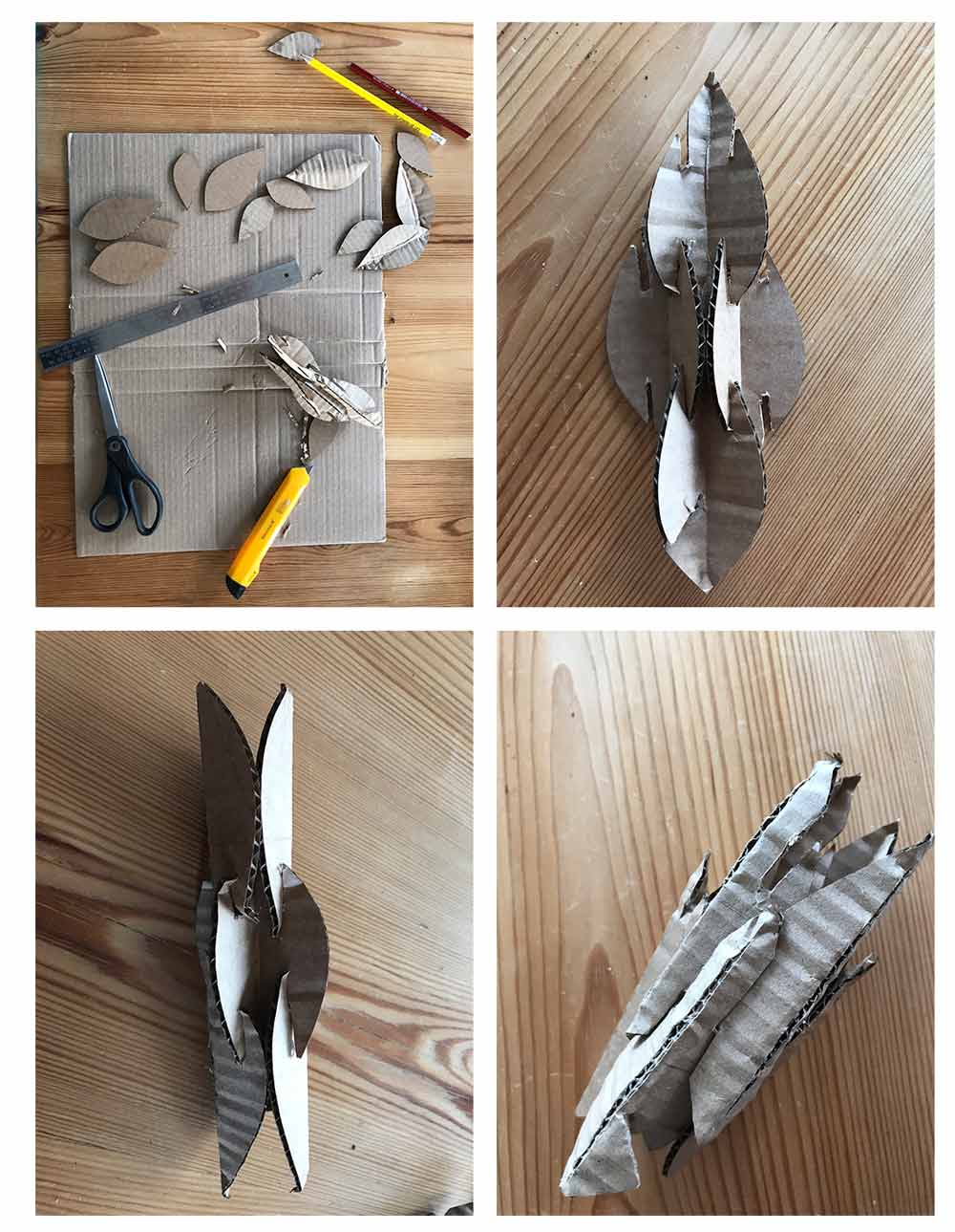 First I cut joints and folded the leaf to see if it would work
This gave good results and I saw that the idea of Vaishnavi Ramesh with a fold in the middle works really well. So I wanted to include this in my next design.
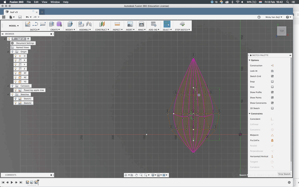
DESIGN 3: make it simple
I was really happy with my first attempt to recreate the Disney Research. However as far as I understand this design is made for 3D which made it really complex for me in 2D. I didn’t manage to make it contrained and parametric. So I started over and create a simple version and added joints. I followed the same steps as design 2, however with each step I tried to add parameters straight away.
 Step 1
 Step 2
 Step 3
 Step 4
 Step 5
 Step 6
 Step 7
 Step 8
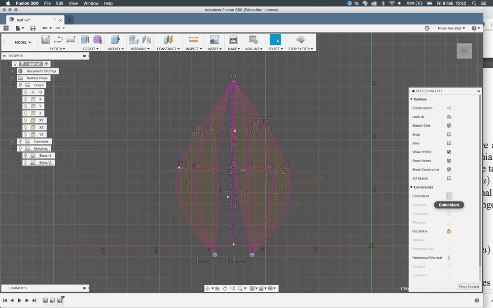
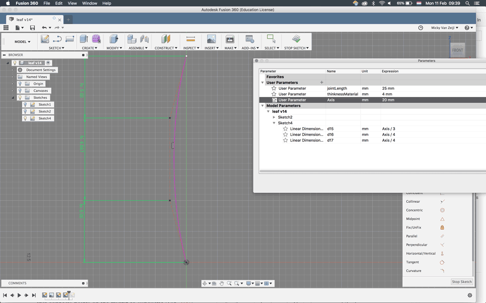
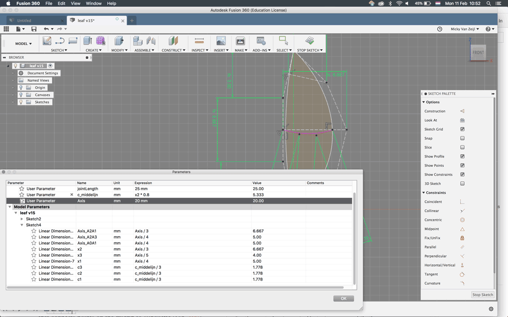
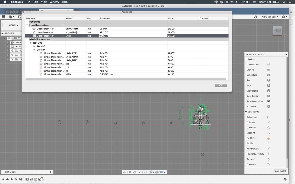
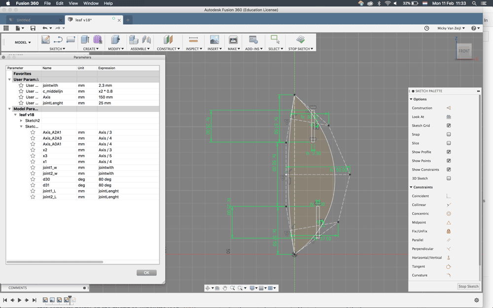
- First I created the axis with the control spline points.
- Press D (dimension) > I set the dimension for each part of the control spline, so I had three dimensions.
- I added the parameter Axis and set a size 100 mm
- For the middle part I added ‘Axis/3’ and the other ones ‘Axis/4’. Now I only have to change the size of the axis and the Midrib changes and keeps its shape.
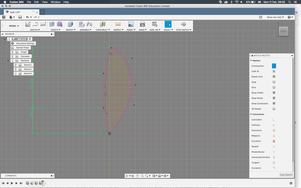
- After that I added the x-construction lines and set them perpendicular to the axis points.
- I added the silhouette outside line and added the dimensions relevant to the axis. First I didn’t do this and than the shape went crazy.
- I added a middle line, but I realized that this makes it more complex and it’s not necessary for the 2D shape.
- I mirrored the silhouette and now I have my basic leaf shape.
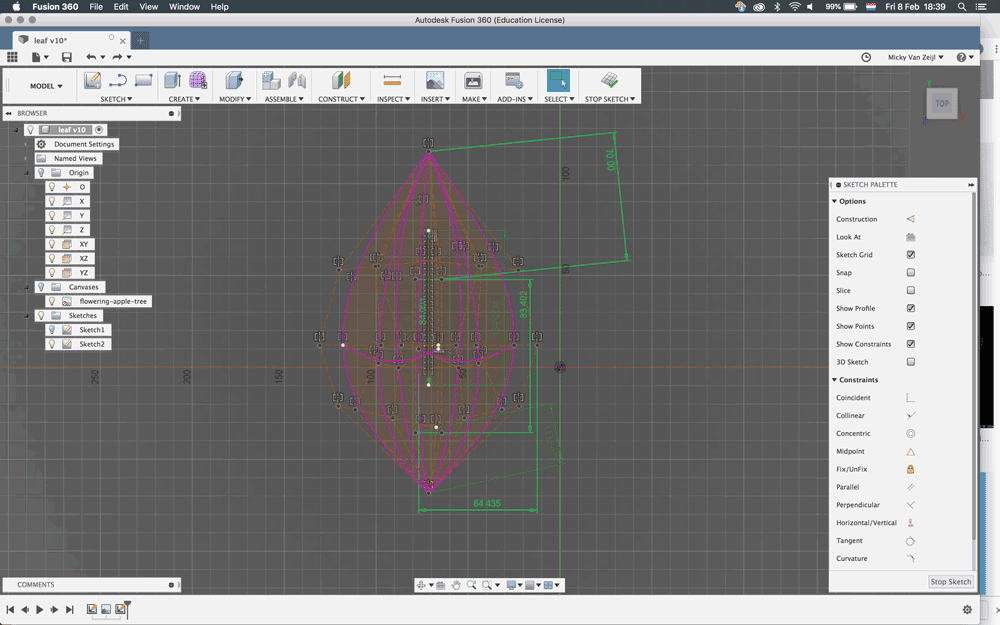
- More important is to add the joints.
 Step 1
Step 2
Step 3
Step 4
Step 5
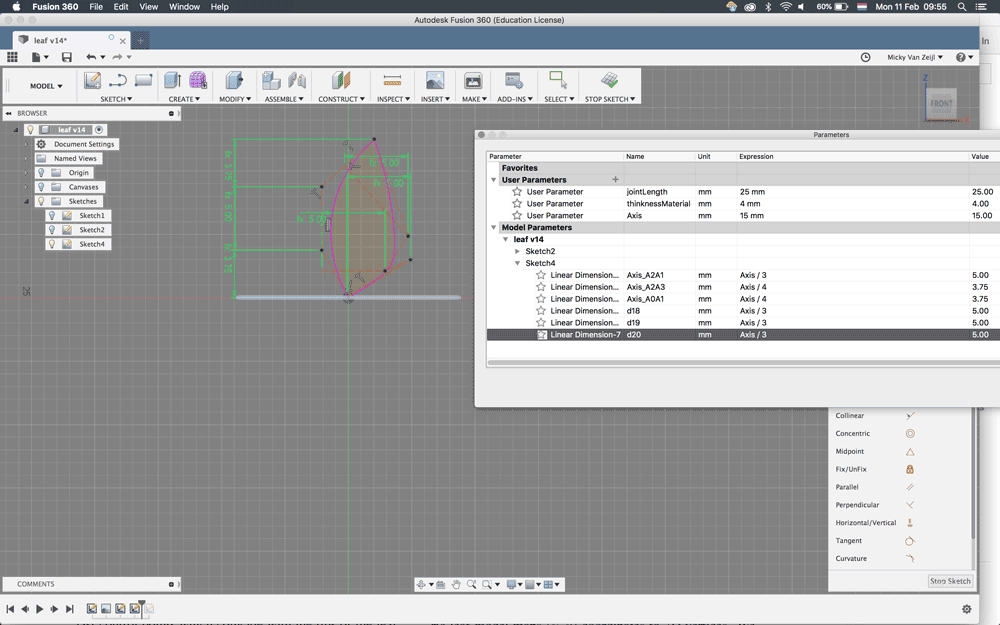
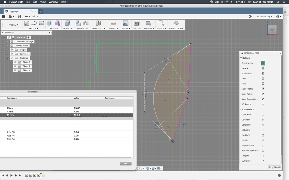
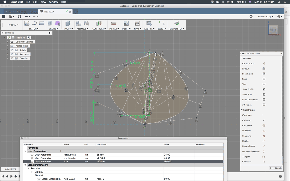
- I decided to make 2 shapes with different joints: the general one with joints on a 90 degree angle and a smaller one with an 45 degree angle. These will be more small decorative leaves.
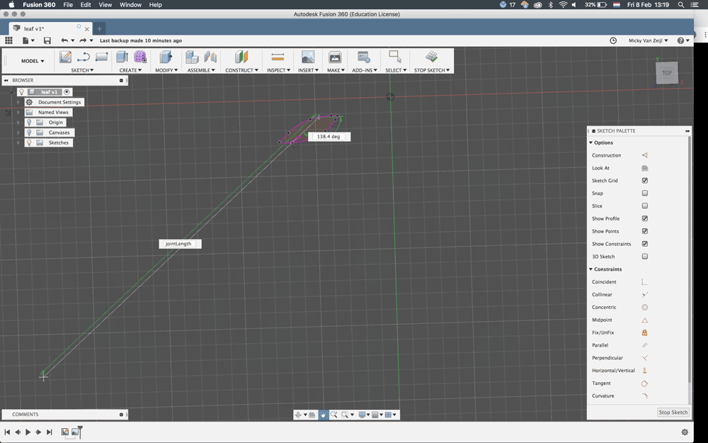
- This was a struggle because i wanted to be able to change the size of the leaf and to change the angle of the joints. But every time I would change the angle the whole leaf would change shape.
- I got some help from Connor an intern at the Waag Fab Lab. He showed me that: - I constrained my joints that they had to stay vertical. so I removed those constrains - Set one point as pivot point on the construction line, now with D set the degree - This worked but my joints went all over the place. I forgot to constrain them. So I set the length parallel and the width perpendicular to the length
- It works! I can set the length of the leaf and I can set the degree of the angle with parameters. However I can’t change the width if I use the degree.
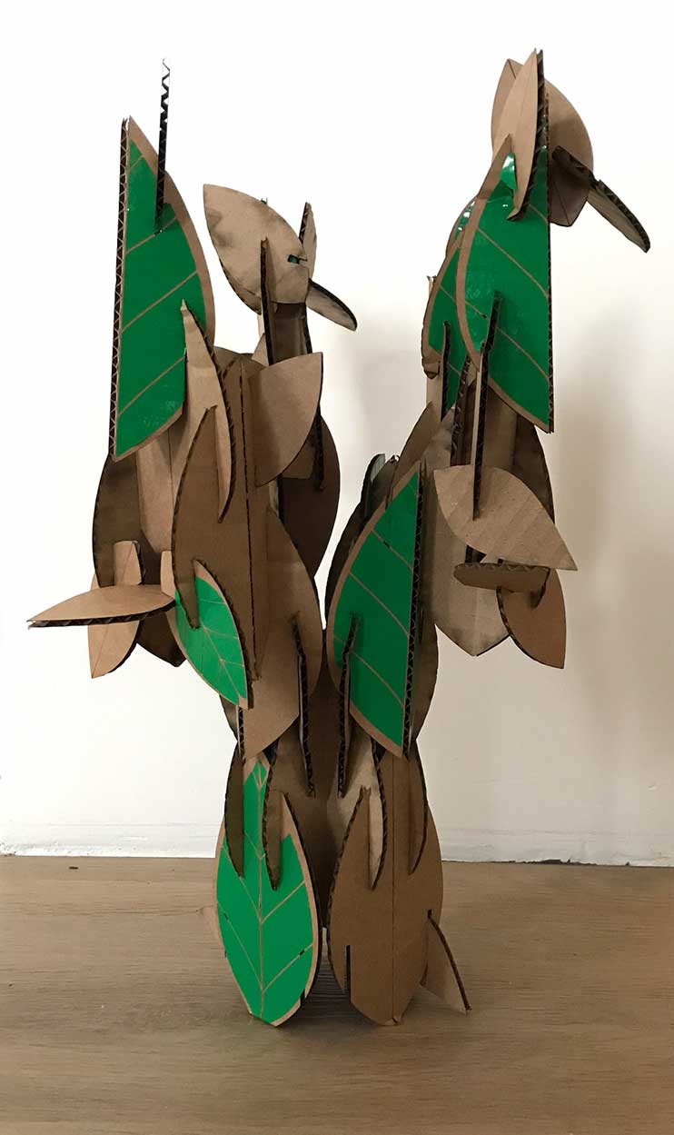
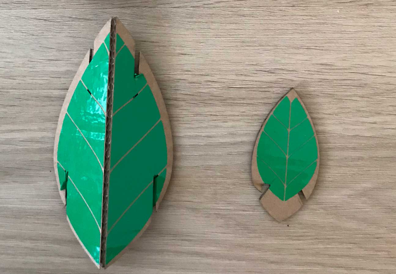
End result: 2 leaves to build a tree
In the end I created two leaves a bigger one which is the basic building block and a smaller one to add leaves to the tree. With the fold you can press-fit them in different ways and create a very strong construction.
 Setting up the Power and speed in the laser software
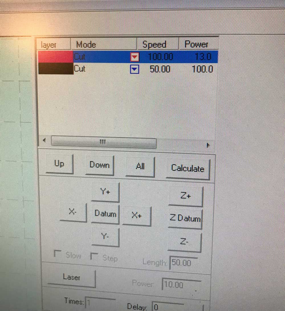 Setting up the Power and speed for kiss cut and normal cut
Settings laser cutter:
- Cut: Speed 50 / Power 100
- Kiss Cut: Speed 100 / Power 13
I used the kiss cut to create the middle line. I only 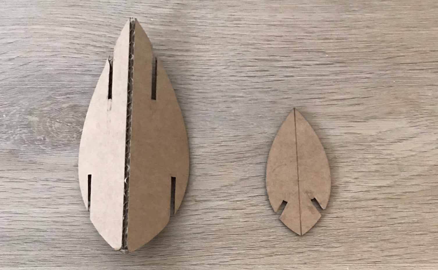 end result laser cutter leaves
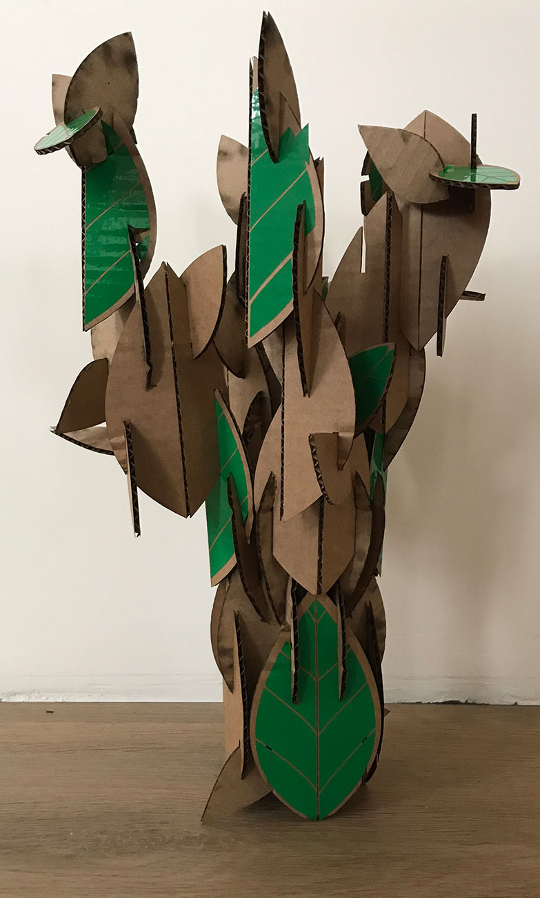 End result tree made from leaves
 Top view tree made from leaves
 End result press-fit construction kit: tree made from leaves
How the Vinyl cutter works
In the Makerlab at our University we have the same VinylCutter Roland GX-24 as the Waag Fab Lab, with an working area of 50 to 584 mm wide, so I already knew how to work with it. However the print function via Illustrator is different. I combined the assignment of the vinyl cutter with my design for the press-fit construction kit. I used the leaf shape to create nerves with vinyl. I was in a hurry therefore I made the stupid mistake and forgot to include the joints in the design of my nerves.
Steps I took in Illustrator:
- open DFX file of the laser cutter into illustrator
- Use pen tool to create nerves
- Object > path > outline stroke
- I used this to outline the stroke. First I thought of using both the strokes as the fill for my leaves.
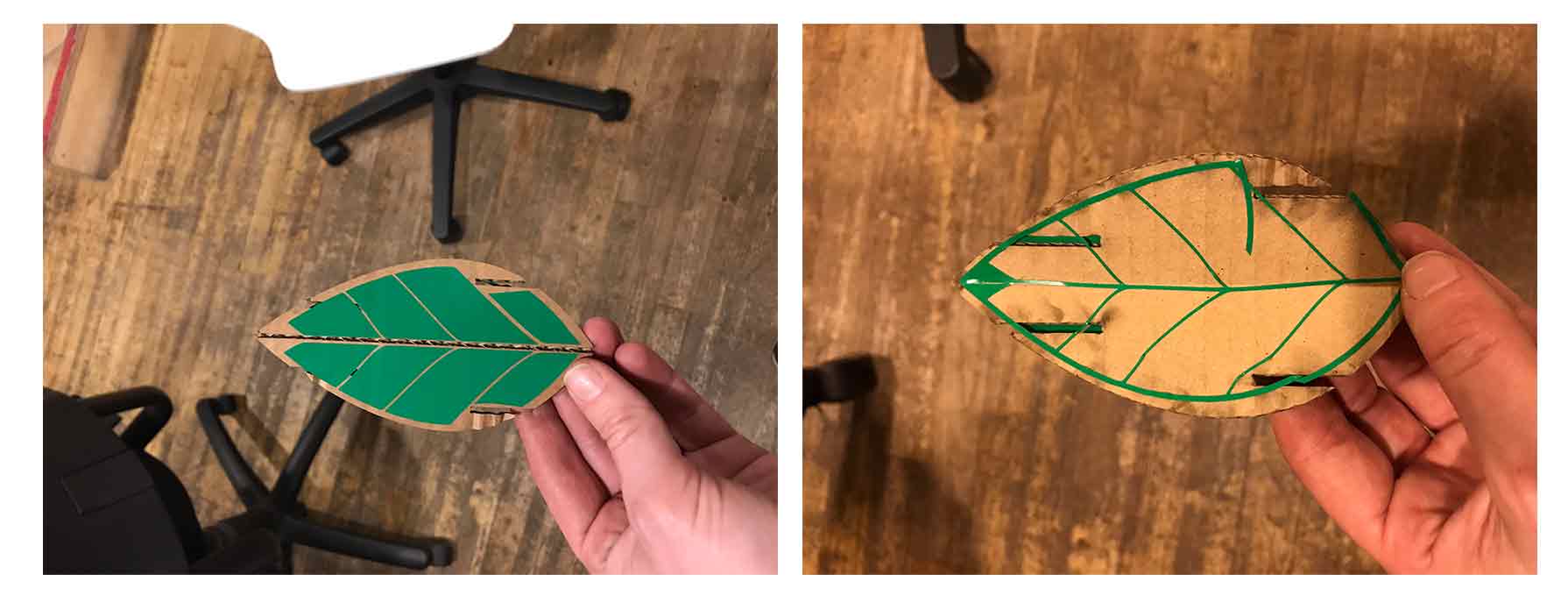 first test of vinyl cutted nerves
Steps for setting up the Vinyl Cutter
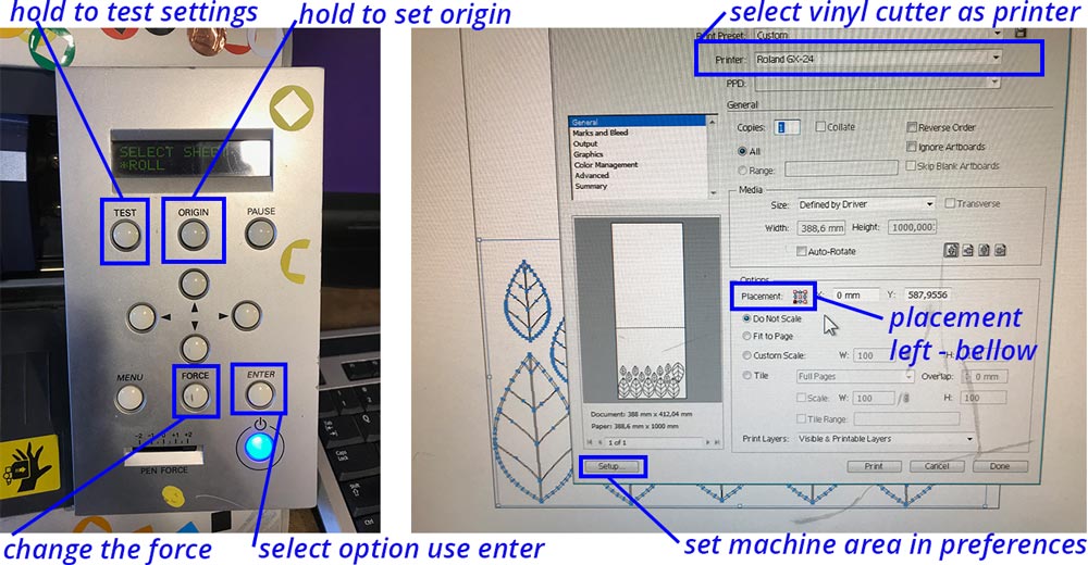 Setup of vinyl cutter
- Place material on the bed.
- Make sure the wheels are on the material and are on the white blocks above the part holding it
- Tighten the material by moving the handle towards you.
- On the menu select roll, when using a role of material, and piece when you only have a sheet of material. Press enter to select.
- Now the machine is measuring the size of the material, it shows the size on the screen.
- Hold the test button to do a test to check the force and speed. For most materials you use force: 110 (for copper you mostly use force: 60) and speed: 10 cm/s.
- Check the test, does it peel away easily, is it cut trough but not through the surface layer?
- Put the material back, move the knife with the arrows and don’t forget to hold origin to set the origin for the knife in relation to the material.
- Go to Illustrator: use the measurement of the machine to set your artboard.
- Set the line-tickness to 0.01 point, view > outline also helps to get a good view of what the machine sees.
- Go to Print in the menu > select position of material bottom left corner
- Go to preferences select the Roland machine > get preferences from machine > this sets the printing area to the size of your material.
- Press print.
 end result
What I did wrong – and how I solved it
This week I made a couple of design to get an understanding of parametric design. Most mistakes were made while setting the parameters and working on Fushion as I’m still not totally familiar with the setup.
Parametric design and constrains mess with my head
My first design wasn’t parametric at all. The second design worked and was parametric but it had some mistakes that I didn’t know how to change. Therefore I started over again with a third design, this one works. I can change the length and the degree of the joints, but when I want to change the width or shape of the leaf I first have to deactivate the degree of the joints. The leaf can’t move because I set constrains on the degree of the joints.
I have some basic notes to myself of things that went wrong and what to keep in mind.
- mirror only works with a straight line
- make axis of mirror an construction line –> I can use this as middle line in the vinylcutter
- first coincident middle line (Av2)
- after that (Av1 en Av3)
- press d > for dimensions
- double click to change / add
- the curves with the control point spline are the end results parameters go on the construction lines
- don’t delete the mirror line you loose the mirror function
Adding the joints makes it difficult
My design went crazy when I added the joints.
- remove the vertical constrains
- to keep the joints straight set them parallel
- set the bottom part perpendicular
- set the angle from one pivot point I still have to figure out how I can change the degree and change the width and shape of the leaf.
Vinyl cutter print option is different
The print option was different than I was used to. So my first print started all the way at the end. You can change this in the print menu. The right setup is the left bottom 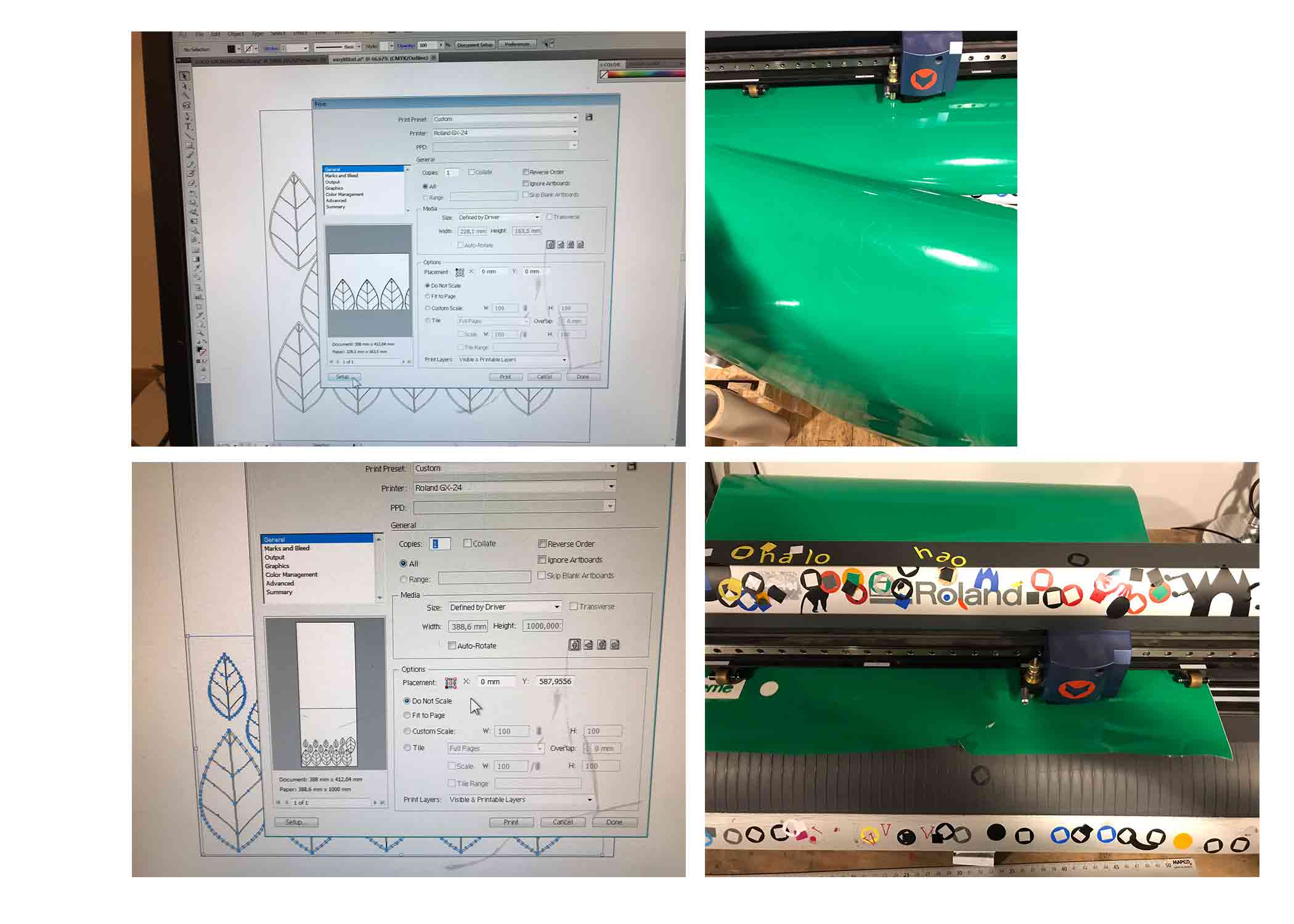 I created the leaf nerves with the vinyl cutter using the file from the laser cutter
What I learned
To design parametric involves a lot more thinking than I thought but it was also a lot fun.
What made me proud!
That I sort of understood the Disney Research paper and that I could use this information to create a parametric leaf. I am still really glad with my Design 2 and I would love to see how I can use this idea also for my 3D-prints and for the foliage of my final project.
Credits and references
References
Beardsley, P., & Chaurasia, G. (2017). Editable Parametric Dense Foliage from 3D Capture. In 2017 IEEE International Conference on Computer Vision (ICCV) (pp. 5315–5324). Venice: IEEE. https://doi.org/10.1109/ICCV.2017.567