20. Project development
The assignment for this and next week is to complete my final project, tracking your progress: what tasks have been completed, and what tasks remain? what has worked? what hasn’t? what questions need to be resolved? what will happen when? what have you learned? This page shows the process of my final project during the full Fab Academy. I tried to link the weekly assignments to my final project. The first part of this page shows my inspiration and these weekly linked assignments. Further on it shows more in detail the development of my final project.
Files, planning and tools
Files
- First strandtest Neopixel adaption for final project
- Second strandtest Neopixel adaption for final project
- DXF-file case Stasha kit
- STL-file connector leaf
- STL-file connector leaf
Overall planning
During the Fab Academy I will work with two two spiral tracks. The basics of both tracks will be to start with one leaf and one branch. From there on I want to further develop my project with more leaves and still one branch. Hopefully it will end up in more leaves and more branches and as end result a tree.
In the first week I made a first initial global planning linked to for each weeks assignment.
 First planning for my final project
Spiral experiments 1: shape and form
What will be the best shape for my tree? Experiment with sketches (week 1), 2D and 3D models (week 3), construction kit (week 4), CNC, 3D print (week 6). My inspiration for this spiral planning starts with Mondriaan’s trees (as also shown in week 3).
Inspiration abstraction
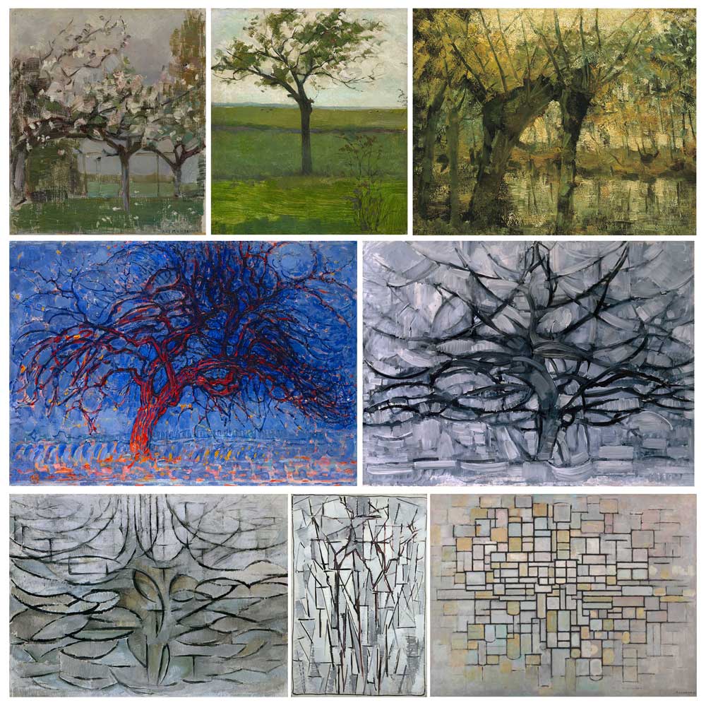 Piet Mondriaan’s development towards abstraction based on trees
Spiral experiments 2: interaction
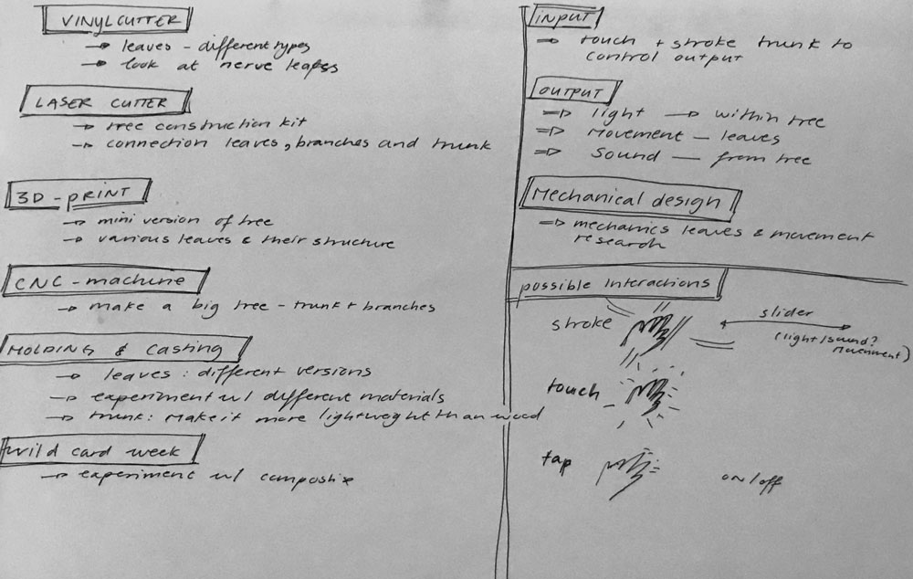
What will the interaction be? For this installation I want to recreate the feeling of lying under a tree. So the basic interaction will be the movement of leaves, followed by light and maybe sound effect. I will further develop these concepts in the input and output weeks of the Fab Academy
Possible interaction:
- movement of leaves
- light –> how to recreate the shimmering of the sun
- light –> maybe recreate the stars through the foliage
- sound?
Inspiration kinetic interaction
For inspiration I traveled to Rotterdam for the exhibition Action <-> Reaction: 100 years of kinetic art at the Kunsthal.
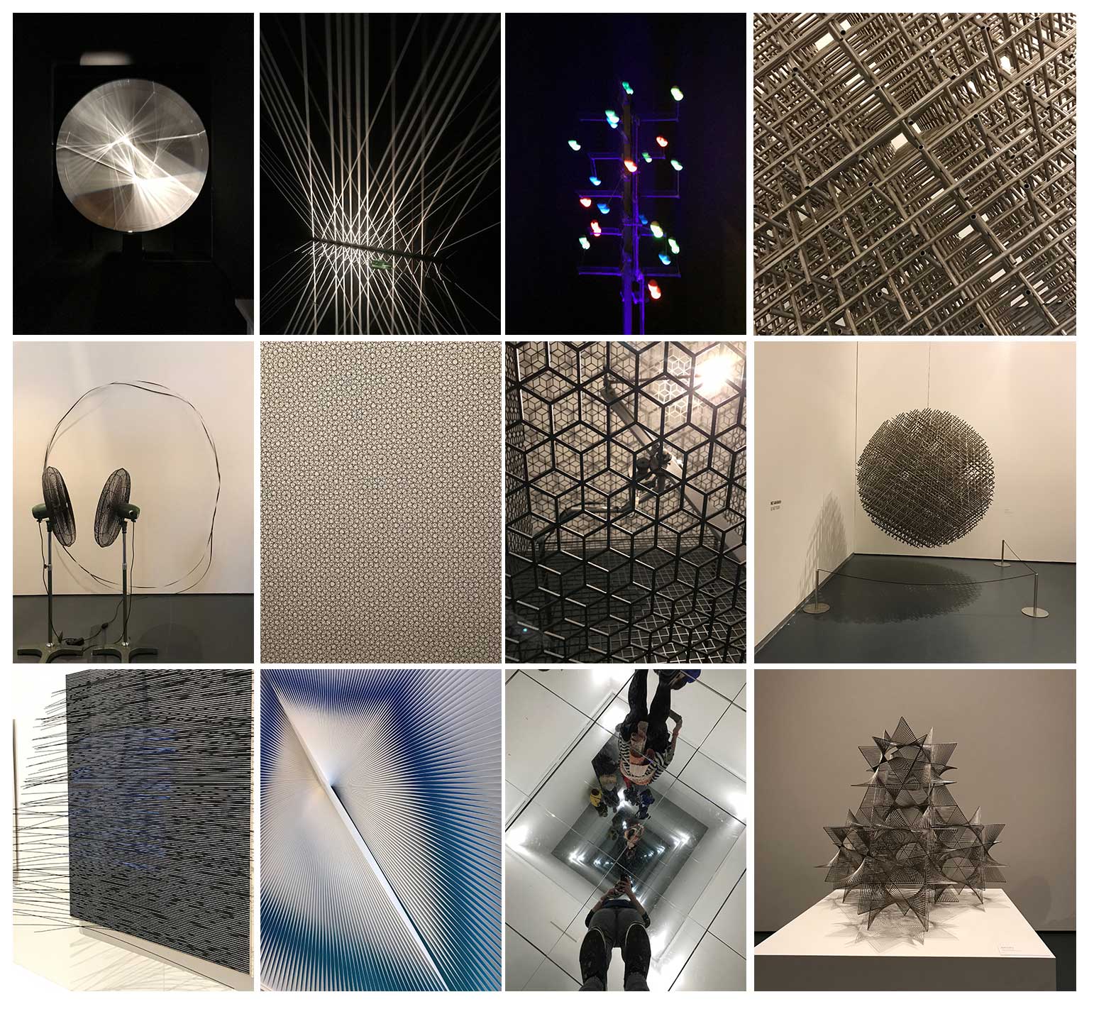 Selection of artworks I saw at the Kunsthal in Rotterdam
Action <-> Reaction: 100 years of kinetic art
With the regional review Julie from the Sorbonne Fab lab shared an inspiring publication from Disney Research about ‘The Design and Fabrication of Kinetic Wire Characters with me.
Bend-It: Design and Fabrication of Kinetic Wire Characters (Xu, Knoop, Coros, & Bächer, 2018)
My initial idea for a final project
My initial idea for a final project is that I want to make an interactive tree. The seed of this idea was planted a couple of years ago when my niece Coco was born. I thought of making her a mobile for above her crib. While I was thinking about this idea, I notice that she was especially happy when her parents lay her down her under a tree. Or whenever we would walk the woods she would look at all the leaves above. This made me think of my own childhood having tons of fun in the garden, climbing trees, and looking at the clouds and stars in the sky.
As an adult living in a city apartment I realized that I miss this feeling. It’s quite difficult to get a daily doses of experiencing the woods or lying under trees. While its actually one of the nicest ways to dream away while looking at the sky between the branches and the sun or stars shimmering through the foliage. Therefore I want to re-create this experience with my final project.
Process of project development during the weeks
I try to connect my weekly assingments with my project development.
Week 1: sketch and brainstorm
The development of my final project idea started with a quick brainstorm in my notebook. I just thought about all the things a tree made me think of like trunk, branches, leaves, the woods, seasonal change.
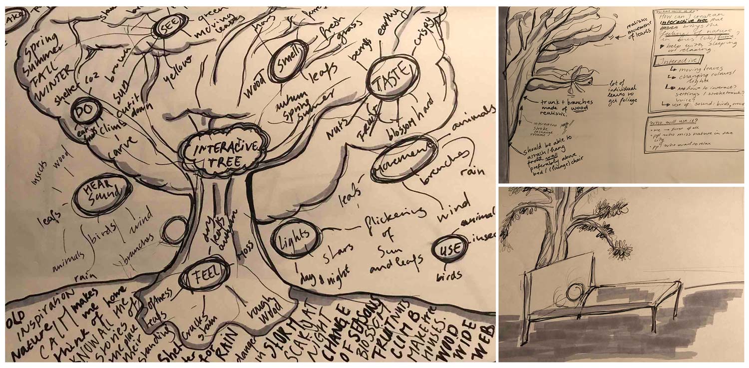 brainstorm and first sketches of my final project idea
A tree is already interactive of itself so I wanted to have a brain dump of all the interactivity it already has like climbing trees, changing of seasons, and branches moving in the wind. It makes sounds, it changes light, it changes shape, animals use it as a home, it provides food, it communicates with other trees (something I would like to research more). This brainstorm led me to the following question:
“How can I develop an interactive tree in a city home that re-creates the experience of lying under a tree looking at the sky while dreaming away under the foliage and stars shimmering?”
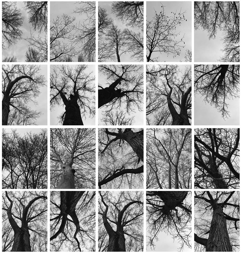 Selection of tree pictures made en route to Kunsthal in Rotterdam
Week 3: 2D and 3D Sketches
In the third week I made sketches first by hand which I edited digitally in 2D. This is a possible representation of my project. I still want to test out different shapes and imagery.Therefore I started with different types of leaves and a branch.
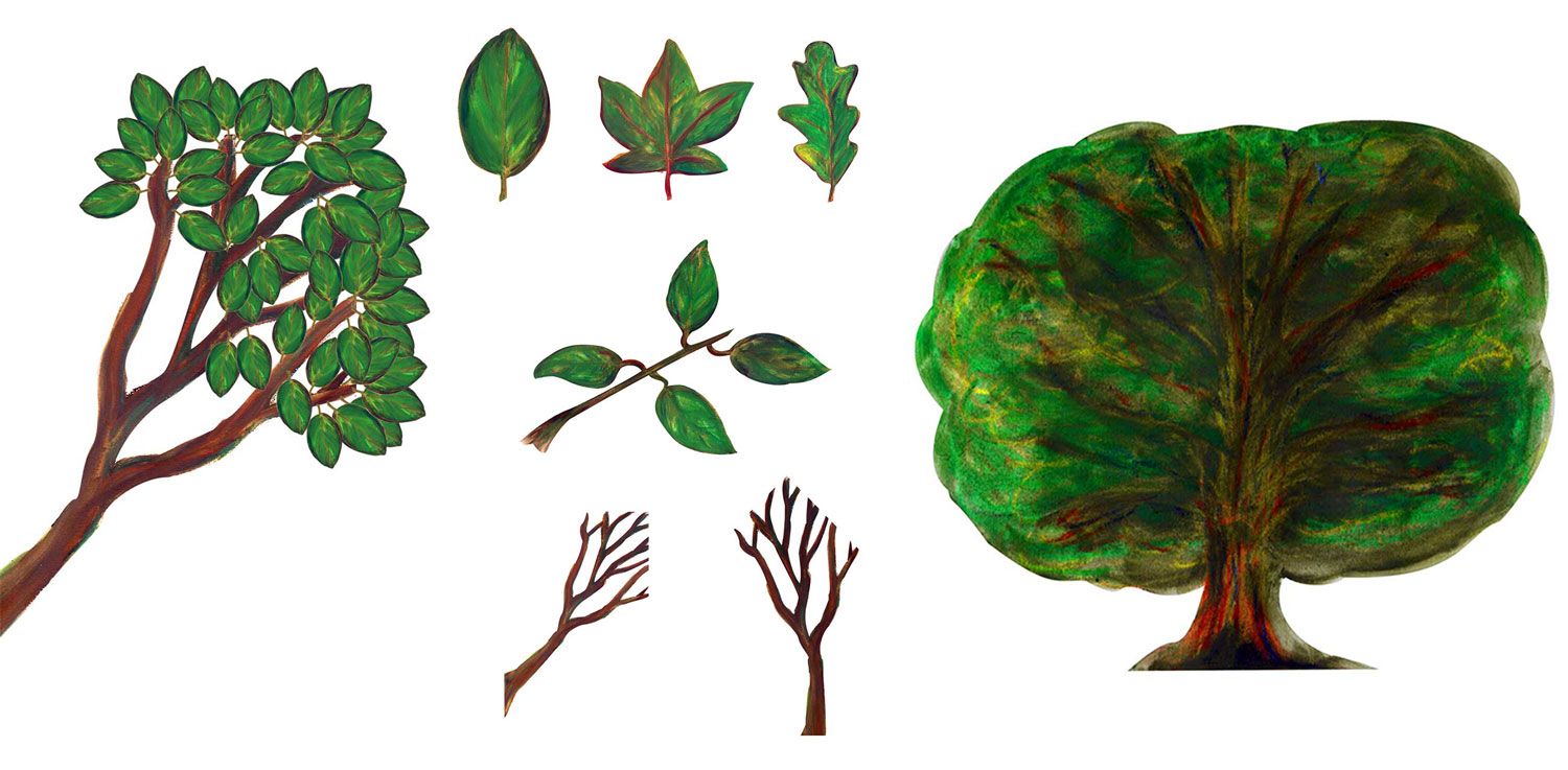 2D models of my project
I also tried to experimented with 3D models to represent the shape of my project.
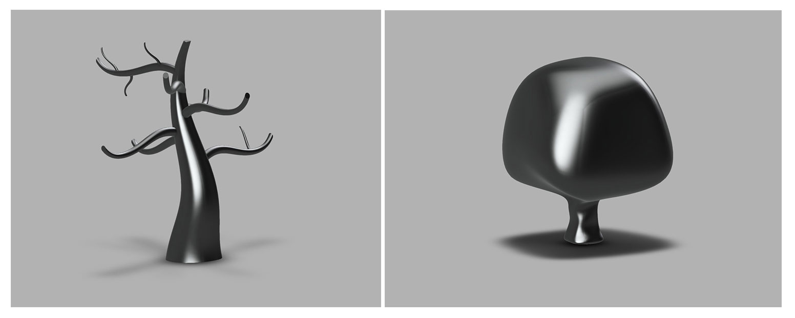 3D models of my project
Week 4: how to make a tree from one leaf
I wanted to experiment with the concept of modularity when working on the construction kit as this really suits the assignment. My goal for this assignment was to get a better understanding of each part of the tree starting with the leaf. Therefore I gave myself constrains related to my final project for the design of the press-fit construction kit.
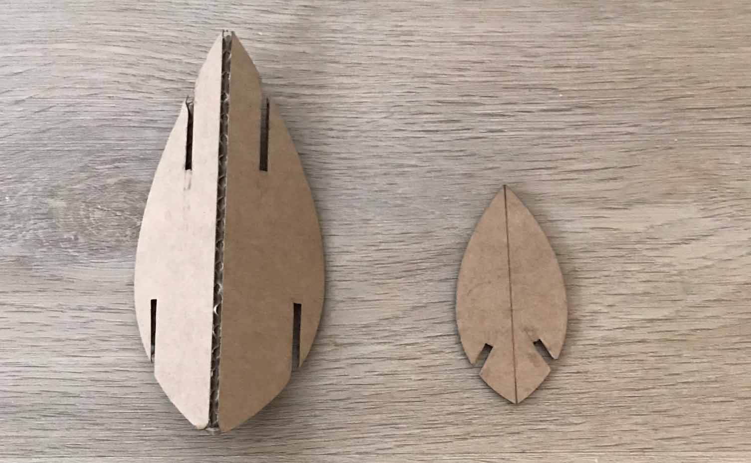 Leaf construction kit
My constrains:
- Design one piece that can be used to construct more complex shapes.
- This piece should have a leaf-like shape
- I want to build a tree with this leaf.
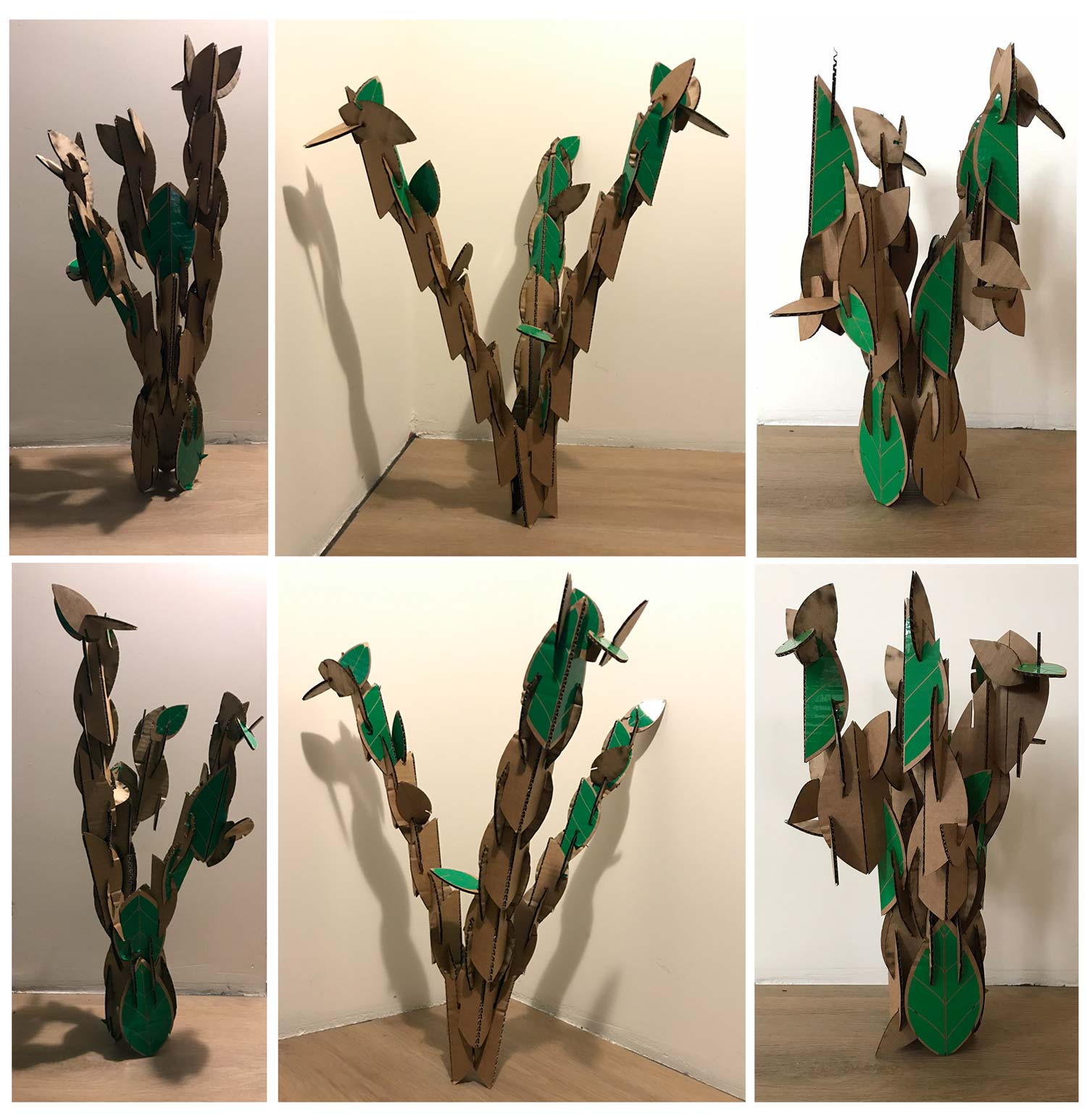 Different tree like shapes made from one leaf
Week 5: inspiration while debugging
While I was debugging my tinyusb because I got the same error over and over again. I looked into the Fab Academy archive to find students with the same error. One of them was Jie Qi she forgot to install the driver. While I was looking at her error and read about her project. Her interaction ideas and techniques with origami and paper folding is good inspiration for my final project.
Electronic origami: Input/Output blintz folding by Jie Qi
Week 6: 3D designs and prints
This week I focused on the possible shapes and forms of my final project while learning to design 3D with Fushion 360. More details can be found in the documentation of week 6.
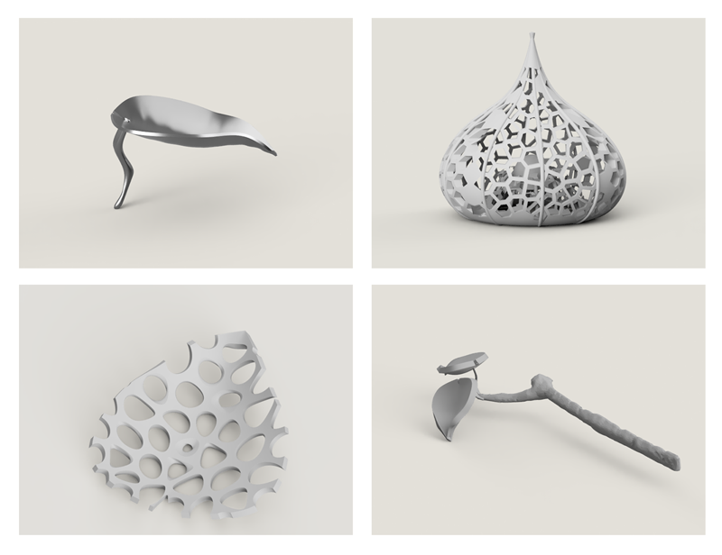 Overview of my 3D designs
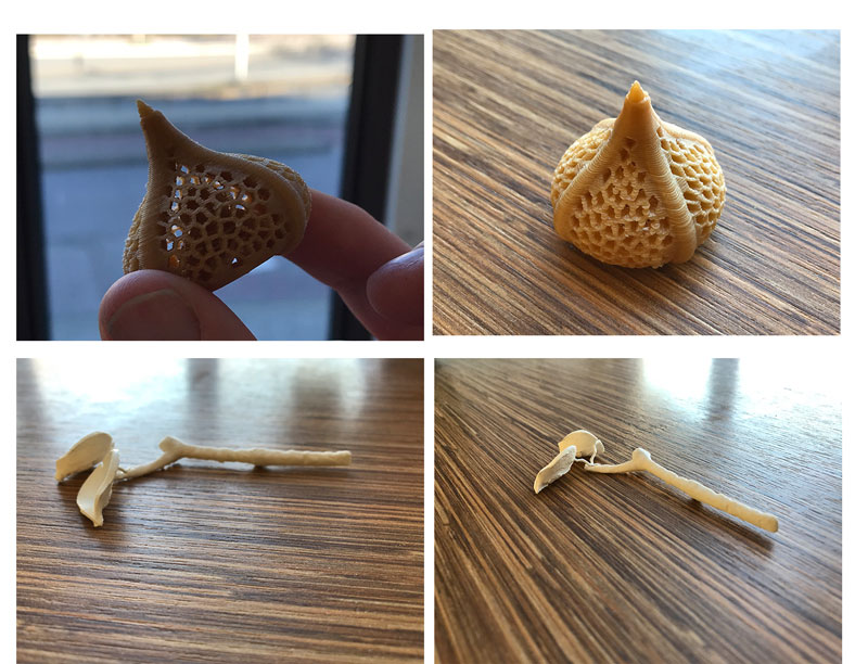 End Result 3D prints
Ever blooming mechanical tulip
This week Luc from the Sorbonne University shared “Ever Blooming Mechanical Tulip” by Jiří Praus with me on our regional review Slack channel. This is a inspirational and touching project for me especially liked to possible interaction for my tree. It reminds me a bit on the inspiration from last week by Jie Qi
The Ever blooming mechanical tulip by Jiří Praus
Week 7: Robots love music
For inspiration for my final project I went the museum Speelklok where you can walk through the wonderful world of self-playing musical instruments. They had an exhibtion called Robot Loves Music which showed their collection of self-playing instruments with a human figure. In addition they have a big collection of automata and organs.
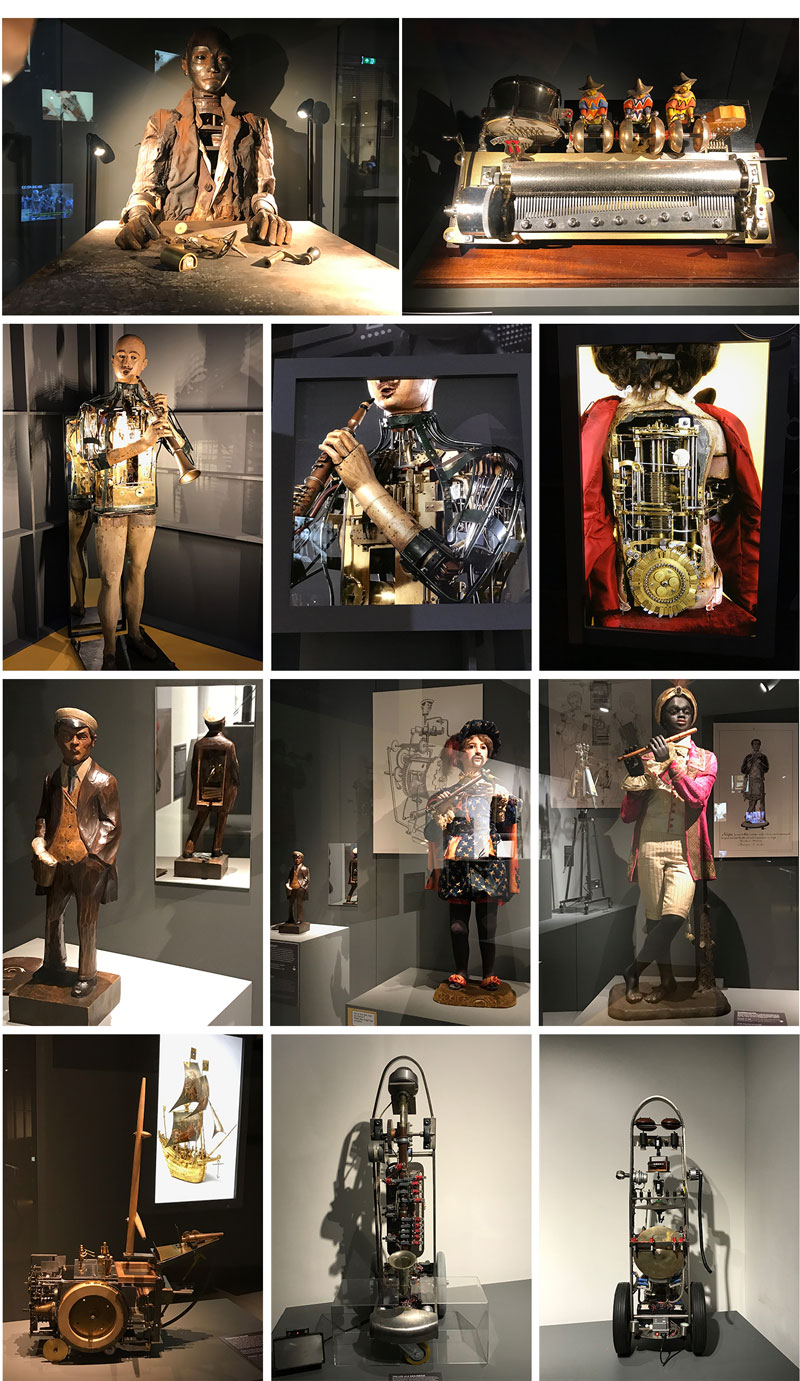 Robot loves music exhibition at the Museum Speelklok
Henk send me inspiration as well the Blooming Rose, it’s inspired by the Tulip Luc send me last week. What’s nice about this project is that it has a lot of documentation.
Week 8: Chair
This week I made a chair in the shape of a leaf.
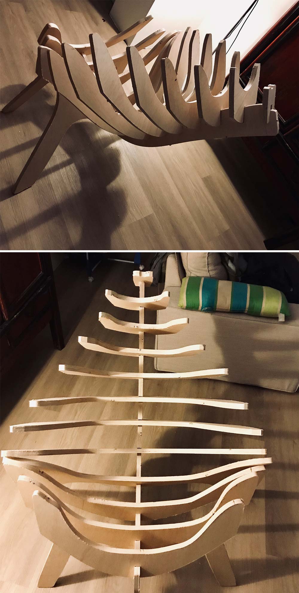 Chair in the shape of a leaf
Week 9: Studio DRIFT - Tree of Ténéré
My colleague Maaike gave me great inspiration this week, she showed me the interactive installation The tree of Ténéréby Studio DRIFT, an Amsterdam based artist collective that explores the boundaries of technology art and nature. The Tree of Ténéré is a large-scale LED artwork conceived and created by Zachary Smith. The leaves of the tree illuminate with ‘light flocks’ in response to visitors’ movements, heart beats and brain activity (Howard, 2017).
Tree of Ténéré by Studio DRIFT
Week 10: Molding and Casting
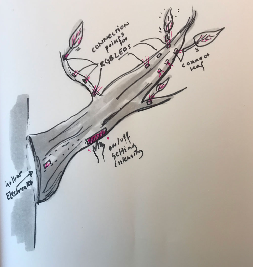
For my final project I would like to cast PMMA optical fiber within a leaf. This way I can make a more modular system, where I connect each leaf to one Neopxel, like the sketch below.
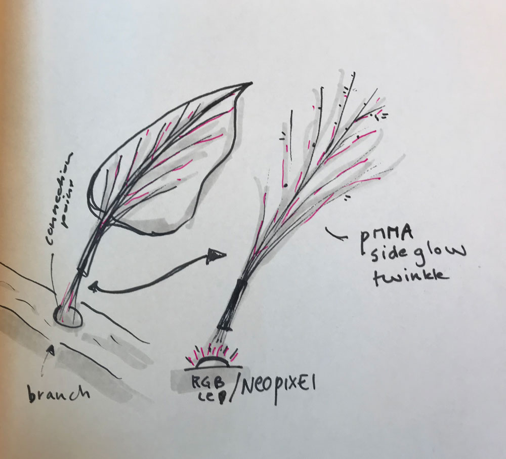 Each leaf will have PMMA fiber connection with RGB-LED
For molding and casting I created a leaf mold. I designed it in such a way that it should be possible to add the PMMA. I still have experiment with different casts.
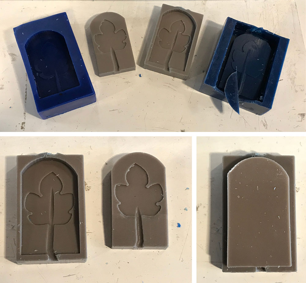 Mold for leaf
Week 11: Input devices
For this week I wanted to work on my first spiral for the interaction. The main interaction I want in my artificial tree is to put it on and off with a tab and to change the intensity of the lights and movements with a stroke up or down. So I used this week to find out how a step response sensor works and how I could create my own touchpad.
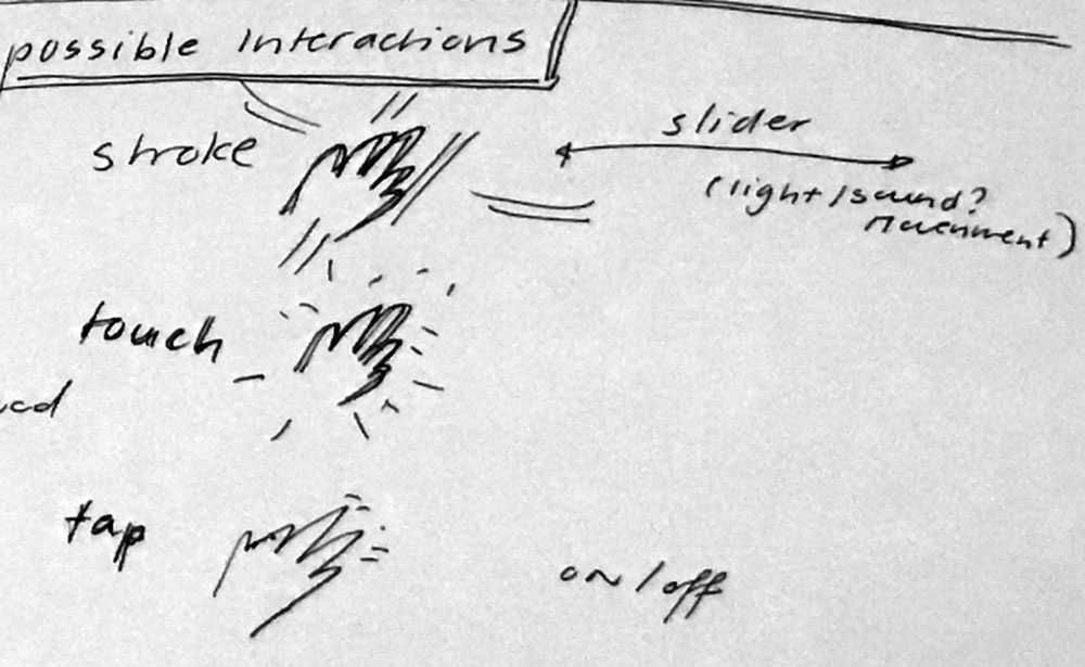 First ideas of interaction for my final project
I experimented with different versions of the touchpad, this way I could find out what shape and form could work for a possible interaction display.
 Leaf shape touchpad
 Tree shape touchpad
Week 12: Output devices
This week I went to STRP and MU for inspiration for my final project.
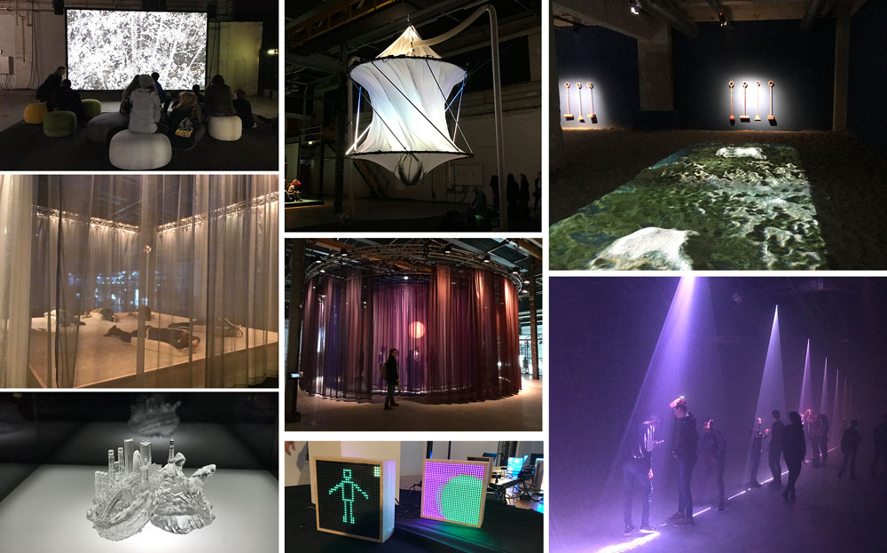 Exhibition at STRP Festival 2019
And this week I wanted to experiment with the output possibilities for my final project. At the moment I’m thinking of two possibilities for lighting up the leaves in my tree.
- Use a RGB LED-matrix to light up glass fiber in the leafs.
- Use a RGB LEd-matrix for each individual leaf.
My preference for my final project would be the first option, as I think this will give the most beautiful result. However I think it’s also the most difficult option. Therefore I wanted to start with created my own small RGB LED-matrix.
My own RGB Led matrix on a leaf shaped board
Week 13: Implications and Applications
 Main construction tree
- The main branch (or trunk) of the tree: I will use composite to create the branch of the tree. I want to make this part hollow so I can fit the electronics inside.
- The leaves: I’m not sure yet which material I will use for the leaf it self. First idea is to cast parts of flexible material or to use fabrics.
- The lights: I want to use RGB-LEDs, Henk suggested to use Neopixels.
- Light effect: In addition to the RGB-LED I want to create a light effect within each leaf. I want to use glass fiber or PMMA side glow twinkling fiber inside each leaf.
- Movement: My main idea for now is to use Flexinol to create subtle movement of the leaves.
Week 14: Networking and communication
This week I designed and made a board that I can use as a driver for my Neopixels. I added a header so I could add as many pixels as I want. I can also reproduce this board to make smaller nodes of Neopixels.
![]() Neopixel board: easy to add more Neopixel with the use of a header
Neopixel board: easy to add more Neopixel with the use of a header
Week 16: Interface and application programming
I kept the assignment simple for this week so I could understand it in the time I had. And I did my first spiral for the programming of the lights in my tree. I wanted to have four different settings, because I understand the code better it will be easier to change this and to add setting to this code.
My interface
- the green square turns the light green
- the red square turns the light red
- the blue square turns the light blue
- the white square turns the light white
Interface working together with my Neopixel board
Week 18: Wild Card Week
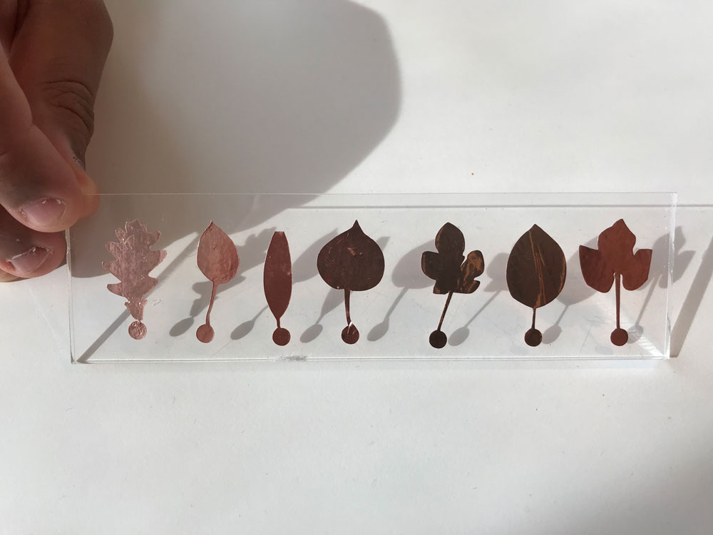
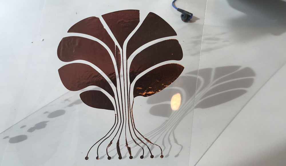
 Test results leaves with light and optic fiber
Week 20: Project Development
From this week onwards I could fully focus on my final projet.
Planning
Because we only have two week left to finish the final project, planning and timing is really important. I divided my time in three phases steps: testing and prototyping, making and developing, assembling and debugging.
Phase 1: testing and prototyping
- movement: Prototype the movement of the leaves, try out different ways of creating a smooth movement without a motor.
- electronics: Prototyping the electronic. Go back to Arduino to test the capacitive touch library, understand how it works and connect it with the Neopixel board
- frame: The frame of my project will be the branch or trunk of the tree. I will use wood and slicer to create this. So I first have
Phase 2: making and developing - June 5:
All the testing and prototyping must be done. From the 5th of June onwards it’s time to finally make each part.
- Mill a new board with the Protmat
- Make sure the wiring is correct and nice
- Make casing for electronics and wiring with 3D printer.
- Make system of the leaves.
- Make the frame using the Shopbot.
Phase 3: assembling and debugging - June 12:
All individuals parts must be finished.
- Debugging the parts
- Finishing documentation
- Preparing the presentation
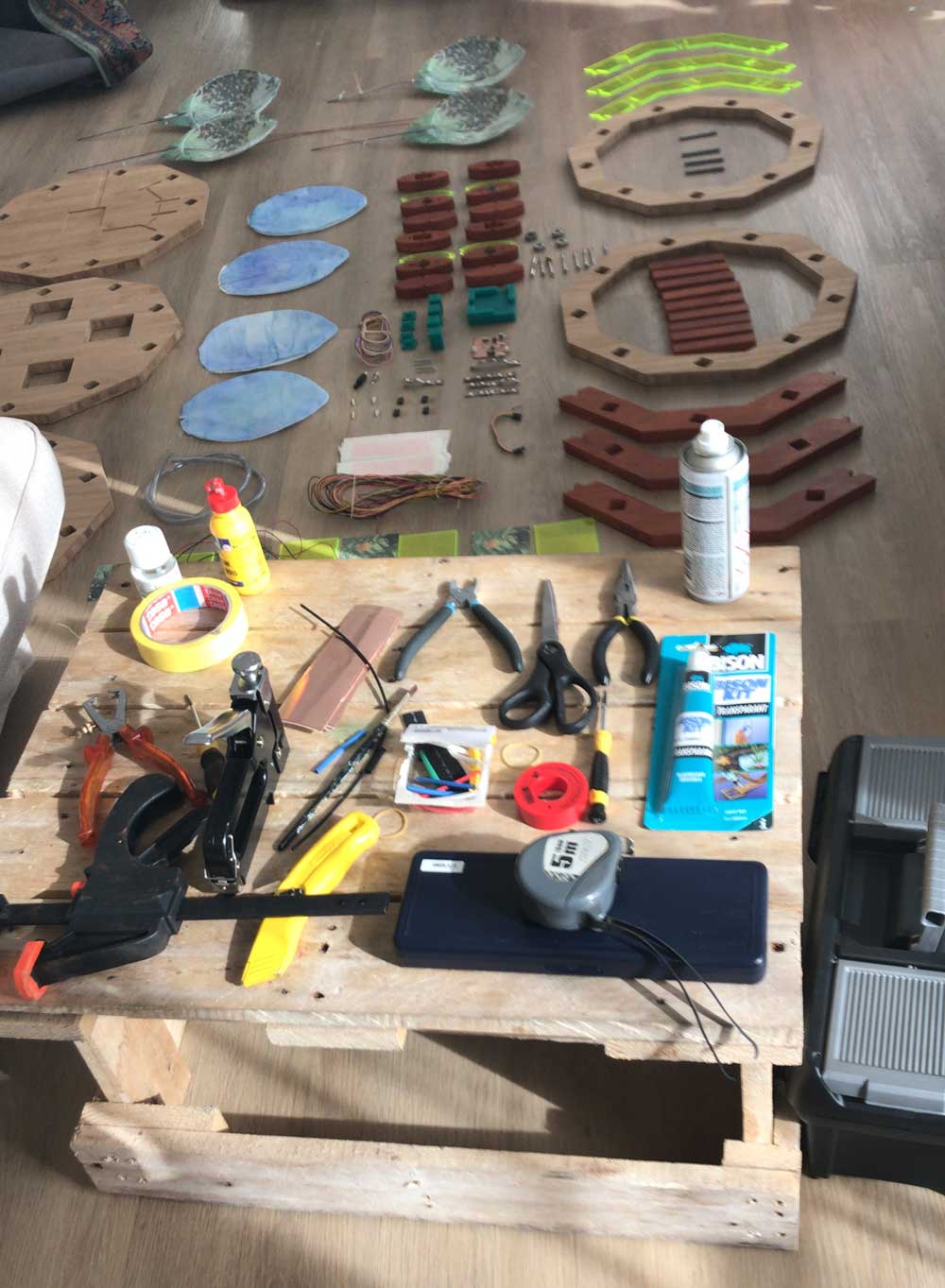
Machines and software used
- Laser cutter
- Vacuum former
- UV printer
- Shopbot
- Vinyl cutter
- Protomat
- Ultimaker 2
- Circuit Cam
- Adobe Illustrator
- Fushion 360
- ExactFlat
- Slicer for Fushion 360
- Adobe Premiere
Links used for generating Gerber Files
- Tutorial on Circuit Cam and Protomat by Loes Bogers
- Tutorial on how to generate gerber and drill files form kicad
What I did – step-by-step
Based on the Wild Card Week I changed the core idea behind my design, as I described it in the Applications and Implication week because I thought composites would give me the best opportunity for the frame and connecting the leaves together with optic fibers. However, the results was not as I wanted. In the time I have and in combination with my skills I realized it won’t look nice enough when using composites.
Step 1: Prototyping movement
For my final project I really wanted to test if I could add movement because that would give an extra effect to my final project.
Using Shape Memory Alloy
I did a test with Shape memory alloys a couple of weeks ago. I used the documentation by Jie Qi for tests. the first result is nice and works well with a fabric leaf.
Testing the shape memory alloy, Flexinol, with fabric fake leaf
This gives a nice results but needs a lot more testing. I have to see if this is useful if I create a bigger units with leaves.
Using springs
I still think that my project will be more realistic when I could add movement to my final project. However, I don’t want to use motors because this would make too much noise, hence the tests with shape memory alloys before. I wanted to create a motion that keeps on going, link a swing or pendulum, but without a motor, because this makes to much noise for the sleeping room.
- I used a torsion spring
- I made a very quick prototype
Testing movements setup with springs
I made another simular quick prototype, but this time with different springs. The supplier of springs Alcomex gave me great advice and send me some samples to test. Due to the time I have it’s still really hard to fine tune the movement and get the right measurements for the final project.
- Make wooden connectors where the leaves can be placed inside.
- Use two in stead of one bearings to get a more stable result.
- Use light wood, so the moving construction won’t be too heavy.
- Connect the wooden connectors to the frame
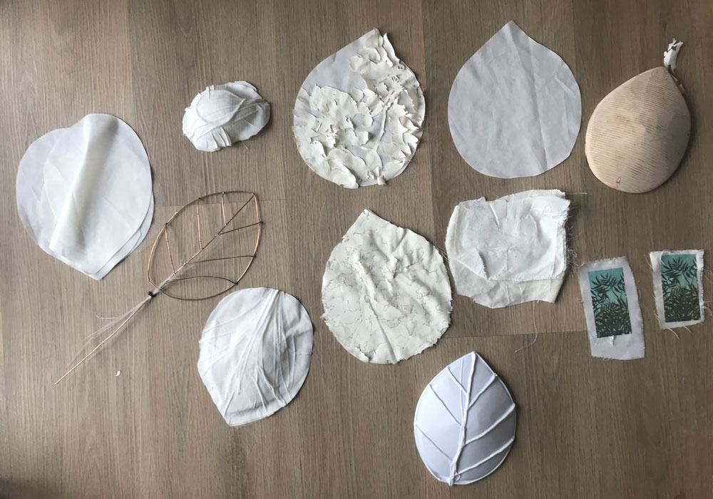
Step 2: Bigger units of leaves
Based on the wild card week and the molding and casting week I realized that it will take a lot of time to create individual leaves. Therefore I decided to create bigger units. I want to represent the idea of foliage for this I don’t necesarily need individual leaves I could also use groups of leaves, I was inspired by the Shadylace parasol of Droog Design and by camouflage netting.
Testing the leaf units
Before I created the final version of my leaf unit I did several tests.
soldering a frame
I made a construction with iron wire and soldered it around a piece of material laying around. I soldered it in the shape of a leaf, inspired by the The use of this technique is inspirered by the “Ever Blooming Mechanical Tulip” of Jiří Praus.
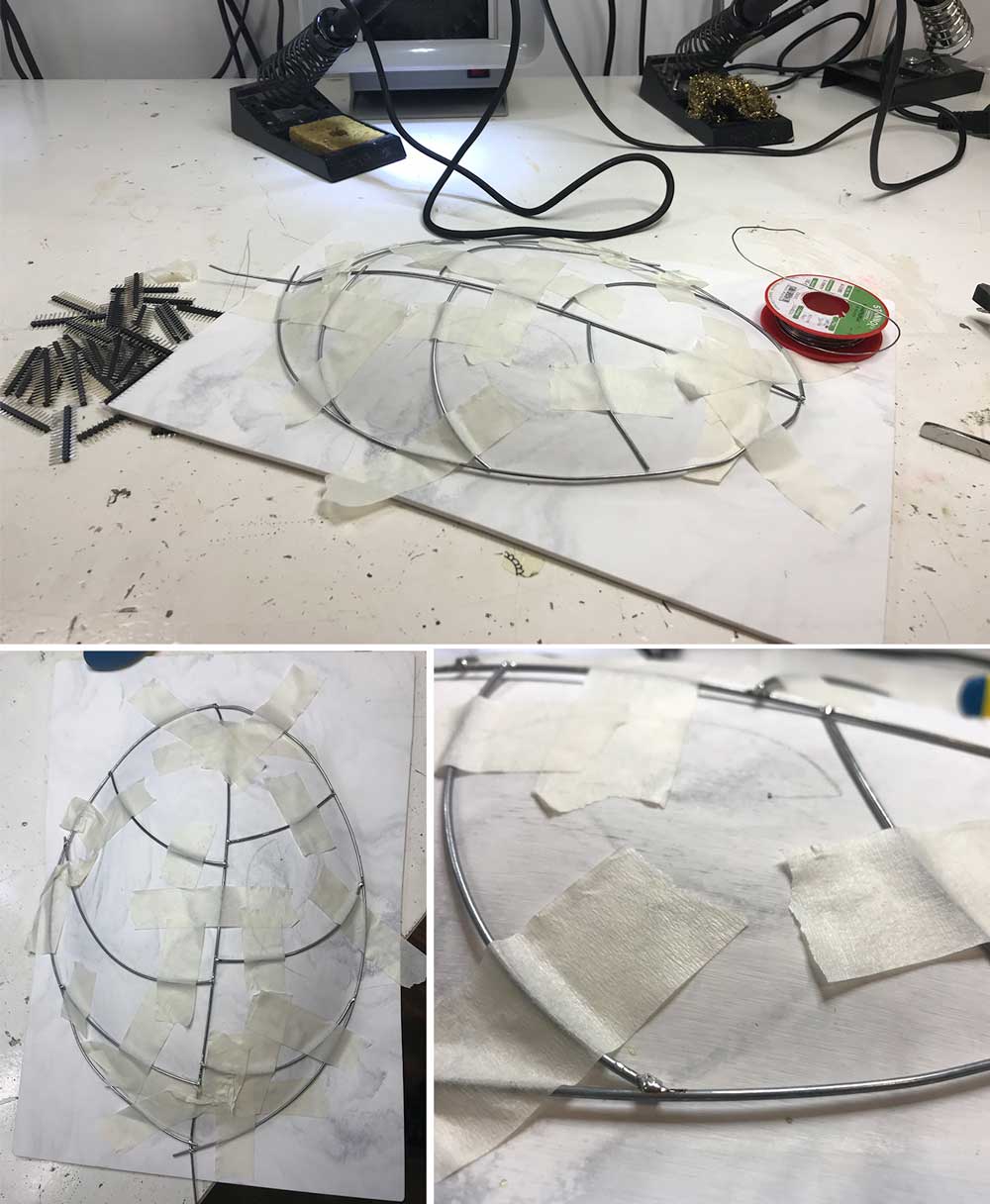 First frame test leaf unit
foliage with fabric
In addition, I used some left over canvas to create foliage with the laser cutter. I place to layers on top of each other and I really liked the effect of having a layer more lose on top.
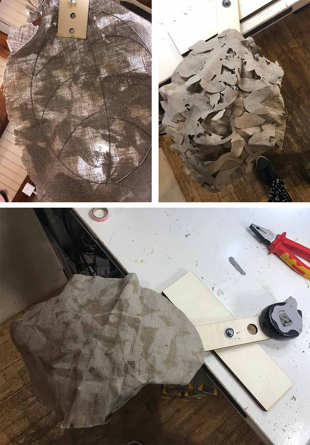 Test foliage made with canvas
This test has a nice result. Next step is to use better material and find a way to connect the fabric and the frame on nice way
Testing new leaf design with motion
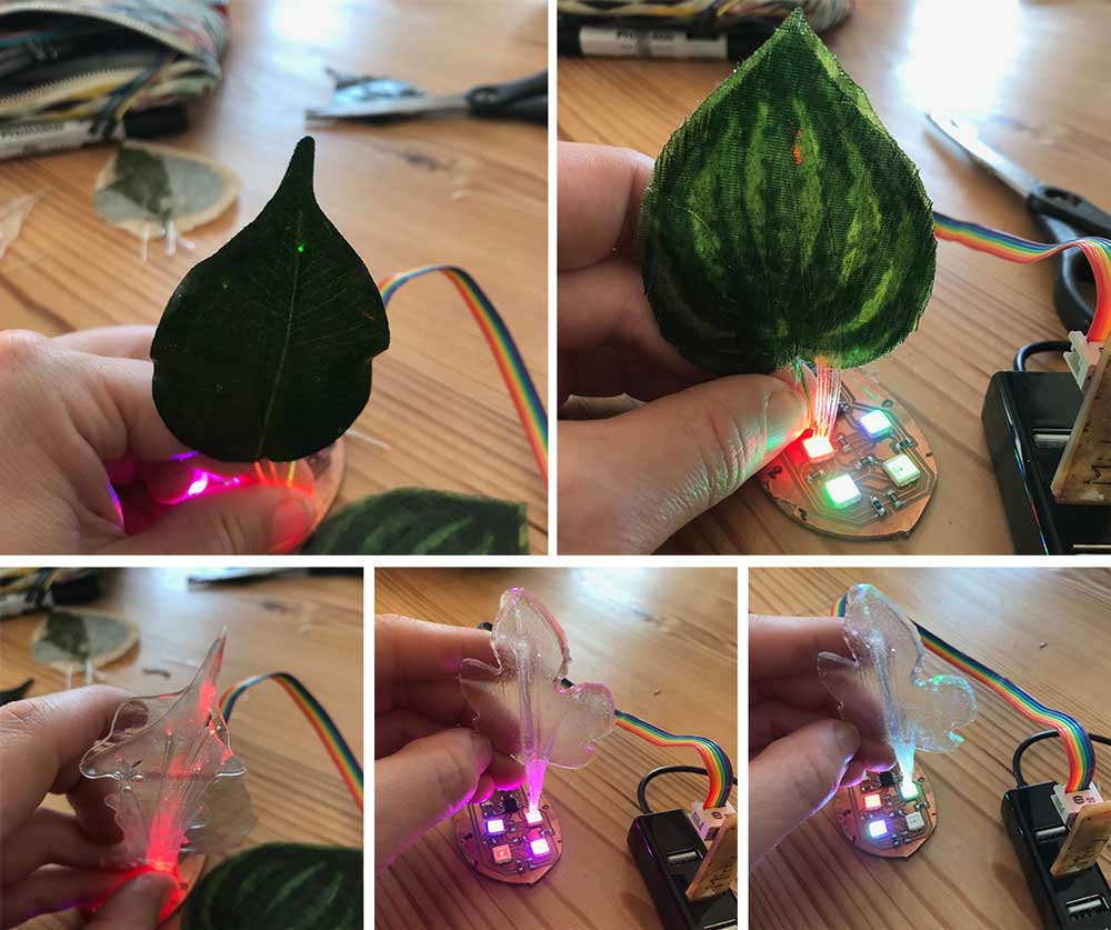
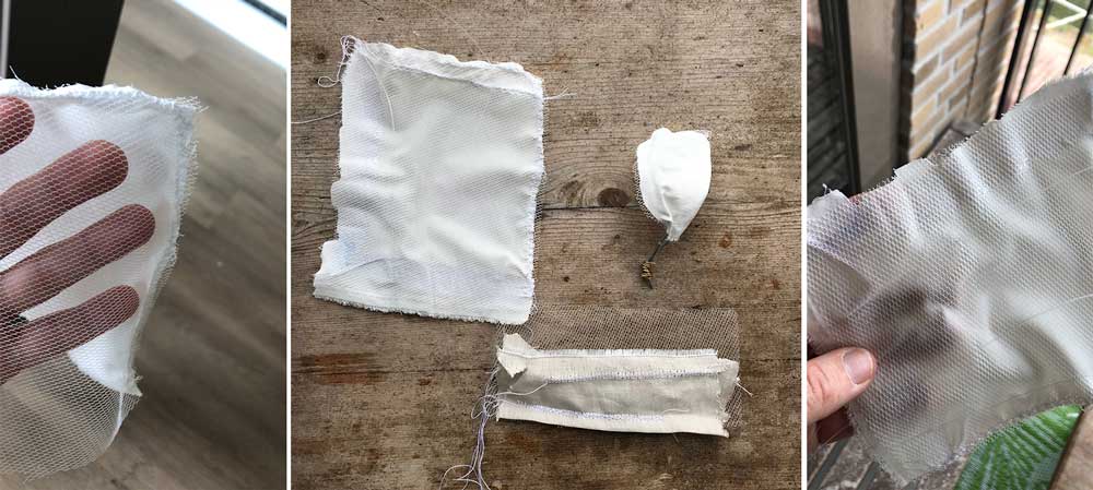
adding the optic fiber to the leaf.
After my first test with the canvas fabrics, I wanted to find a way to include the optic fibers and a way to include the frame. Again I did tests to find the result I wanted, using sewing machine and one hemming strips that you can iron fabric together. First it’s import to sand the fibers. After this I will weave them through the tulle netting to get the shape I want. There’s a very nice tutorial on Instructables on how to create Color Changing fiber Optic Fabric by Spookydonuts. I followed the steps to see how it would work.
 Testing optic fabric
The results are nice, I will use this in my final tests.
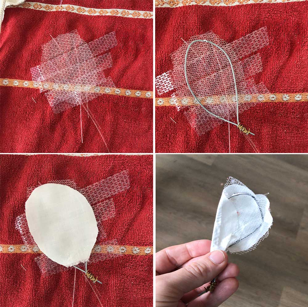
Fine tuning the design
Based on the test above, I did a similar version but this time, I used polyester fabric in stead of canvas, I created a mold specifically for the leaf frame and I used the vacuum former to connect the leaves.
making a mold
To wire the copper wire nicely in a leaf shape, I created a mold. First I made a very quick and dirty version, but this didn’t work as well. So in the end I created a mold using the slicer tool in Fushion 360. Normally I would have used the Shopbot and foam to create this. However in the end I used the laser and plywood because the lab was closing and this way I could finish my mold at home.
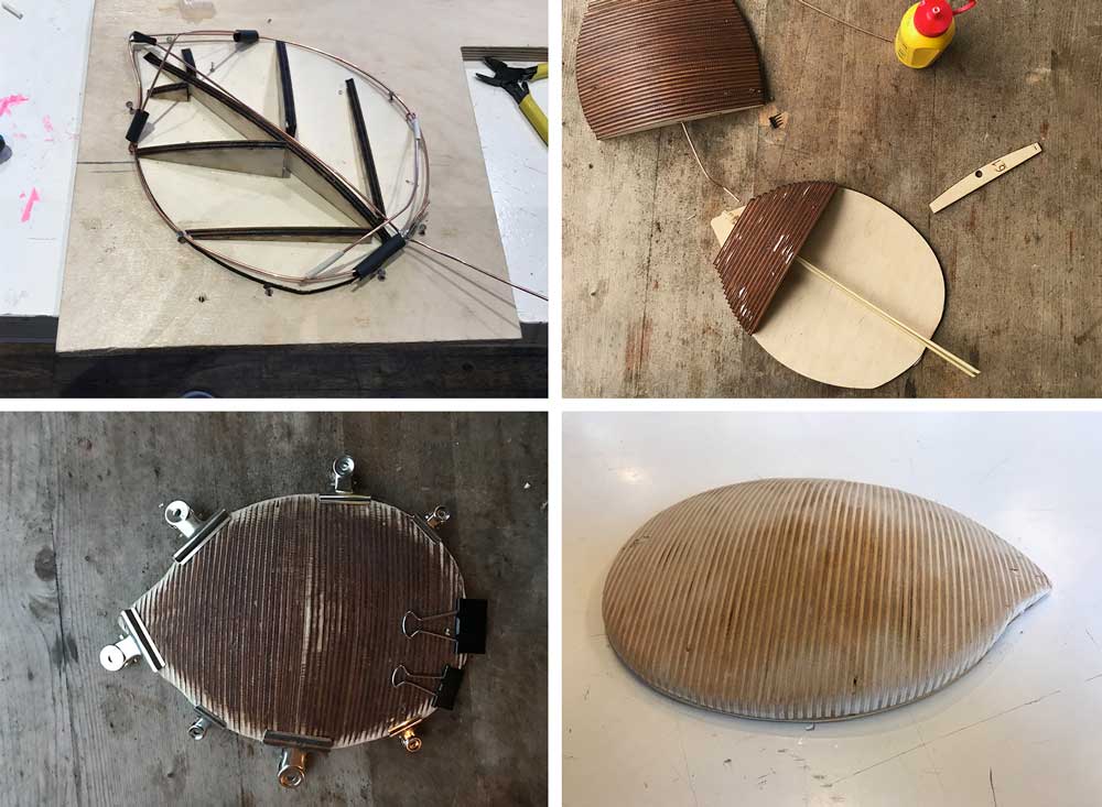 Mold for creating the leaf.
I make the frame with copper wire and soldering it together based on the mold. Using this mold gave a much better result.
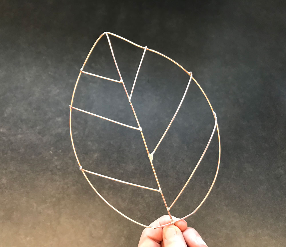 Frame of the leaf made with copper wire based on my mold
making the leaves
I also did some test, how to get a nice connection with the leaves. And if sewing would give the best result or not.
 Testing sewing the parts together
After this I looked into using hemming strip made of nylon. It’s easy to use you can iron to parts of fabric together. This worked well. My next step is to test this with the vacuum form machine. This should give a nice finish.
 Testing using iron and hemming strip to glue the parts together
Both worked kind of nice. the hemming strip get a more clean cut end result. I will use this layering in the vacuum former.
using the vacuum form machine
Finally I combine the parts of the leaf in the vacuum machine. I did a lot of different tests to get a good idea of how and if this would work for my final project.
 Testing how to connect the leaves with the vacuum former
It didn’t gave the result the way I wanted, but I did learn a lot and got good insight for my final production:
- The frame system doesn’t work with this idea. It slips out or moves to much. I don’t have enough to control to get the right finish.
- Still the best works with the lose ends on top, however this is hard to connect and fragile.
- the polyester works really nice in the vacuum former and has the result as I thought.
- I also did an experiment with polystyrene, and this had a nice effect with the optic fibers.
Step 3: Getting the electronic to work
I want to use the capacitive touch with my Neopixel board.
- First I tested if my tree board still works with touchpad. this is difficult it’s not really precise and it gives different values. For me I think this is too much noise to use the values consistent for my final project. In addition, it’s more difficult to adjust because I’m not fluent enough with the C code.
- I worked with a breadboard and an Arduino to test the capacitive touch and the Neopixel board. Because I understand this a lot better and I can work with the given libraries. This gives me more flexibility for the programming part. Decisions made:
- I will use the basic design of the Satsha Kit because this gives me more memory to use which gives me more flexibility to use different libraries and add more part in the future.
- I will include the capacitive touch and the Neopixel connection within my Satsha Kit.
Designing my board
I want to adjust the Satsha Kit on such a way that it fits the element I need for my final project.
- Capacitive touch sensor(s)
- Neopixels
- FTDI-connection
- ISP-connection for programmer
- Options for add-on in the future
- External power source
When I made these schematics. I designed my board in KiCad, like I did in the other electronics weeks. The steps I took:
- Importing the schematics of the Satsha Kit into KiCAD.
- Redrawing the schematics in KiCAD, because th import from Eagle didn’t work. It didn’t connect the lines.
- Adjusting the parts for my final project adding:
- four 1M and one 10M resistors on five pins for the capacitive touch, I added one different one to see what the effect would be. And again to give flexibility.
- three connections to be able to add Neopixel strips. I want to keep the option to add more than one strip. So the connector had a GND, VCC, and 3 Data out pins.
Finally I also added a power plug so I could connect my project to wall power. I used this one for the power jack:datasheet jack
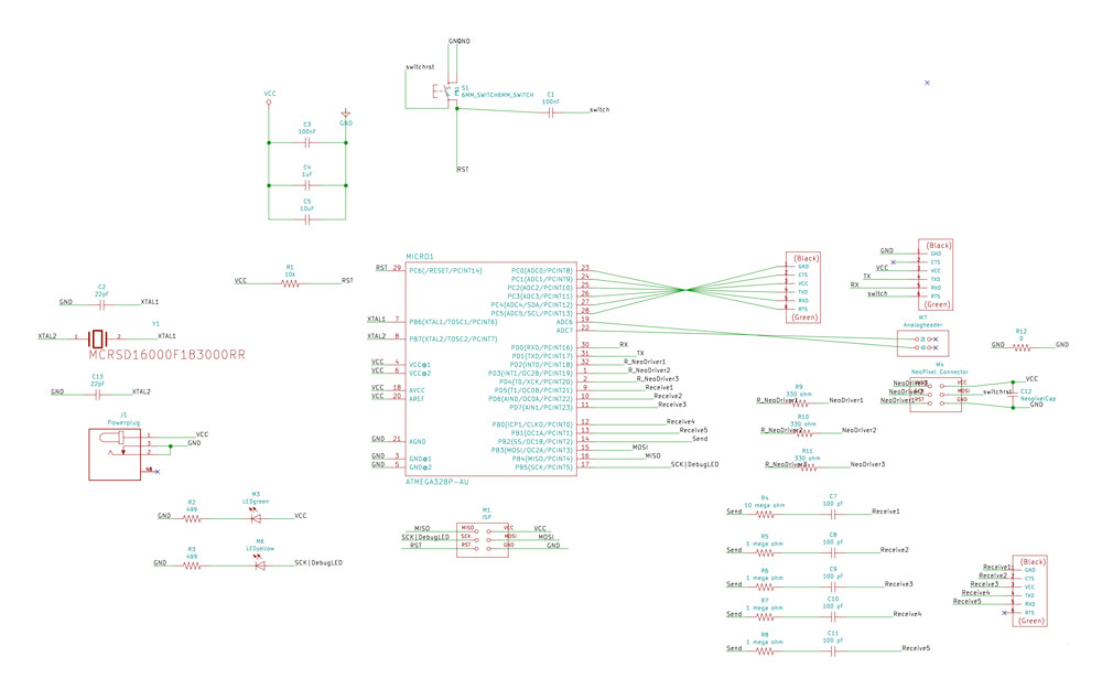 Schematics of my satsha Neopixel touch board
Side note: I used the footprint of the FTDI-header for two other parts because I wanted headers on the side. I like to us the FTDI header for this as this gives more stability. Plus it fits nicely with the physical design of the chip and the amount of pins.
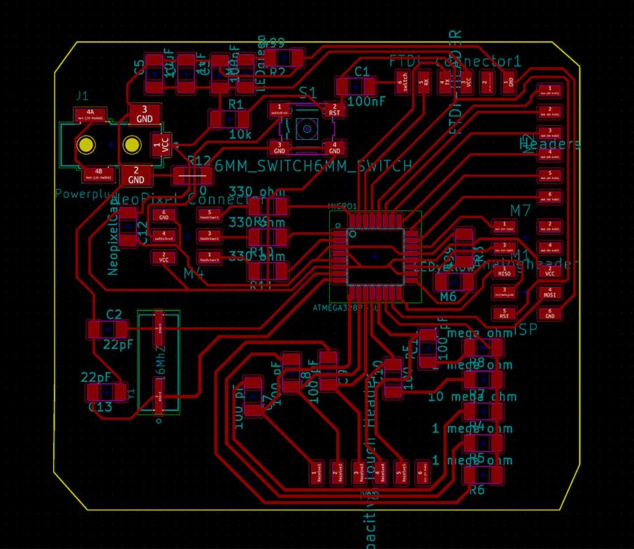 Final design of my Satsha Neopixel touch board
Power supply of my board
For my final project I will use an extern power supply. Because I will place it in my home, the best option is to use a wall power plug. I have an adapter that I will use that converts the 220 Volt to 5 Volt that I can use for my board.
- Satsha Kit: The Satsha Kit need a maximum of 5 Volt. I can use a DC converter to 5 Volt and 2.0 Amp. More information on the Satsha Kit github
- The Neopixels: Neopixels are described as “5 Volt devices”. So this will work with my plan to use 5 volt. Although some things should be taken into account, as mentioned on the gürü guide by Adafruit. Erik Katerborg has a nice cheat sheet that’s useful: Eerkmans Neopixel cheat sheet
- The Capacitive sensor: I used these tutorials: Arduino Capacitive Sensing Library by Paul Badger and the PJRC on Capacitive Sensor Library. This works on 5 Volt as well. They do mention that the capacitive can fluctuate due to difference in power supply. I can fine tune this in the code.
- The Movement: the movement of the leaves are kinetic, this means that they are not connected to the circuit and therefore don’t need power.
Milling and soldering my board
For my final project I went to the Makerslab to mill my board. They have a LPKF Protomat, it was broken for a while but it’s fixed and I wanted to try it out. Before I could work with this machine I had to convert my KiCAD files to Gerber files so I could used them in CircuitCAM and follow the documentation by Loes Bogers on LPKF Protomat and Eagle
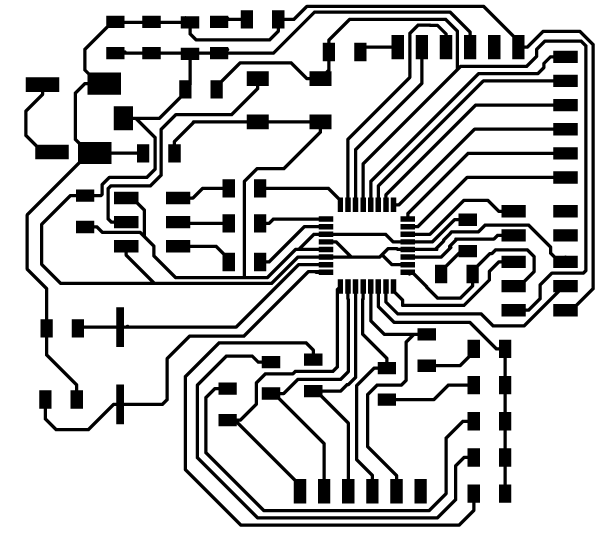 Traces of final design of my Satsha Neopixel touch board
Exporting Gerber files in KiCad
To mill with the Protomat, I first have to export Gerber files so I’m able to use Circuit Cam to prepare my files. So I looked at the tutorial by Sparkfun on exporting Gerbers from Kicad. It’s really easy. These are the steps I took:
Step 1: Go to File menu and select plot
First go to the plot menu that can be found under ‘file’
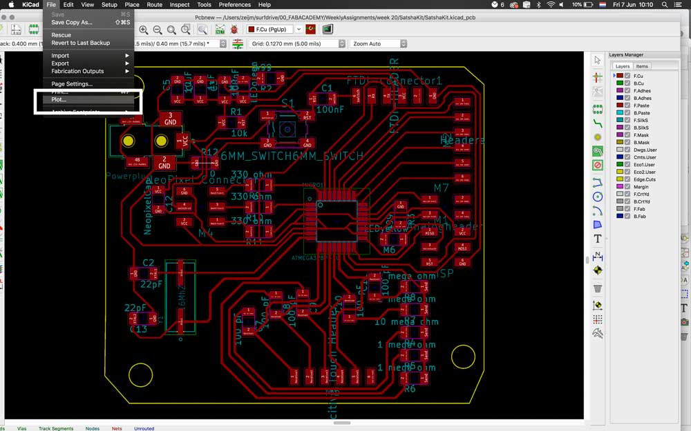 Go to File -> Plot
Step 2: Plot Gerber files
After this a pop-up opens. It’s important to set the right folder and relative path for your project. Double check that you’ve selected the right layers for you export. After this click on ‘Plot’, this will generate the different Gerber files you need for circuit cam.
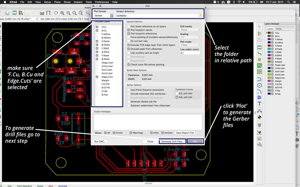 Select the right values and plot Gerber files
Step 3: Generate drill files
When needed you can also generate drill files in the export. Make sure you select the right setting and the right folder. Next step is to select: ‘Generate Drill File’ and that’s it. 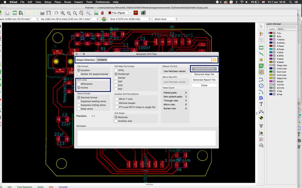 Go to File -> Plot
Using Circuit Cam and Protomat
As mentioned before Loes Bogers wrote a very well documented tutorial on the use of Protomat and preparing the file in circuit cam. I followed the steps in her tutorial: Documentation by Loes on LPKF Protomat
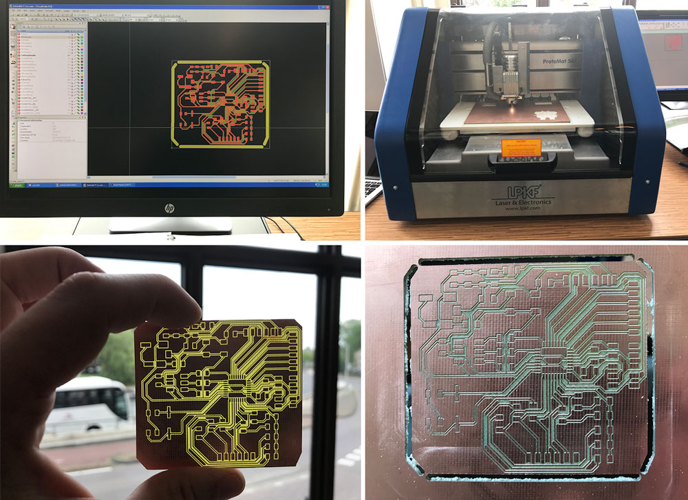 Milling my board with LPKF Protomat
The traces are really small, but it works. Next time I would like to see how I could make them a bit bigger.
Soldering my board.
When the milling was done I could solder my board. The soldering of the ATMega328P was really tricky. I soldered three pins together. However with patiences and a tweezer I managed to disconnect them.
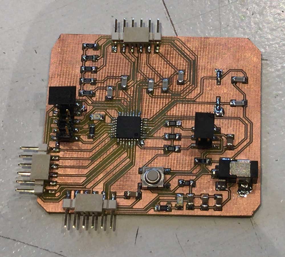 soldering my Satsha Kit
Step 4: Programming my board
First I had to burn the bootloader and I tested my board with some given example codes.
Burning bootloader and testing the board
For the programming of my board, I usedthe Satshakit tutorial. What was different than my previous boards was that I only needed the FabISP for the bootloader. I use the FTDI to upload my code.
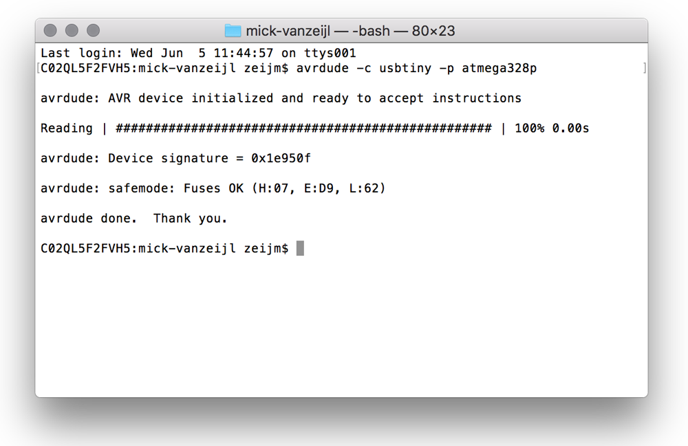 atmega 328p fuses ok
- First check if it could see the board, and the Fuses are ok.
avrdude -c usbtiny -p atmega328p - Second step was to Burn the Bootloader:
- open Arduino IDE
- select the USBtinyISP as programmer by clicking on Tools -> Programmer.
- select Arduino UNO as Tools -> Board
- click on Tools -> Burn Bootloader.
- This went fine, after burning the bootloader, I wanted to test if I could upload the Neopixel Strandtest.
- Make sure the wiring of the FDTI-cable is correct. My first tests gave the error: ‘User configuration file does not exist or is not a regular file, skipping’ -> it turned out I switched the tx and rx around.
- I uploaded the sketch and it worked. After this one I also used the capacitive touch test to see if this would work, and it did.
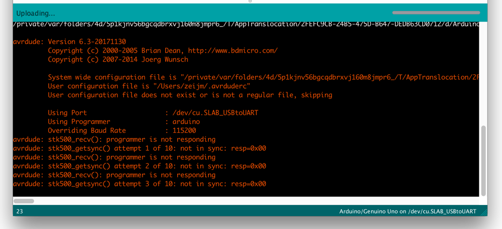 error uploading the sketch to the satshakit
Programming my board
These first steps went really fast so I in the end I left the programming till last because I knew this worked. However in the end I didn’t have enough time to make a nice code, the way I wanted for the final presentation.
The code I had during the final presentation was a proof of concept my project worked. What I did in the end was combining the two example codes I used before. So the Neopixel strandtest by Adafruit and the Capacitive Sensor code by Paul Badger.
//Based on the example sketches by Ada Fruit
// CapitiveSense Library Demo Sketch - Paul Badger 2008
// and Neopixel Strand test - A basic everyday NeoPixel strip test program by Adafruit
// Changed by Micky van Zeijl on June 17, 2019

#include <CapacitiveSensor.h>
#include <Adafruit_NeoPixel.h>

#define LED_PIN    3
#define LED_COUNT 4

Adafruit_NeoPixel strip(LED_COUNT, LED_PIN, NEO_GRB + NEO_KHZ800);

CapacitiveSensor   cs_10_8 = CapacitiveSensor(10, 8);       // 10M resistor between pins 4 & 2, pin 2 is sensor pin, add a wire and or foil if desired
CapacitiveSensor   cs_10_9 = CapacitiveSensor(10, 9);       // 10M resistor between pins 4 & 6, pin 6 is sensor pin, add a wire and or foil
// CapacitiveSensor   cs_10_7 = CapacitiveSensor(10,7);        // 10M resistor between pins 4 & 8, pin 8 is sensor pin, add a wire and or foil
// CapacitiveSensor   cs_10_6 = CapacitiveSensor(10,6);


void setup() {


  cs_10_8.set_CS_AutocaL_Millis(0xFFFFFFFF);     // turn off autocalibrate on channel 1 - just as an example
  Serial.begin(9600);

  strip.begin();           // INITIALIZE NeoPixel strip object (REQUIRED)
  strip.show();            // Turn OFF all pixels ASAP
  strip.setBrightness(50); // Set BRIGHTNESS to about 1/5 (max = 255)
}


void loop() {
long start = millis();
  long total1 =  cs_10_8.capacitiveSensor(30);
  long total2 =  cs_10_9.capacitiveSensor(30);


   Serial.print(millis() - start);        // check on performance in milliseconds
    Serial.print("\t");                    // tab character for debug windown spacing

    Serial.print(total1);                  // print sensor output 1
    Serial.print("\t");
    Serial.print(total2);                  // print sensor output 2
    Serial.print("\t");
    delay(10);


  if (total1 > 400) {

    strip.setPixelColor(1, 0, 252, 0);
    strip.setPixelColor(2, 124, 252, 0);
    strip.setPixelColor(3, 50, 252, 50);
    strip.setPixelColor(4, 0, 252, 0);


  }

   else if (total2 > 400) {
 greenRainbow(10);
  }

}


// Some functions of our own for creating animated effects -----------------

// Fill strip pixels one after another with a color. Strip is NOT cleared
// first; anything there will be covered pixel by pixel. Pass in color
// (as a single 'packed' 32-bit value, which you can get by calling
// strip.Color(red, green, blue) as shown in the loop() function above),
// and a delay time (in milliseconds) between pixels.
void colorWipe(uint32_t color, int wait) {
 for(int i=0; i<strip.numPixels(); i++) { // For each pixel in strip...
   strip.setPixelColor(i, color);         //  Set pixel's color (in RAM)
   strip.show();                          //  Update strip to match
   delay(wait);                           //  Pause for a moment
 }
}


// Rainbow cycle along green parts
void greenRainbow(int wait) {
  // Hue of first pixel runs 5 complete loops through the color wheel.
  // Color wheel has a range of 65536 but it's OK if we roll over, so
  // just count from 0 to 5*65536. Adding 256 to firstPixelHue each time
  // means we'll make 5*65536/256 = 1280 passes through this outer loop:
  for (long firstPixelHue = 65536/6; firstPixelHue < 10 * 65536; firstPixelHue += 124) {
    for (int i = 0; i < strip.numPixels(); i++) { // For each pixel in strip...
      // Offset pixel hue by an amount to make one full revolution of the
      // color wheel (range of 65536) along the length of the strip
      // (strip.numPixels() steps):
      int pixelHue = firstPixelHue + (i * 65536/2 / strip.numPixels());
      // strip.ColorHSV() can take 1 or 3 arguments: a hue (0 to 65535) or
      // optionally add saturation and value (brightness) (each 0 to 255).
      // Here we're using just the single-argument hue variant. The result
      // is passed through strip.gamma32() to provide 'truer' colors
      // before assigning to each pixel:
      strip.setPixelColor(i, strip.gamma32(strip.ColorHSV(pixelHue)));
    }
    strip.show(); // Update strip with new contents
    delay(wait);  // Pause for a moment
  }
}
With this code two of the four sensors work. One of them turns all the Neopixel to blue and the other one start the green rainbow cycle. However with this version I wasn’t able to turn off the lights, or switch cycles. In the end I changed this after the final presentation because I wanted to finish it more the way I had in my mind.
First I started with testing each part again. So could fine tune the capacitive touch.
capacitive touch test
//Based on the example sketches by Ada Fruit
// CapitiveSense Library Demo Sketch - Paul Badger 2008
// and Neopixel Strand test - A basic everyday NeoPixel strip test program by Adafruit
// Changed by Micky van Zeijl on June 29, 2019

#include <CapacitiveSensor.h>
#include <Adafruit_NeoPixel.h>
#define LED_PIN   3
#define LED_COUNT 4

Adafruit_NeoPixel strip(LED_COUNT, LED_PIN, NEO_GRB + NEO_KHZ800);

CapacitiveSensor   cs_10_7 = CapacitiveSensor(10, 7);       // 1M resistor
CapacitiveSensor   cs_10_9 = CapacitiveSensor(10, 9);       // 1M resistor
CapacitiveSensor   cs_10_6 = CapacitiveSensor(10, 6);       // 1M resistor
CapacitiveSensor   cs_10_5 = CapacitiveSensor(10, 5);       // 10M resistor


void setup()
{
  cs_10_7.set_CS_AutocaL_Millis(0xFFFFFFFF);     // turn off autocalibrate on channel 1 - just as an example
  Serial.begin(9600);

  strip.begin();           // INITIALIZE NeoPixel strip object (REQUIRED)
  strip.show();            // Turn OFF all pixels ASAP
  strip.setBrightness(50); // Set BRIGHTNESS to about 1/5 (max = 255)
}

void loop() {
  long start = millis();
  // arbitrary delay to limit data to serial port

  if (isEffectEnabled(1)) {
    Effect1(strip.Color(0, 255, 0), 0);
    //delay (10);
  }

  else if (isEffectEnabled(2)) {
    Effect2(strip.Color(0, 0, 255), 0);
    //delay (10);
  }

  else if (isEffectEnabled(3)) {
    Effect3(0);
  }

  else if (isEffectEnabled(4)) {
    Effect4(strip.Color(0, 0, 0), 0);
    //delay (10);
  }


}

bool isEffectEnabled (int NR) {
  long total1 =  cs_10_5.capacitiveSensor(30);
  long total2 =  cs_10_6.capacitiveSensor(30);
  long total3 =  cs_10_7.capacitiveSensor(30);
  long total4 =  cs_10_9.capacitiveSensor(30);

  //Serial.print(millis() - start);        // check on performance in milliseconds
  //Serial.print("\t");                    // tab character for debug windown spacing
/*
  Serial.print(total1);                  // print sensor output 1
  Serial.print("\t");
  Serial.print(total2);                  // print sensor output 2
  Serial.print("\t");
  Serial.print(total3);                // print sensor output 3
  Serial.print("\t");
  Serial.println(total4);                // print sensor output 4
  Serial.print("\t");
  //delay(10);
  */

  if (total1 > 800 && NR == 1) {
    return true;
  }

  if (total2 > 400 && NR == 2) {
    return true;
  }

  else if (total3 > 400 && NR == 3) {
    return true;
  }
  else if (total4 > 400 && NR == 4) {
    return true;
  }

  return false;

}

void Effect1(uint32_t color, int wait) {
  for (int i = 0; i < strip.numPixels(); i++) { // For each pixel in strip...
    if (!isEffectEnabled(1)) {
      break;
    }
    strip.setPixelColor(i, color);         //  Set pixel's color (in RAM)
    strip.show();                          //  Update strip to match
    delay(wait);                           //  Pause for a moment
  }
}


void Effect2(uint32_t color, int wait) {
  for (int i = 0; i < strip.numPixels(); i++) { // For each pixel in strip...
    if (!isEffectEnabled(2)) {
      break;
    }
    strip.setPixelColor(i, color);         //  Set pixel's color (in RAM)
    strip.show();                          //  Update strip to match
    delay(wait);                           //  Pause for a moment
  }
}

/* Rainbow cycle along green parts
void Effect3(int wait) {
  for (long firstPixelHue = 65536/6; firstPixelHue < 10 * 65536; firstPixelHue += 124) {
      if (!isEffectEnabled(3)) {
        break;
      }
    for (int i = 0; i < strip.numPixels(); i++) { // For each pixel in strip...
      int pixelHue = firstPixelHue + (i * 65536/2 / strip.numPixels());
      strip.setPixelColor(i, strip.gamma32(strip.ColorHSV(pixelHue)));
    }
    strip.show(); // Update strip with new contents
    delay(wait);  // Pause for a moment
  }
}
*/

void Effect3(int wait) {
  // Hue of first pixel runs 5 complete loops through the color wheel.
  // Color wheel has a range of 65536 but it's OK if we roll over, so
  // just count from 0 to 5*65536. Adding 256 to firstPixelHue each time
  // means we'll make 5*65536/256 = 1280 passes through this outer loop:
  for(long firstPixelHue = 0; firstPixelHue < 5*65536; firstPixelHue += 256) {
   if (!isEffectEnabled(3)) {
       break;
      }
    for(int i=0; i<strip.numPixels(); i++) { // For each pixel in strip...
      // Offset pixel hue by an amount to make one full revolution of the
      // color wheel (range of 65536) along the length of the strip
      // (strip.numPixels() steps):
      int pixelHue = firstPixelHue + (i * 65536L / strip.numPixels());
      // strip.ColorHSV() can take 1 or 3 arguments: a hue (0 to 65535) or
      // optionally add saturation and value (brightness) (each 0 to 255).
      // Here we're using just the single-argument hue variant. The result
      // is passed through strip.gamma32() to provide 'truer' colors
      // before assigning to each pixel:
      strip.setPixelColor(i, strip.gamma32(strip.ColorHSV(pixelHue)));
    }
    strip.show(); // Update strip with new contents
    delay(wait);  // Pause for a moment
  }
}


void Effect4(uint32_t color, int wait) {
  for (int i = 0; i < strip.numPixels(); i++) { // For each pixel in strip...
   // if (!isEffectEnabled(4)) {
    //  break;
   // }
    strip.setPixelColor(i, color);         //  Set pixel's color (in RAM)
    strip.show();                          //  Update strip to match
    delay(wait);                           //  Pause for a moment
  }
}
What I did:
- I added an boolean function that keeps track if the sensor is touched
- For each effect I added this boolean in the for loop, so it would always check if it could continue.
Before I connected my board to my final project I first tested it with four Neopixels.
capacitive touch test with Neopixels
This works. Now I can give the Neopixels three different effects and I’m able to stop them even when they’re in a loop. There still is a lag or a delay that makes the response slow. This would be something to fine tune.
Step 5: Connecting the Neopixels
he optic fibers are the most important part of my project because these create the poetic atmosphere I want to use to recreate the feeling of laying under a tree at night. To make sure the Neopixels work nicely with the optic fibers I needed to design a connecting part. I first did a test run. I used additive design for this part because it’s really specific for my final project.
![]() Bottom of Neopixel connector
Bottom of Neopixel connector
- I used the Neopixel LED-strip because these are mounted on flexible material and they already have a capacitor mounted on the strip. I can bend these in such a way that the Neopixel sticks out.
- I made a bottom base for the Neopixel, that can be clicked onto the optic fiber connector.
- The optic fiber connector connects the fibers to the Neopixel. it makes sure the fibers can’t move and are placed straight onto the light of the Neopixel.
Step 6: Designing and making the leaf connector
To be able to connect the leaves, with the Neopixel connector and the base I needed an object in between. I write more about it on the final project page. The basic requirements I for these parts were:
- There should be a solid connection between Neopixel and Optic Fibers
- There should be room for wiring
- It should be hold the leaf construction
- It should be able the create movement.
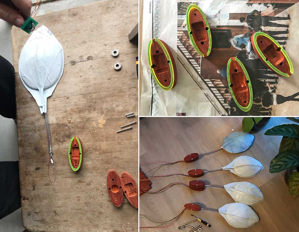
testing possible movement and size for leaf connector
I did a lot of tests with springs and movement as you can see on top of this page. Based on my final test I decided I will leave the springs for now. And I decided that the dimensions of the connector should be 10 cm in length and 4 cm wide. Finally the height was partly decided by the dimensions of my wood. The patoek wood was 2 cm in height. I needed three layers.
- top layer: need to fit on top of the middle layer with the placement of the Neopixel-connector, the optic fibers and the brass rod.
- Middle layer: needs a pocket for the placement of the NEOpixel-connector, it need place for the optic fibers and the brass rod to hold them in place, and it need a hole for wiring.
- Bottom layer: needs a connection to the bearing for movement, and a hole for the wires.
 Leaf connector
Step 7: Designing the Base
I had a lot of trouble with the base. First of all because during the full Fab Academy I had a much more organic design in my mind. However ones the Wildcard week and composites didn’t turn out the way I wanted, I had to think of something else. Due to time I decided I would create a more abstract trunk kind of idea, which would include the leaves.
More details on the design and production of the base can be found in my documentation on the final project.
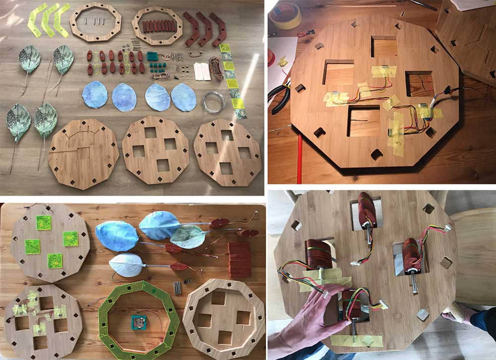
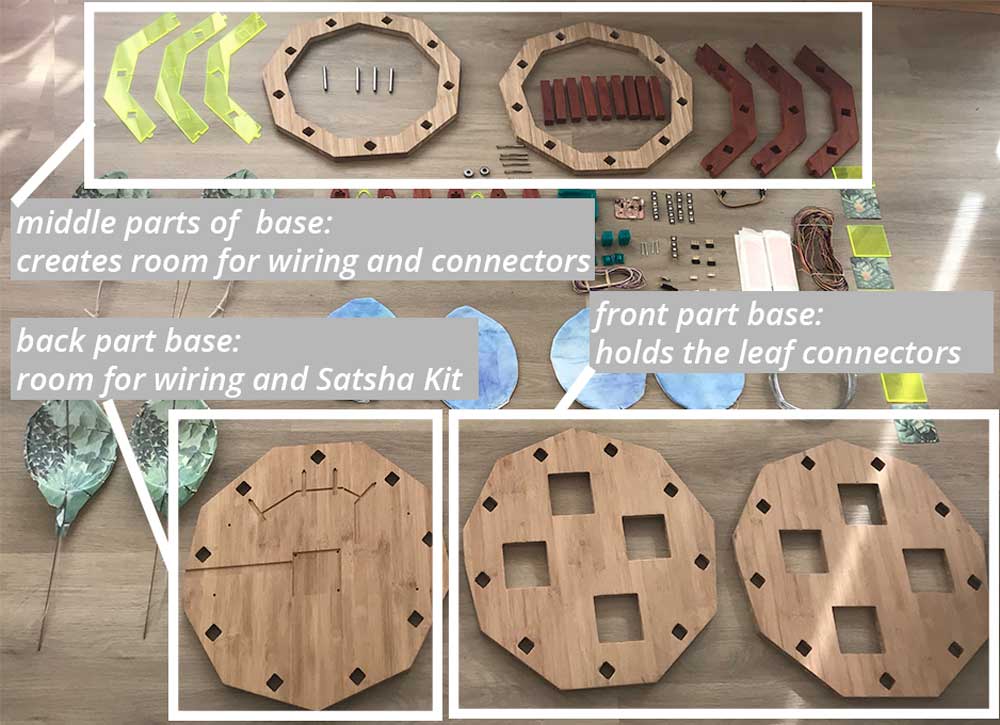 Parts of the base
I had to fine tune a lot of the work done by the Shopbot as lines were not straight and circles weren’t round, even though they definitely were in my design, I triple checked. This costs me a lot of extra time. In the end I managed. Although for a next iteration I would go back to a more organic form.
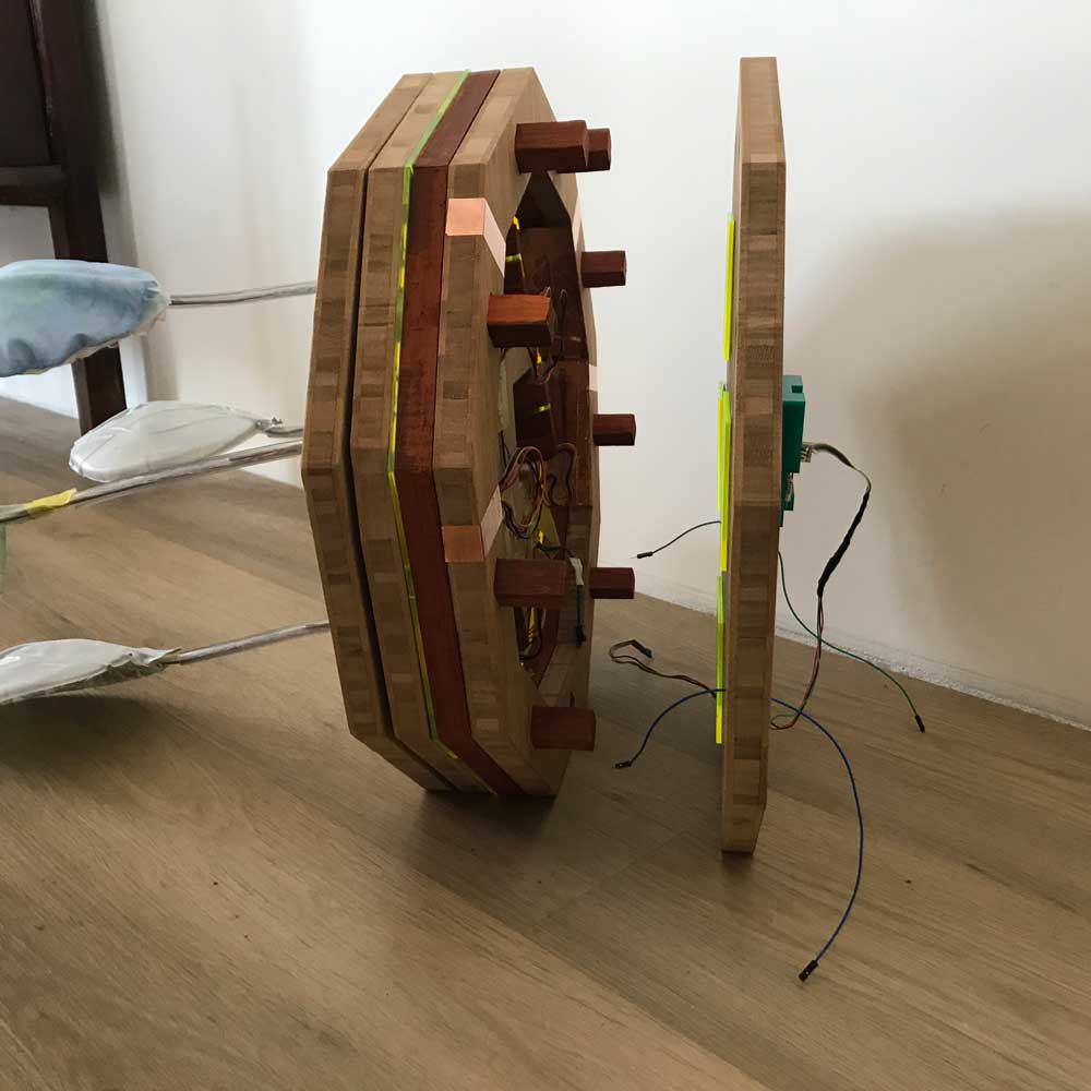 Base of my final project
Step 8: Assembling all the parts.
When all the parts were finished, it was time to assemble everything together in one final project. This took a lot longer than I thought and planned.
 Assembling parts
More details about the assembling and final result of my final project can be found on the final project page.
 Assembling parts
What I did wrong – and how I solved it
The biggest part that went wrong was my planning. I had a very good idea about the time management but the design I had in mind didn’t fit the planning. It was too complex with too many different parts. I solved it by working really hard and withs some extra help from Klaas-jan. For next time I will think twice to realize what I could make smaller, less complex, and to make sure it fits in the time I have. Although during the whole of the Fab Academy I noticed that it’s really difficult to get a good idea of the time and complexity of ideas when you’re not experienced.
In the documentation of my final project I describe all the parts that I would change or do differently next time.
What I learned
Time management
Most important lesson for me regarding time management is ‘kill your darlings’, I already know this important, but it’s difficult to do. I should have made the design of my final project a lot simpler with less different parts.
A lot!
Overall I learned a lot during all the weeks of the Fab Academy. I started as a beginner with no experience with almost all tools and techniques. Now I managed to design, make and produce a product that shows all the techniques, tools and machines learned, which are a lot.
What made me proud!
I’m most proud of my connector and the electronics. I’m also proud that I made all the parts myself. And most important of all that it works!
Credits and references
This is a reference list to all the people and works cited. In the documentation of my final project I thank all the people who helped and supported me during the Fab Academy.
Refereces
Xu, H., Knoop, E., Coros, S., & Bächer, M. (2018). Bend-it: design and fabrication of kinetic wire characters. ACM Transactions on Graphics, 37(6), 1–15. https://doi.org/10.1145/3272127.3275089
Images used
Images in the overview of painting by Piet Mondriaan
- Piet Mondriaan, ‘Bloeiende bomen’, 1902-05 or 1916-18. Gemeentemuseum, Den Haag
- Piet Mondriaan, ‘Polder Landscape with Silhouetted Young Tree’, 1900–01 (detail). Private collection, London
- Piet Mondriaan, ‘Willow grove: impression of light and shadow’, 1904-06. Dallas Museum of Art, Dallas (Texas)
- Piet Mondriaan, ‘Avond; De Rode Boom’, 1908-10. Gemeentemuseum, Den Haag
- Piet Mondriaan, ‘De grijze boom’, 1911. Gemeentemuseum, Den Haag
- Piet Mondriaan, ‘Flowering Apple Tree’, 1912. Gemeentemuseum, Den Haag
- Piet Mondriaan, ‘Compositie bomen 2’, 1912-13. Gemeentemuseum, Den Haag
- Piet Mondriaan, ‘Compositie 2’, 1913. Kröller-Müller Museum, Otterlo