During this input devices week I wanted to make an input device that I could use in my final project. I decided to make a touch slider to use as a control button in the final project. It could for example change the type of feedback the installation would give.
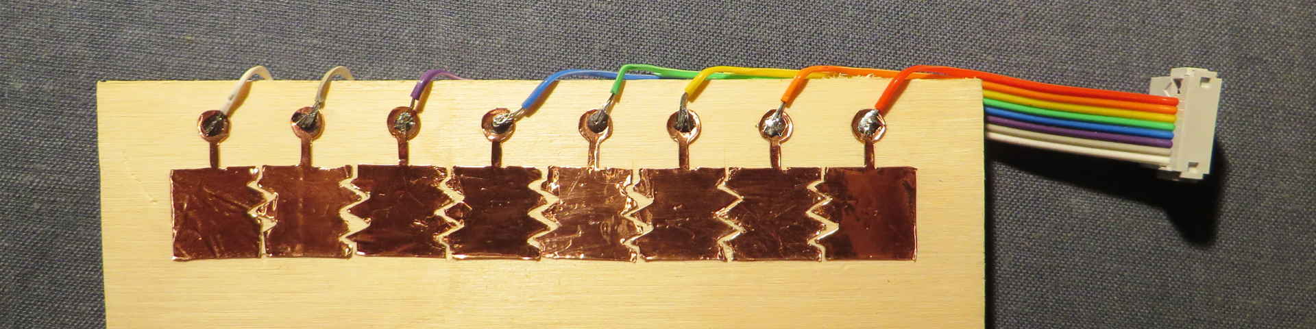
The touch slider is using copper that change in capacitive behaviour when you touch them. As you slide over the different pads, the microcontroller can read on what pad your finger is.
measure something: add a sensor to a microcontroller board that you've designed and read it
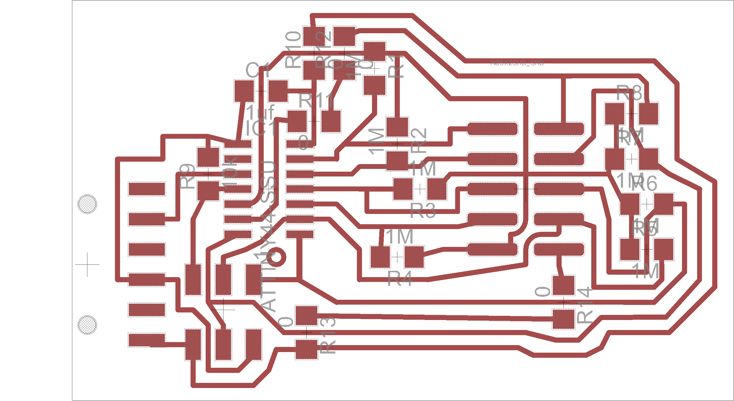
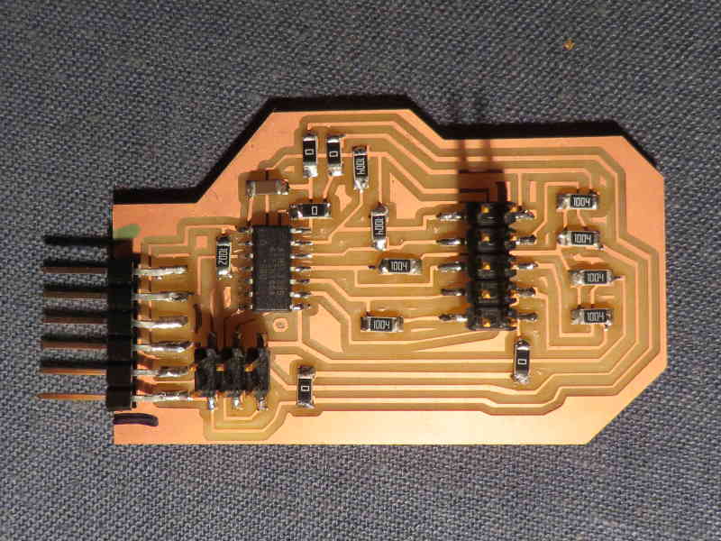
I did some research on earlier Fab Academy/How to make (almost) anything assignments during the input week and found a few good examples. I based my board design on the work of Akash Badshah. I've redrawn the board from scratch in Eagle, because I never did this and wanted to see how it works. I didn't want te copper touch pads to be on the board. Instead I used to vinyl cutter to make the copper pad. To be able to connect the copper pads to the board and easily change between different layouts, I added a 10 pin header.
eagle files of my board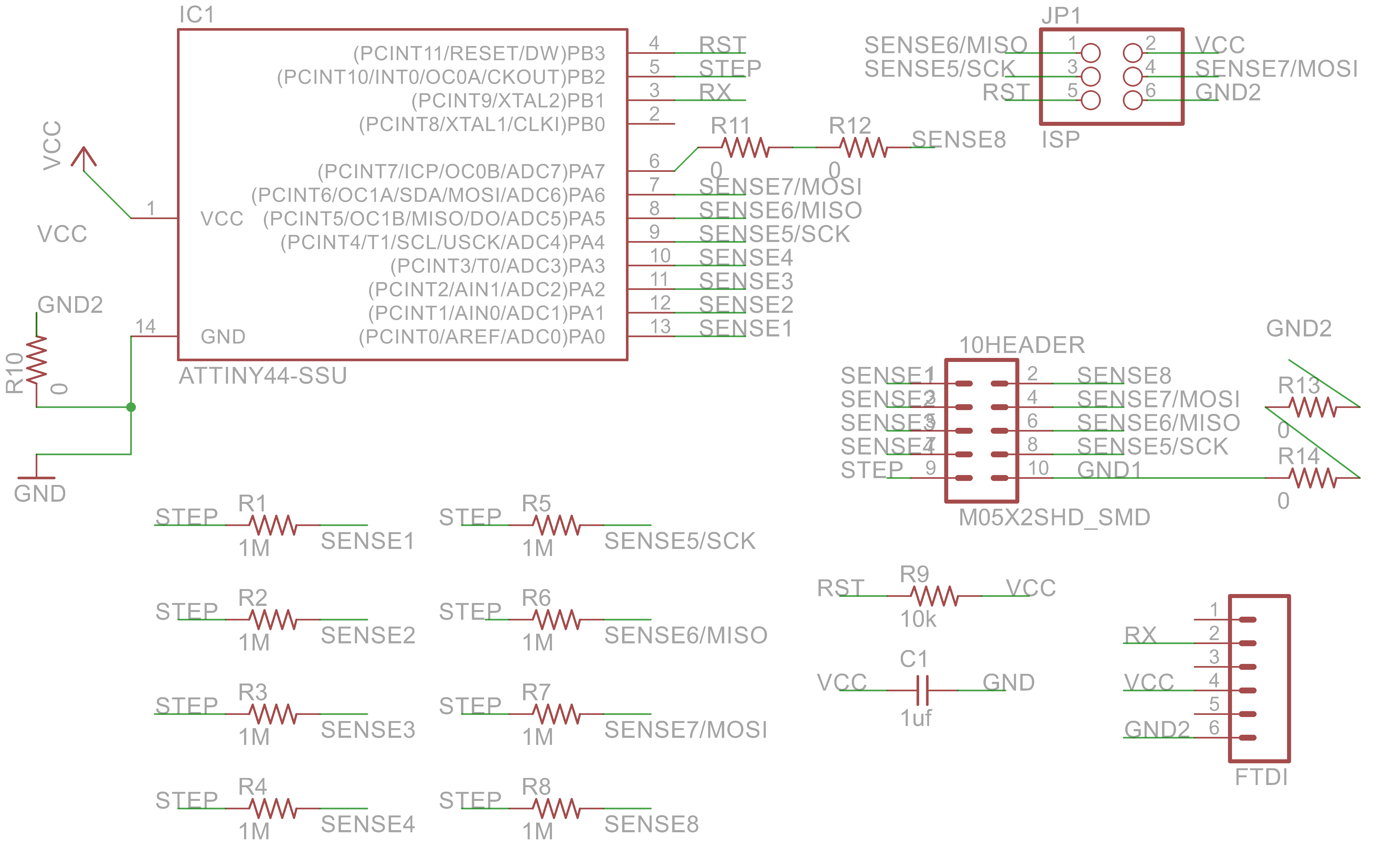
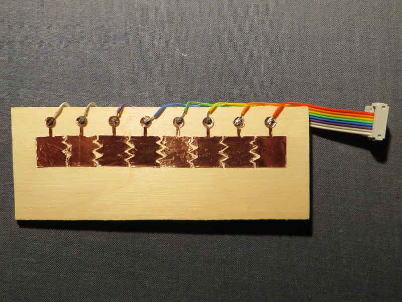
I made the pads from copper foil using the vinyl cutter. They didn't come out as clean as I wanted them to. There are a lot of sharp corners in my design which were hard to cut. The copper came loose and corners folded. In the end I had to manually trim the edges between most of the pads, only a few came out clean. The next time I would limit the straight corners in my design. I've also heard it might help to send open curves, in stead of closed curves, so the vinyl cutter can cut a sharp corner in two lines, instead of one, so it doesn't have to drag the knife around the corner.
UPDATE: during Week 14 of Fab Academy I had more succes with the vinyl cutter and updated the design of the pads

I could use Akash' code written in C to test the board, because of the similar schematic. The order of my pads was different, so had to change the definition of the pins to match with the measuring.
I also had to do some readjusting to find the right threshold. It's still not perfect, because it react differently to other people's fingers (which is also quite funny I think, but hard to debug). I got it working for my own finger as you can see in the video below, as my finger slides across the pads, the value increases.
code
The output you see on the screen is a value between 0 and 80. Left is 0, right 80 and as my finger slides along the pads, the value changes. When you touch two adjacent pads, it is shown in the output on the screen. For example, if pad 3 gives as output 30 and pad 4 give 40, the output when you touch pad 3 and 4 is 35.