This week I made an application that interfaces with the capacitive touch board I made in the input devices week. I made a rgb- color mixer that can be controlled by touch pads, connected to my laptop with an ftdi-cable.
write an application that interfaces with an input and/or output device
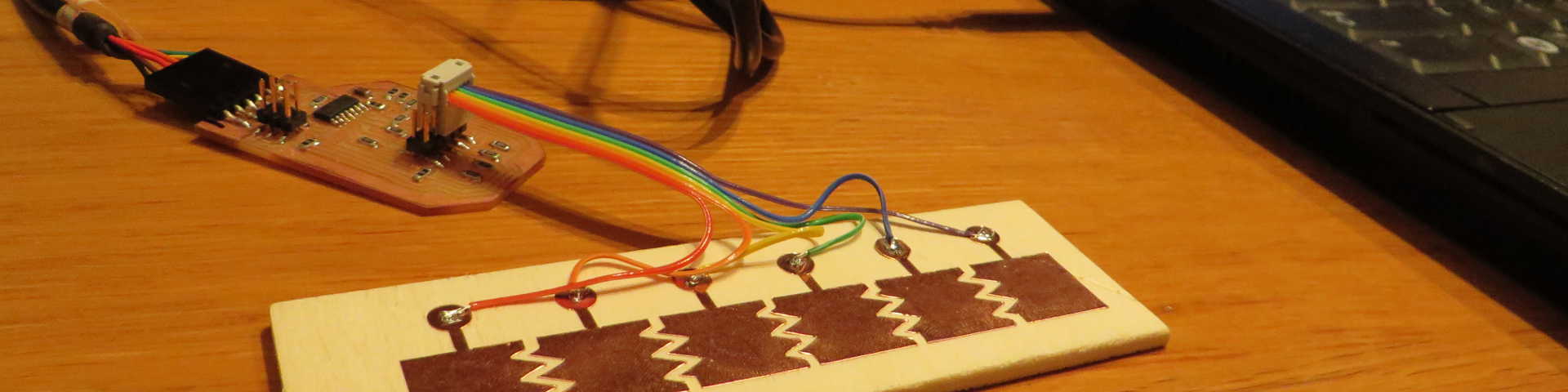
The first step was to reprogram the board from the input device week and change the serial output. During the input devices week the board was programmed to send a value between 0 and 80 to the serial monitor. Besides a value on one of the 8 pads (for example 10 for pad 1), it also give a value when a finger is on two pads (for example 15 for pad 1 and 2).

For this week's assignment I reduced the amount of pads from to 8 to 6. Also I've reprogrammed the board to only send the number of the pad the finger is on and not values half way. If a finger is on two pads, it will now just give both the numbers of the pads.
vector file pads
I wanted to do the programming for the application in javascript to learn more about web-based application. After doing some tutorials on javascript and nodejs, I got the serial port running in the nodejs environment. I wanted to use the stream from the serial communication in an html page, but did not manage to do this.
The tutorials and starting with javascript and nodejs took quite some time and because I only had a little time left, I decided to make a sketch continue in Processing.
Processing is pretty easy to use once you've used arduino and are a bit familiar with C code. When a finger touches one of the pads, the boards sends the number of the pad to the serial monitor. There are six pads, so the numbers I get on the serial monitor are 1, 2, 3, 4, 5 and 6. I made a sketch which reads from those serial communication and each of these numbers makes a different change to the RGB-color of the background. 1 increases the red-value, 2 increases the green value and 3 increases the blue value, so by touching these pads, the background gets brighter. 4, 5 and 6 decrease the values of red, green and blue, so the background gets darker. The rgb values are defined in a range between 0 and 50.
The serial output in my board is a char-value, but in my sketch it is read as an int-value. So I had to translate the value from int-values to char-values in the code, 1=49, 2=50, 3=51, 4=52, 5=53 and 6=54. It would be a bit neater to adjust this in the code, but it doesn't matter for the working of this sketch.
           // color mixer by Frank Vloet

import processing.serial.*;
int r = 0;
int g = 0;
int b = 0;
int max = 50;

Serial myPort;  // The serial port:

void setup() {
  // Open the port you are using at the rate you want:
  myPort = new Serial(this, "/dev/ttyUSB0", 9600);
  size(500, 500);

  colorMode(RGB, max);
  noStroke();
  background(r, g, b);

}

void draw() {
  while (myPort.available() > 0) {
    int inByte = myPort.read();
    //49 is int value of char 1
    //50 for 2
    //51 for 3 etc.

    //subtract blue
      if (inByte == 49) {
           if (b > 0){
           b = b - 1;
           background(r, g, b);
           }
        }
    //subtract green
      if (inByte == 50) {
           if (g > 0){
           g = g - 1;
           background(r, g, b);
           }
        }
    //subtract red
      if (inByte == 51) {
          if (r > 0){
           r = r - 1;
           background(r, g, b);
           }
        }
    //add blue
      if (inByte == 52) {
         if (b < max){
           b = b + 1;
           background(r, g, b);
           }
        }
    //add green
      if (inByte == 53) {
        if (g < max){
           g = g + 1;
           background(r, g, b);
           }
        }
    //add red
      if (inByte == 54) {
        if (r < max){
           r = r + 1;
           background(r, g, b);
           }
        }

  }
}