
Computer-Controlled Cutting
This week, there is a group assignment and an individual one. They are in general related to the usage of computerized cutting machines like laser cutters and vinyl cutters:
The group assignment:
- characterize your laser cutter's focus, power, speed, rate, kerf, and joint clearance.
-
Document your work to the group work page and reflect on your individual page what you learned.
- Design, laser cut, and document a parametric press-fit construction kit, which can be assembled in multiple ways. Account for the laser cutter kerf.
-
Cut something on the vinyl cutter.
Group assignment:
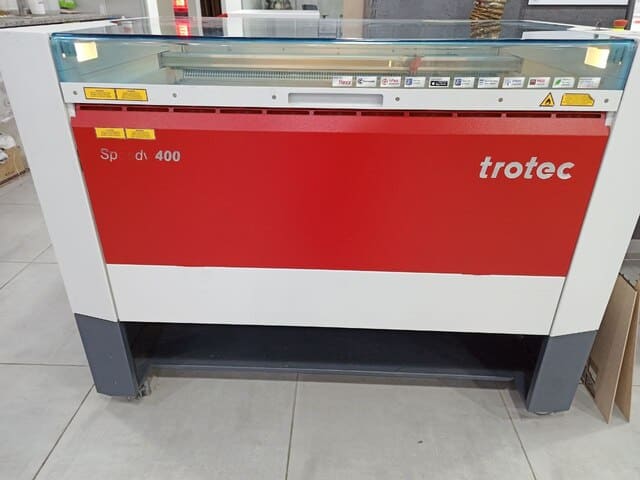
First, and before starting the cut operations, we had to know what the machine we will use and how to safely could be operated, so There are different types of laser cutters; one of them is the Trotec speedy 400 engraver, which we got here in TechWorks.
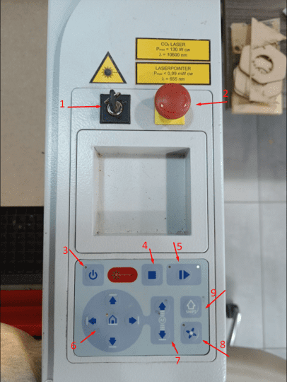
Trotec comes with clear controlling buttons.
- 1: Switch on-off.
- 2: Emergency push button.
- 3: Power on-off.
- 4: Stop cutting.
- 5: Pause cutting.
- 6: Moving laser head buttons.
- 7: Moving the bed of the machine up or down.
- 8: Vacuum on or off.
-
9: Used to speed the movement of laser head.
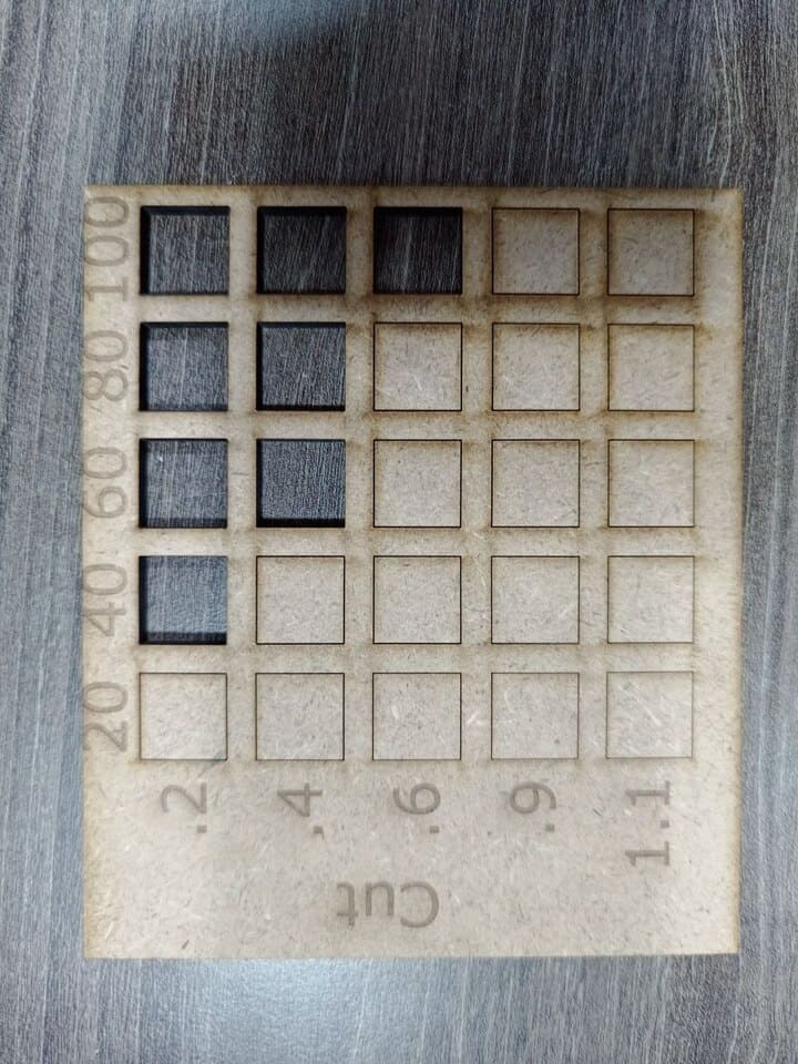
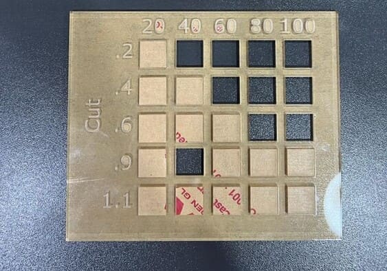
To characterize the laser cutting machine, we had to cut cut,engrave tests on different materials with addition to kerf and joints test, so first to start the cut test we made the design below on fusion 360 then prepare it on inkscape:
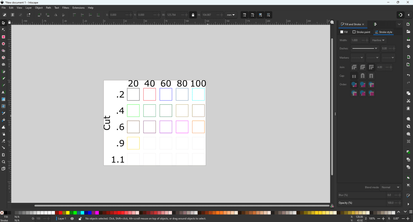
For mdf board with thickness 4.3mm we used different colors with different power and speed as shown below:
After cutting, we measured the rectangles width and height, and we found that the best value for cutting mdf 4.3mm thickness are P:100, V:60 since it's more accurate compared with other rectangles and operated with full machine capacity and maximum valid speed:
We did the same process for acrylic 3mm thickness, we noticed that at 0.9 speed when power 40 the cut was all the way through, but at the same speed and power 60, the cut was not through, and that was making no sense:
We checked the values of the power and by mistake the power instead of being a 40 it was 100, so we repeated the cut at power:40 and power:60 both with the same speed:0.9 and the cut was not through:

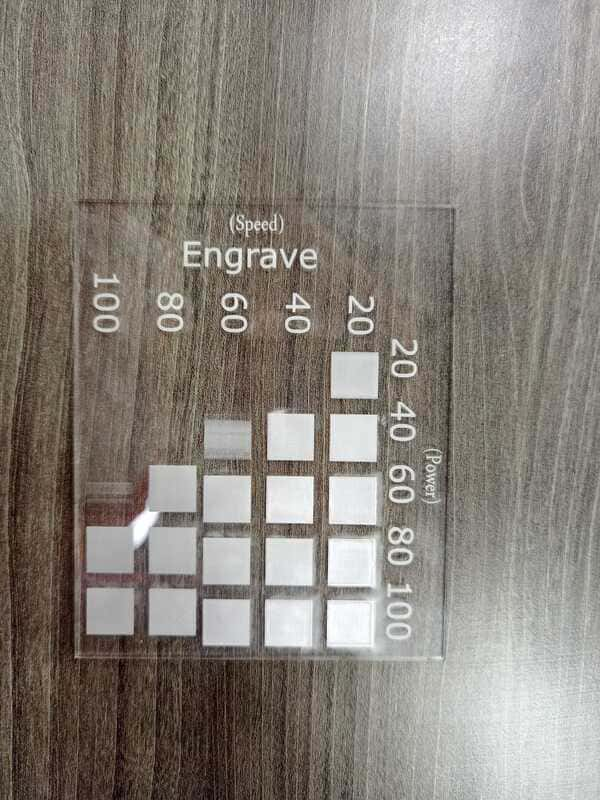
To start the engrave tests, we used the same shape but with fill colors, since to engrave parts we should use colors as fill not stroke:
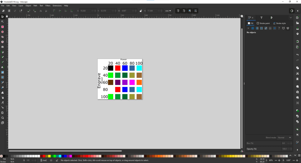
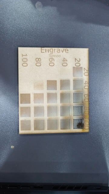
For the first engrave test, we used mdf with 4.3mm thickness, and after the machine fished engraving, we compromised between power,speed and the visual factor and we conclude that the best engrave values were with P:100,V:80 :
The second engrave test is with acrylic 3mm, using the same power amd speeds as mdf, the best values were P:100,V:100 :
To calculate the kerf for mdf 4.3mm, we made a big rectangle with 100mm width, and divided it into ten small rectangles, and the result was:
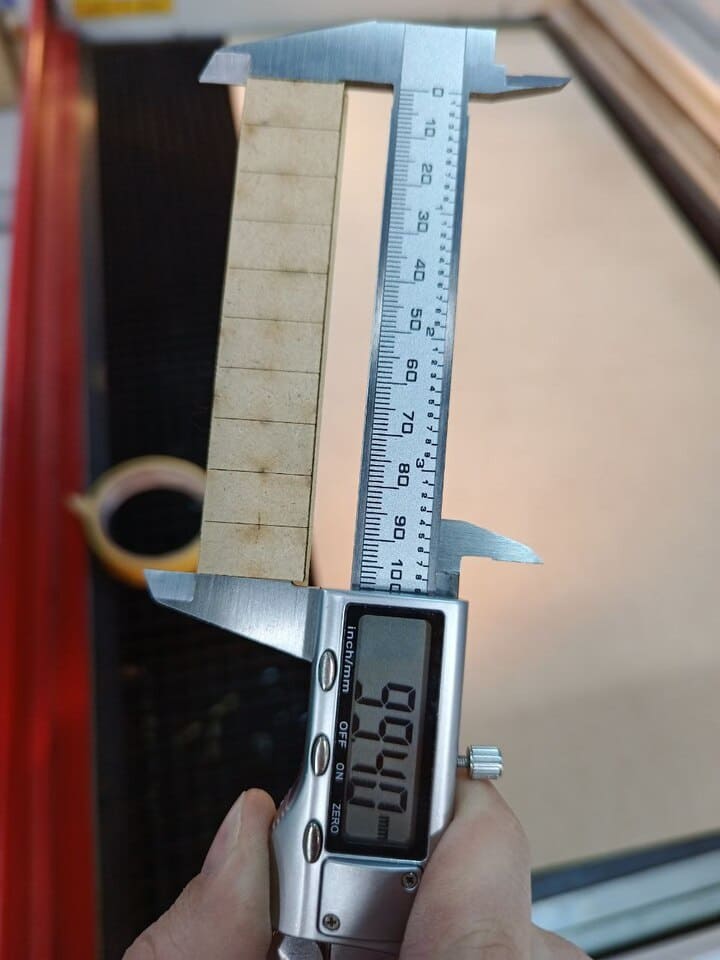
The kerf could be found by this equation:
Kerf = ( 100 - 99.4 ) / (11) = 0.055
To calculate the kerf of acrylic 3mm, following the same procedure:
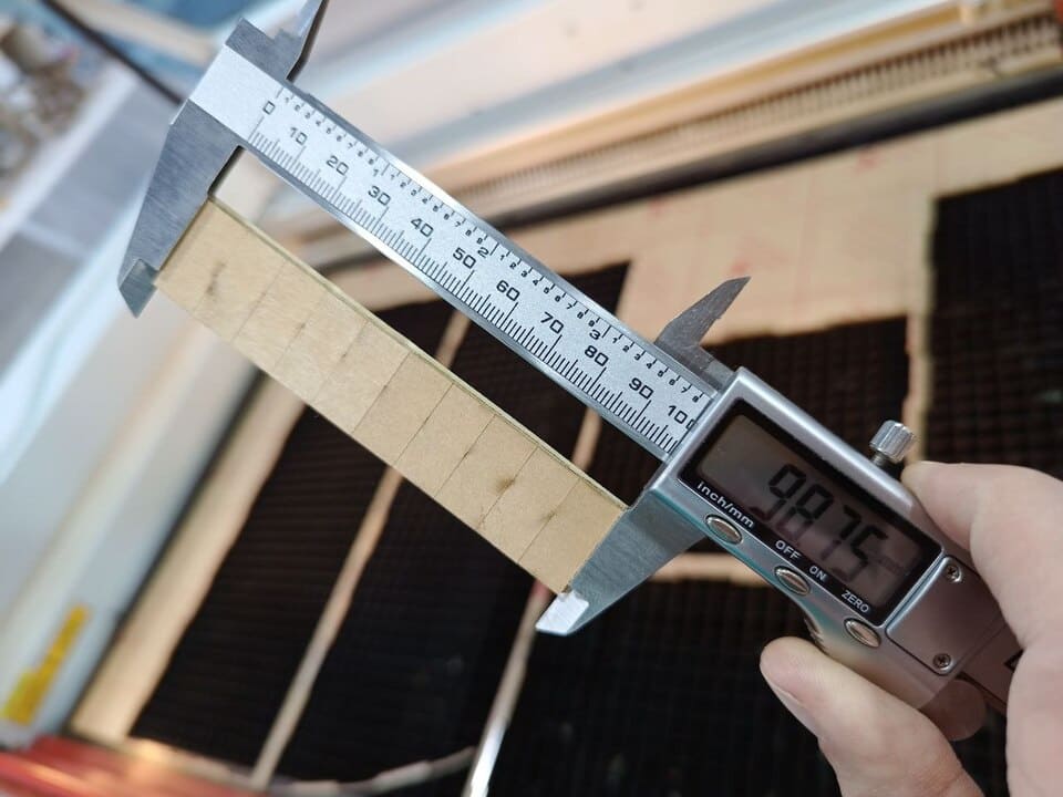
Kerf = ( 100 - 98.75 ) / (11) = 0.114
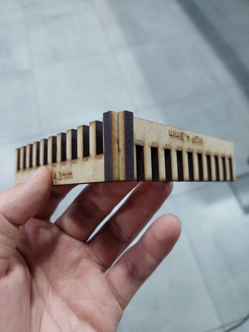
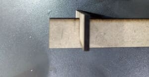
Final test is the joint test for mdf 4.3mm and acrylic 3mm, and starting with mdf the best joint thickness was 4.35 mm :
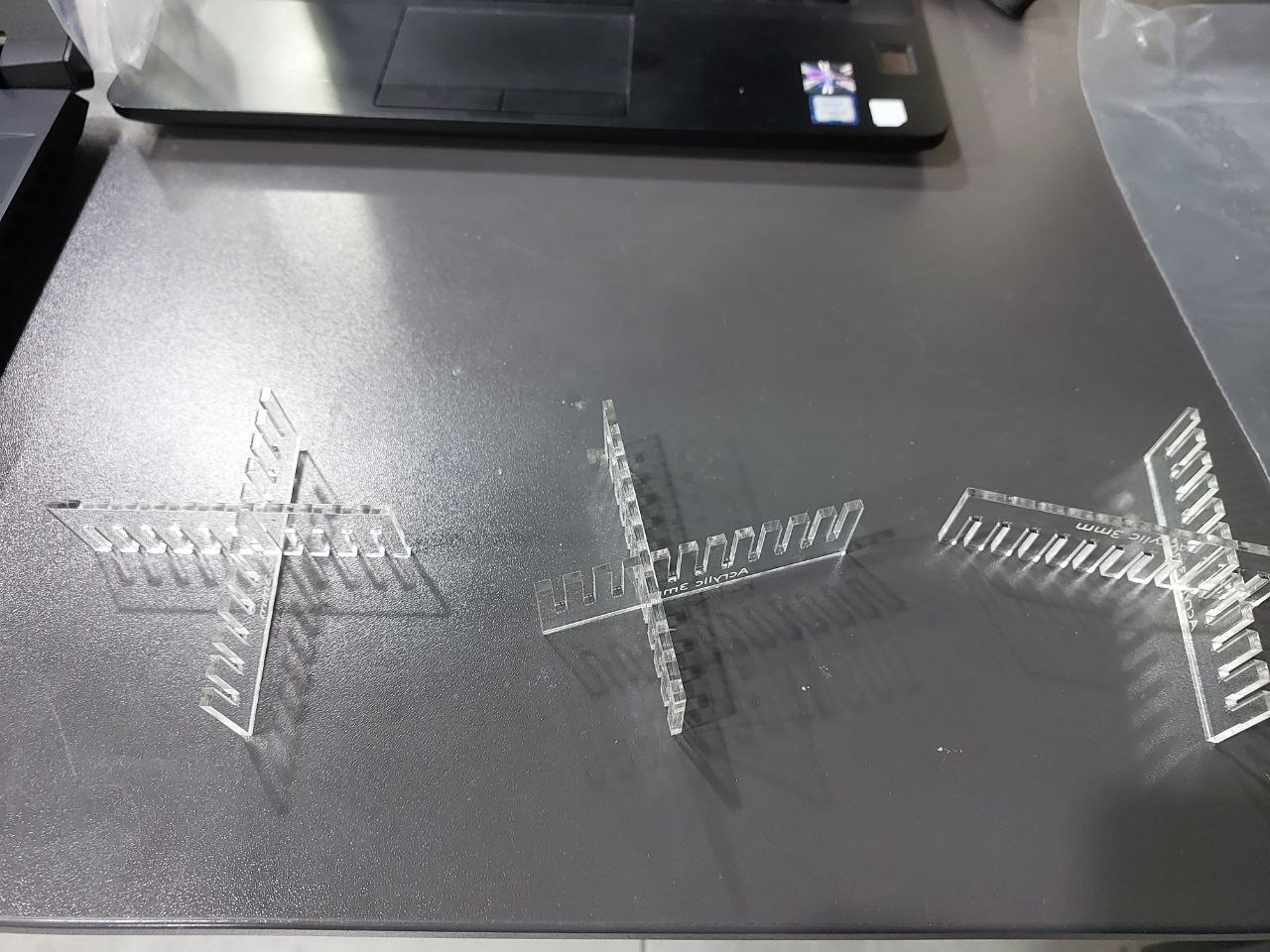
For acrylic, first, we tried to cut with a range of 2.95-3.05 mm, which did not work. The joints were loose since the kerf value for MDF was smaller than acrylic, so we tried the second test with a range of 2.8-2.9 mm, and it worked actually, but unfortunately, when we removed the acrylic sticker, the joint was loose a bit, so we did the final test with range 2.7-2.8, and finally, the best joint thickness value was 2.74mm as shown below (from right to left):
Individual assignment:
Starting with making a parametric modular kit to cut with mdf 4.3mm, I designed the parametric shapes using Fusion 360. I have started to add parameters to use while sketching.
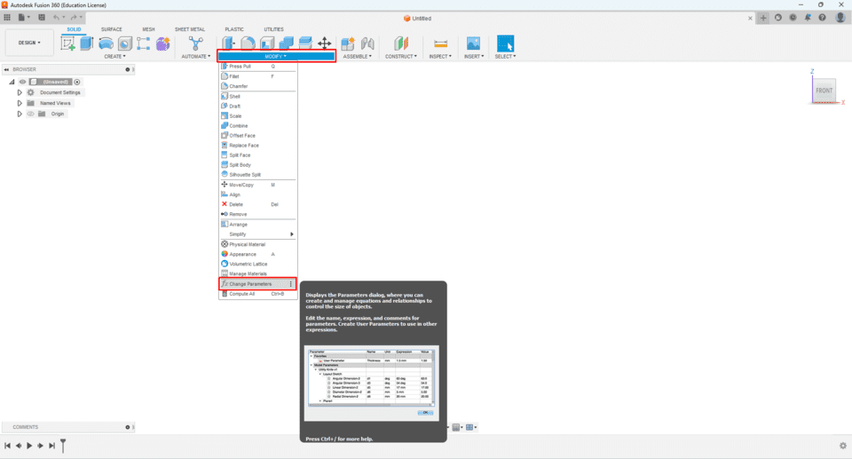
To add the parameters, from the modify list, then change parameter:
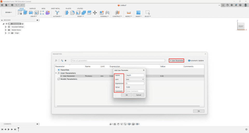
Now from the “+ user parameter,” I have added the name of the parameter, unit, expression, or the value of the parameter, and I have added some comments to make parameters easy to be remembered:
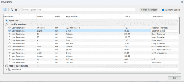
I made the thickness of the design, joints size, and the circle diameter of the gears, kerf value all are parametric so I can adjust them later on, and the picture below shows all the parameters:
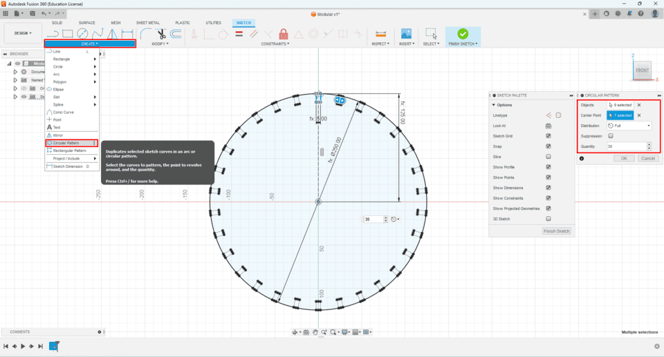
I sketched the first circle, and I used a great tool, a circular pattern, which helped me to make the same female joints around the circle by selecting the shape, then selecting the rotation center, which is the center of the circle, and for sure the quantity or numbers of shapes:
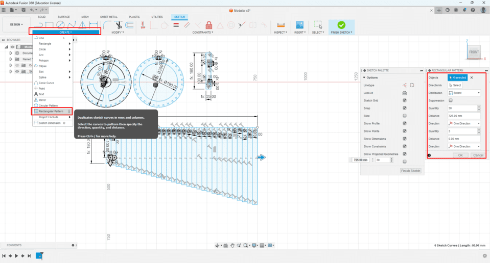
After that, I sketched the supports, and also, I used the rectangular pattern by selecting the object, then adding the number of elements and the direction of the pattern; in addition to choosing either the distance between the objects, which is spacing or distributing the elements evenly at a specified length it is really helpful and saves much time:
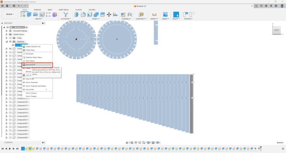
To make the sketch ready for laser cutting, I had to save it as .DXF format so that I could prepare the sketch with the right settings. I went to the sketch, right-clicked on the mouse, selected save as DXF, and chose the location to save it:
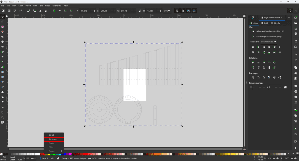
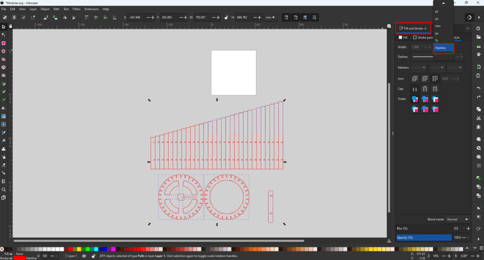
Now to prepare the file, I opened it using Inkscape; the stroke lines color is black, and since the laser cutting machine uses the color code, and red usually means cut, I converted the color to red, selected the lines, and right click on the red color from the bottom:
It was important to have an accurate cut, to make the stroke width as Hairline:
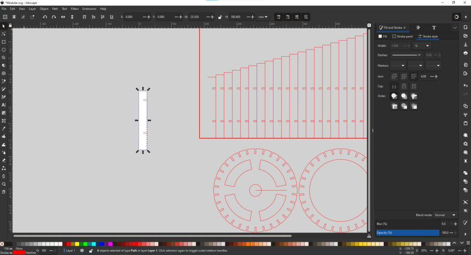
But still, before cutting all pieces, I must make sure the press fit is good enough, so I decided to print one piece first. To do that, I selected the piece and then pressed ctrl+shift+R to resize the canvas to the job size:
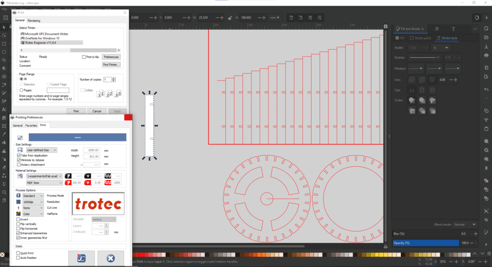
Now, I have chosen the right machine, which is Trotec. When I pressed preferences, a new window showed up; it contained many settings, including the type of material, size of the canvas, and additional advanced settings, so for now, I chose the recommended settings, and of course, I'm planning to learn more in the soon future:
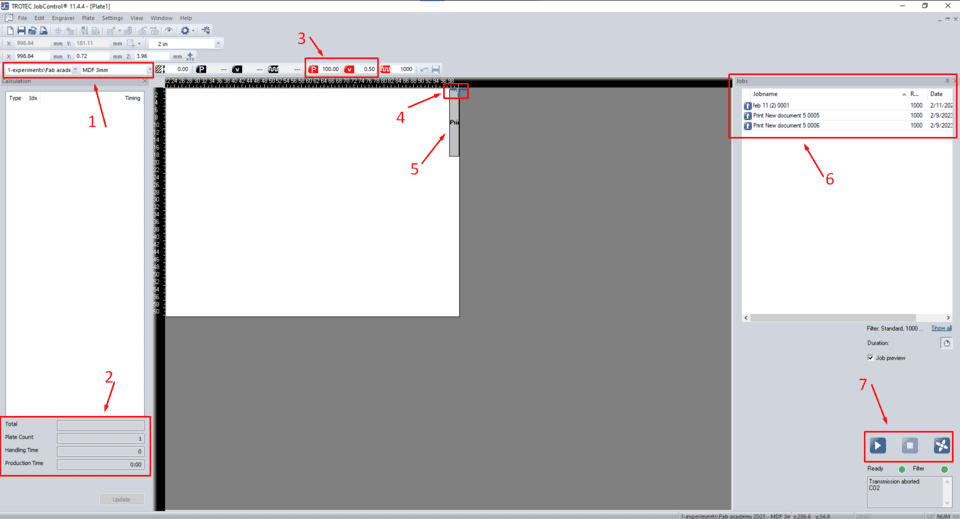
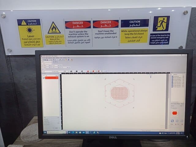
After printing, the job goes to JobControl, which is the official Trotec software to communicate with the machine.
It had many settings:
- 1: Name the group of the material and the material type.
- 2: Cutting time.
- 3: Power and speed values.
- 4: The laser indicator.
- 5: The printed job.
- 6: History of the jobs.
- 7: From the left, Start or pause, stop, vacuum.
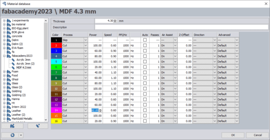
When I double-clicked on the canvas, the material database settings appeared, as shown below we can change the power, speed, PPI(pulse per inch):
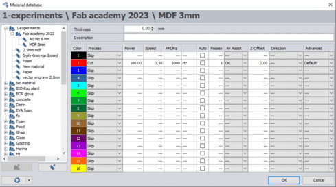
Before operating the machines, I followed all the recommended settings for power, speed, PPI, Hz, and the number of cutting passes, but I also made certain to review and adhere to all the safety guidelines:
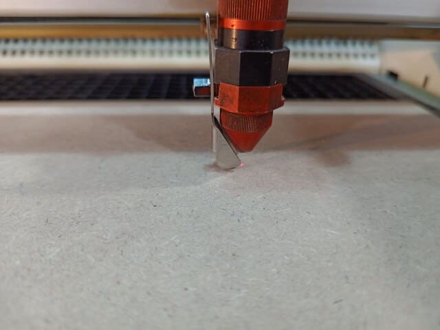
I have put the MDF 4.3mm thick, on the bed and focused on the laser head since it's important to fix the distance between the laser head and the board of the material:
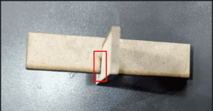
Based on the results on the group assignment, I choose a cut settings as 100 power & 60 speed, after the cut has finished; I tested the joints, it had a small gap, as seen below, so it is not the best press fit, and I forgot about the kerf, and that is why it is so an important parameter to be calculated and this what we did in the group assignment:
So, after we did the group assignment, I had to change the width of the joints, so from the parametric list in fusion, I inserted the kerf value and then edited the thickness of the material by subtracting the kerf from it. Also, I made some tolerance to ensure it would fit correctly, and the result was impressive!
The result:
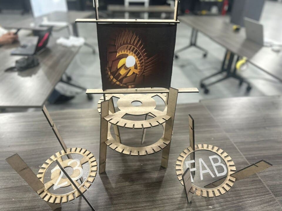
The assembly:
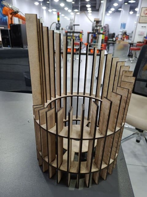
A Hero Shot!:
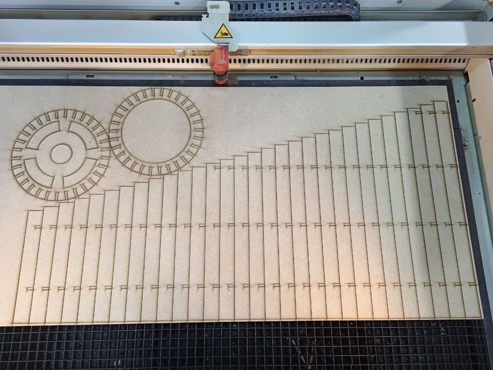
Even though I was so happy with the result, and after I discussed the result with My instructor Emma, it was insufficient to embody the meaning of the modular design, so I thought to give my lamp another purpose, so I went to my design on fusion, and luckily it was parametric, so I readjust the size of the gears, and I make two gears but this time with small size and Following the same procedure I cut them on the laser as shown below:
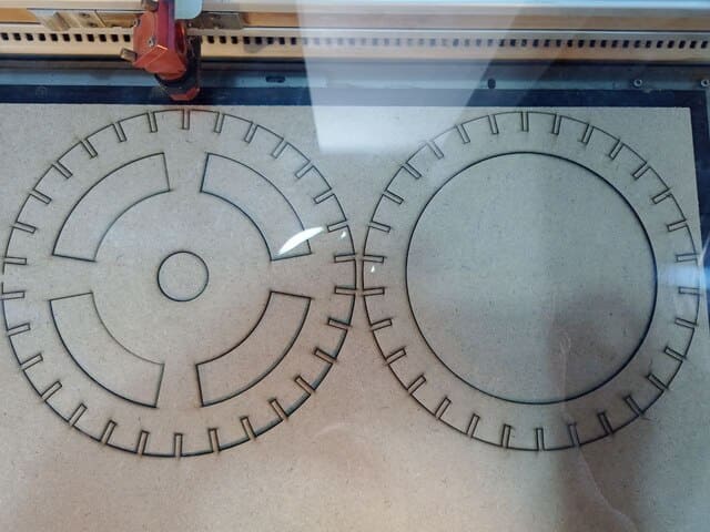
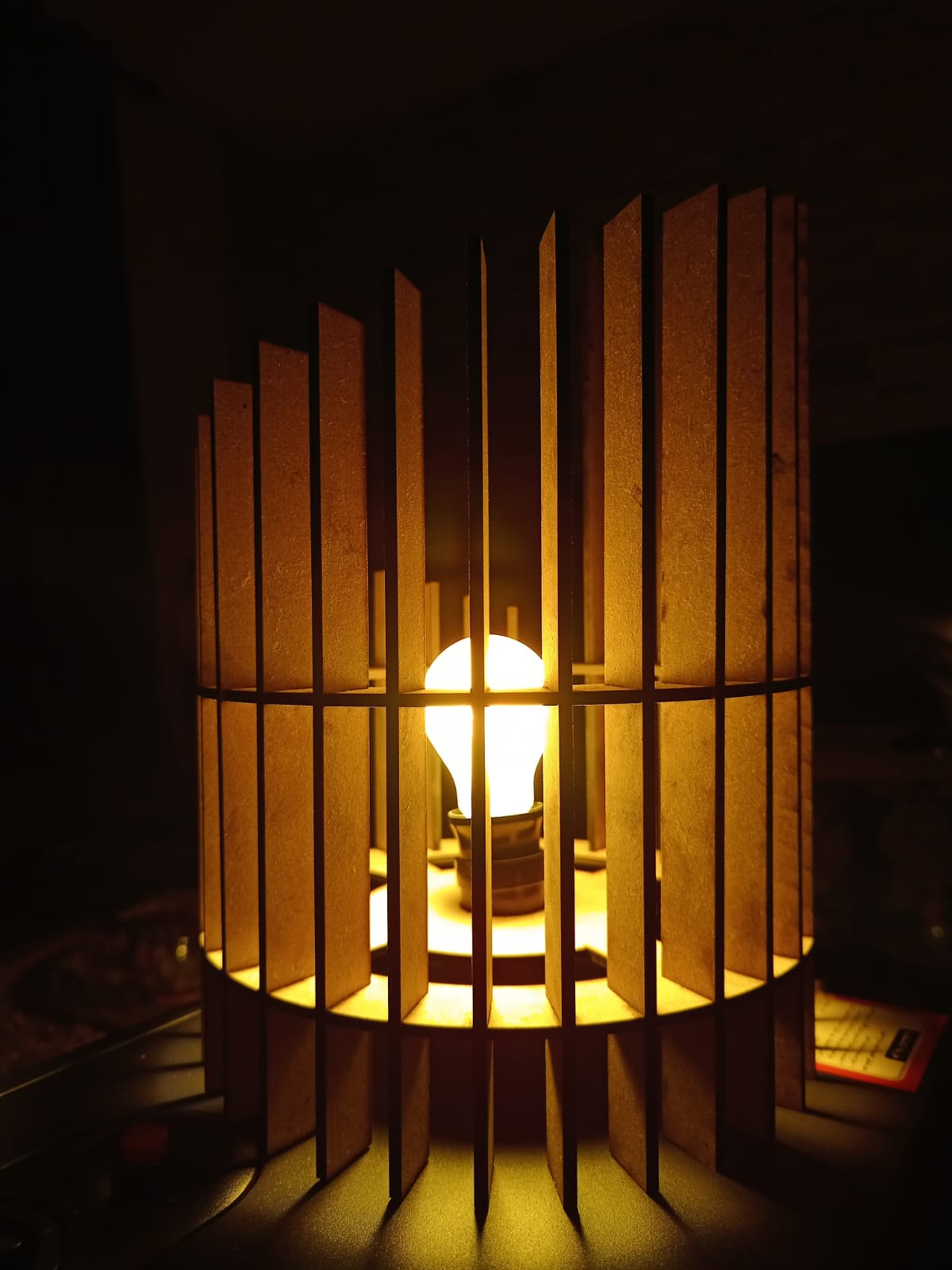
I have to admit, before the lamp was not enough to represent the modular design, but with this fantastic result I could now say It is a modular! :
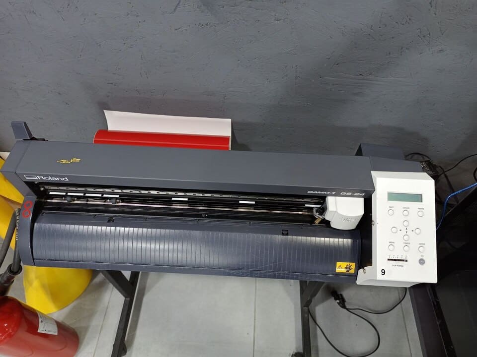
Vinyl Cutter
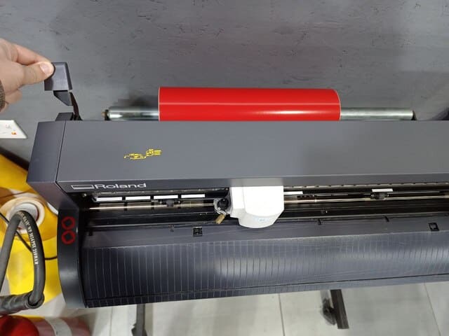
There are different types of vinyl cutters. In TechWorks we have Roland CAMM-1 GS-24:
We can control the machine using the control panel buttons, we can choose what we want to cut either a piece, edge or a roll and that what we usually used:
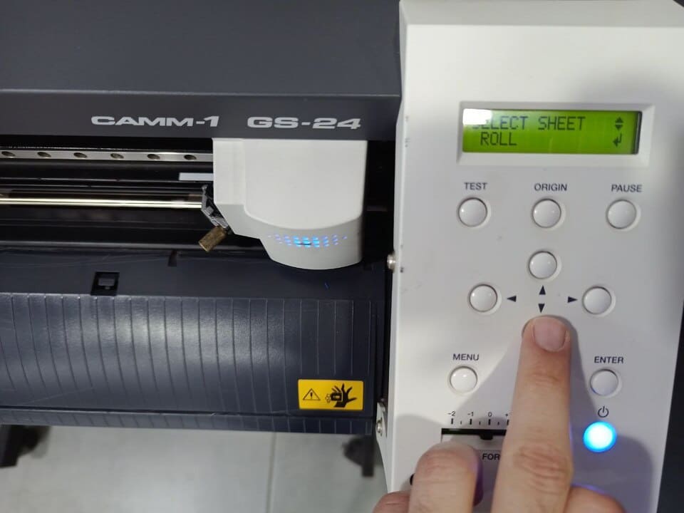
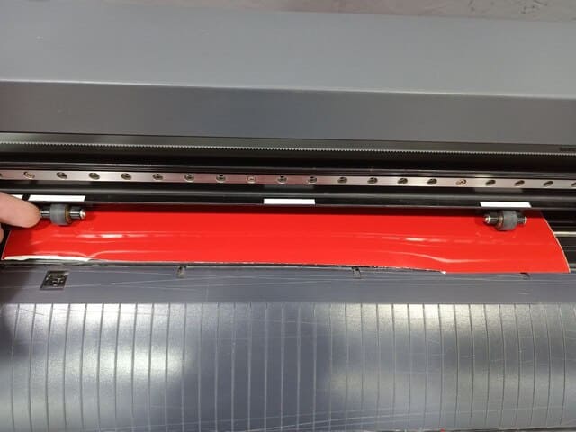
To attach the sticker roll, first I had to make sure that tha handle lever was opened, then I inserted the roll and closed the lever:
It is important to make sure that the rollers is on place under the white bars:
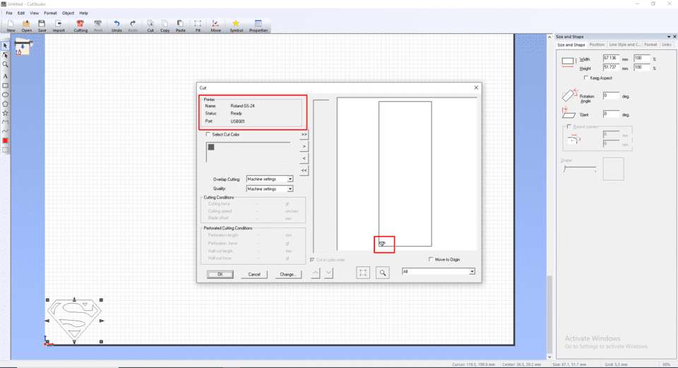
After the installation of the sticker, it's the time to prepare the design to cut, so I used a silhouette photo and opened the photo in Cut Studio:
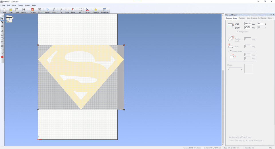
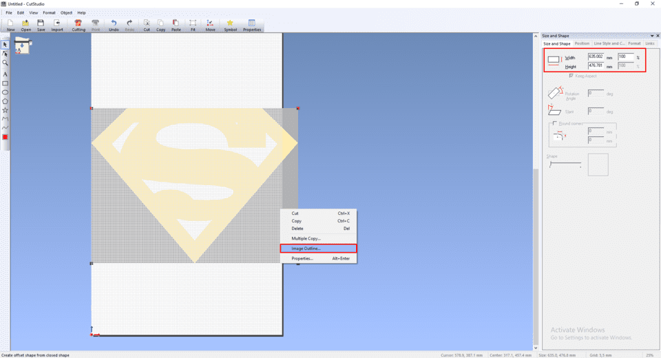
I had to convert the image into vectors, so I had to extract the outlines, also I edited the size of the image as shown below:
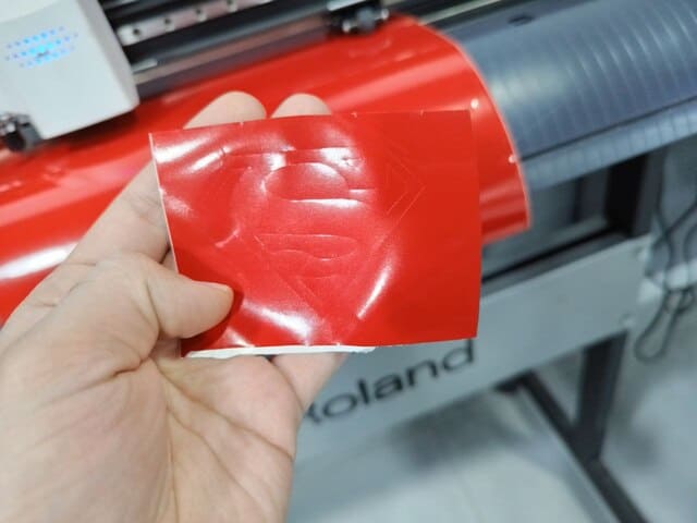
I centered the image at on the canvas, and pressed ctrl+P, to start cutting:
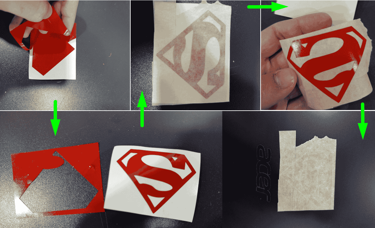
After the cut had completed, I had to cut the piece using a scissor, then I removed the unwanted pieces of sticker, then I used the Masking tape to move the sticker to my laptop, and the idea of using the masking tape it is not too sticky, so it helped me to easily move the shape from the sticker paper to the laptop.
The image below shows how the procedure was:
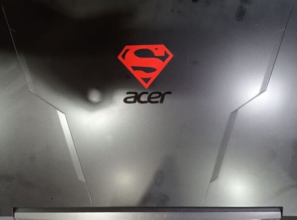
A Hero Shot!