
Output Devices
Group assignment
- Measure the power consumption of an output device.
-
Document your work on the group work page and reflect on your individual page what you learned.
In this assignment we were planning to measure the power consumption for the following components:
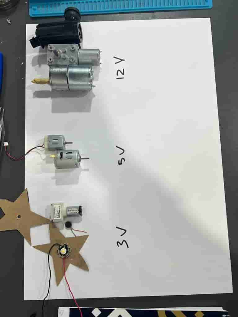
We connected each component with an external power supply, with the rated voltage for each one, and we set a 2A as an upper limit for the current.
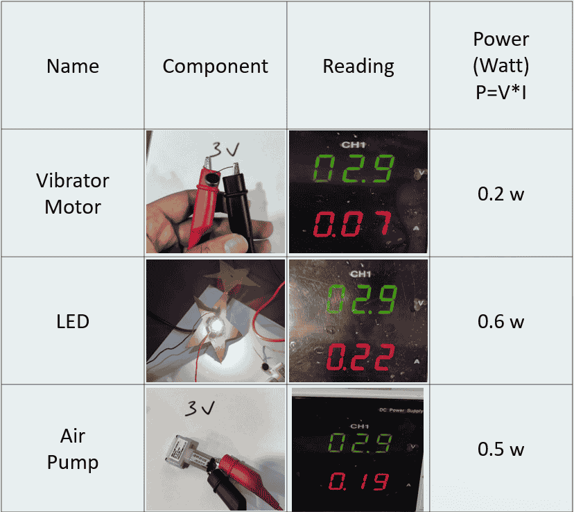
For the first 3 components, the result was as shown below:
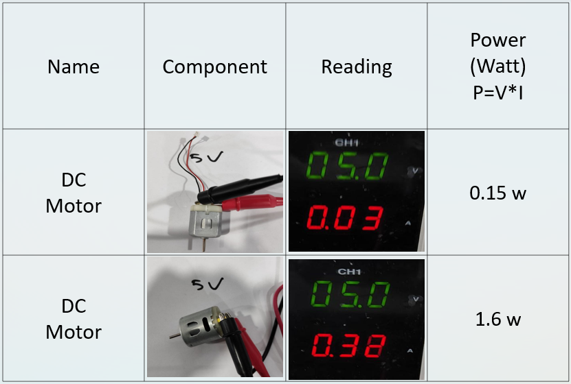
The second test was for the 2 motors below:
The rest of components are shown below:
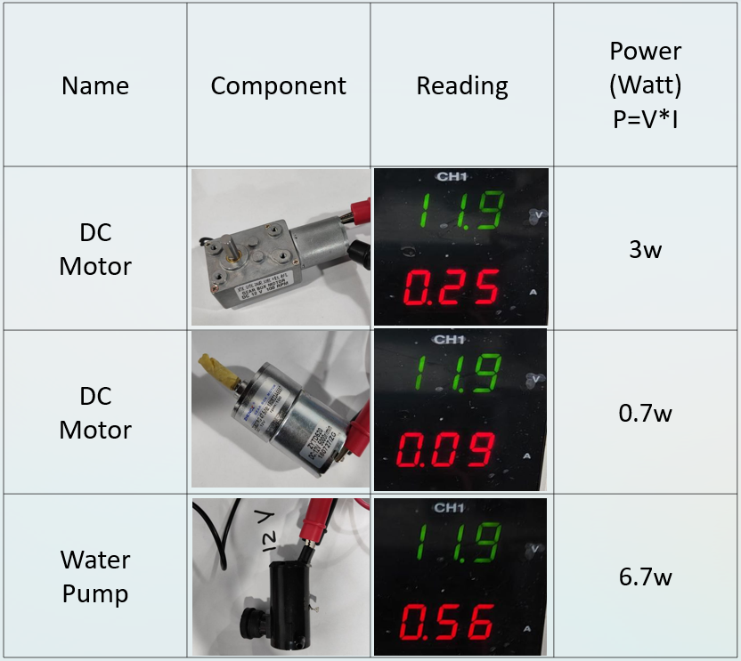
We conclude that every components takes different amount of current, based on the load of the component, higher load means higher current means more power consumption.
Individual assignment
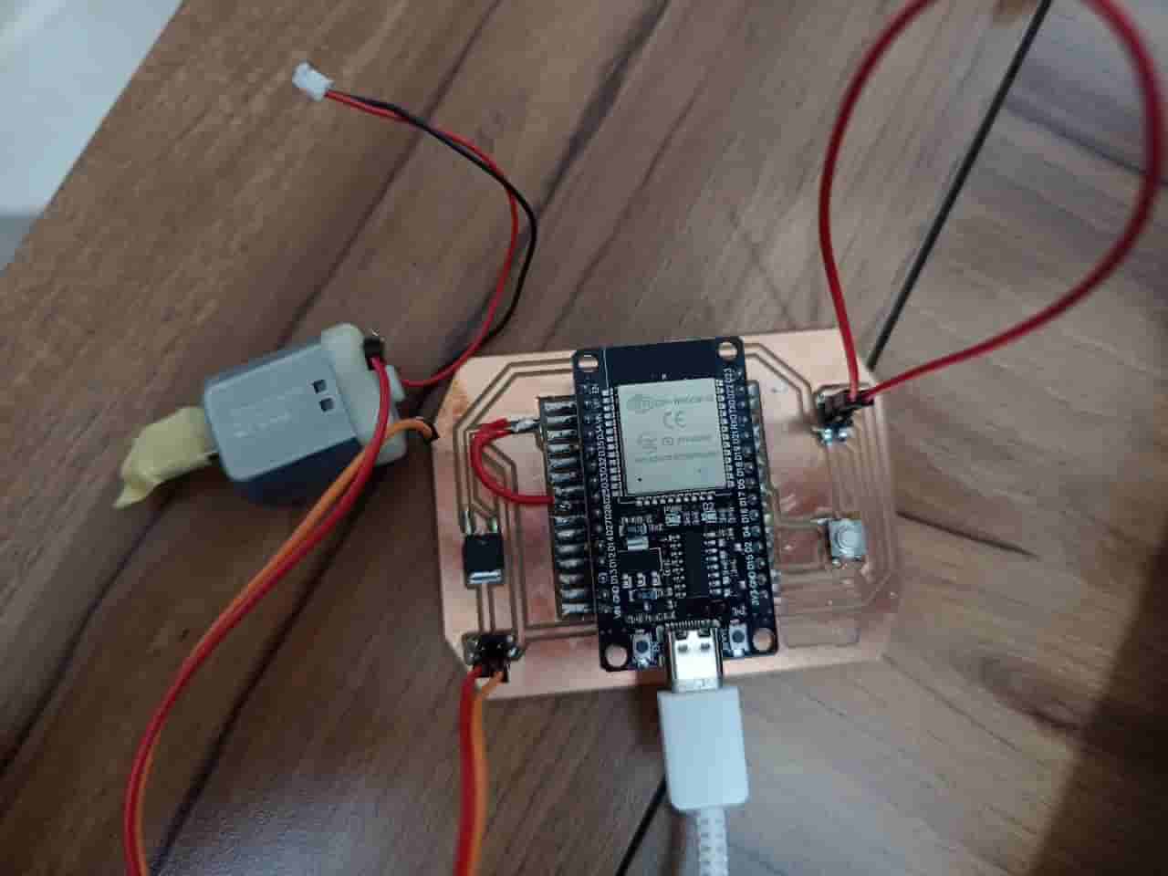
Since this week is to deal with an output devices and I have already designed a board to control a DC motor since it represents an output device in Week08, I will use the same board but this time to control a servo motor.
The board with the previous connection:
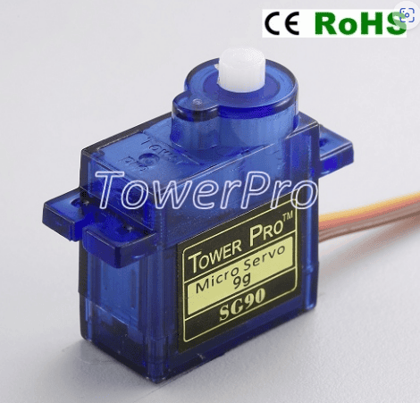
I will use a SG90 servo motor, and since it is the first time I deal with a servo motor, I went through the datasheet of motor and I found that is has 3 lines, 2 lines for powering and the third one is for data to control the position of rotation(PWM).
The pulse width modulation(pwm) is a technique used to control the amount of the power delivered to a certain device, by varying the width of a series of pulses of a fixed frequency the more pulses the more power delivered. In another way the pwm simulate an analog voltage using a digital signal, by rapidly turning a digital signal on and off, here is a helpful video explains what happens.
Servo motors in general are rotates from 0 degree up to 180 degree, However, if we need to rotate a standard servo motor beyond its normal 180 degree range, we can modify the servo by removing the mechanical stop that limits its rotation. This is known as "modifying the servo for continuous rotation", but I should note that it may not provide accurate positioning control and could potentially damage the servo.
To start dealing with the servo on IDE, first I had to install the servo library, the library will let me to interface with the built-in hardware PWM signals on the ESP32 without having to worry about the details of generating the PWM signal.
I installed the library from this Website:
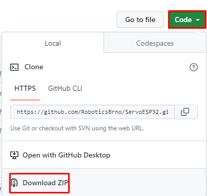
After downloading the library, I unzipped the file and renamed the file to ESP32_Arduino_Servo_Library, then I moved the file to the Arduino IDE installation libraries folder(usually in Documents) then I reopened the IDE.
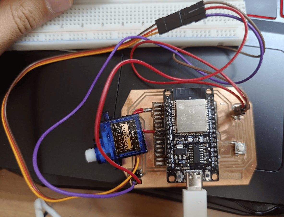
I have connected the servo to a GND pin, and supplied it with 3.3V and the pwm pin was pin number 25.
I wrote the following code, I included the servo library using this command #include
In void loop the digitalRead() function returns LOW if the push button is pressed and HIGH if it's not, if the push button is pressed (pb_status is LOW), The first for loop, for (pos = 0; pos <= 180; pos += 1), gradually increases the pos variable from 0 to 180 in steps of 1 degree,and myservo.write(pos); sets the servo motor's position to the current value of pos. In addition a small delay of 15 milliseconds (delay(15);) is added to allow the servo to reach the desired position smoothly. Finally After reaching 180 degrees, another for loop is used to sweep the servo from 180 to 0 degrees in steps of 1 degree.
                    #include

                      int pb=5; // to define the pushbutton
                      int pb_status=0; // variable to store the pb state
                      int pos = 0;    // variable to store the servo position

                      Servo myservo;  // create servo object to control a servo
                      // twelve servo objects can be created on most boards

                      void setup() {

                        pinMode(pb, INPUT_PULLUP); // set the pb pin as an input pin
                        Serial.begin(115200);
                        myservo.attach(25);  // attaches the servo on pin 25 to the servo object
                      }

                      void loop() {

                      pb_status= digitalRead(pb);
                      if (pb_status == LOW)
                      {
                        for (pos = 0; pos <= 180; pos += 1) { // goes from 0 degrees to 180 degrees
                          // in steps of 1 degree
                          myservo.write(pos);
                          Serial.println(pos);             // tell servo to go to position in variable 'pos'
                          delay(15);                       // waits 15ms for the servo to reach the position
                        }
                        for (pos = 180; pos >= 0; pos -= 1) { // goes from 180 degrees to 0 degrees
                          myservo.write(pos);
                          Serial.println(pos);               // tell servo to go to position in variable 'pos'
                          delay(15);                       // waits 15ms for the servo to reach the position
                        }
                      }
                      }
The result is shown below: