Embedded Programming
Embedded programming is the process of programming a software for small, specialized computer systems that are embedded in other devices, such as appliances, vehicles, medical equipment, or industrial machines.These systems are designed to perform specific tasks and are often low-powered, with limited memory and processing capabilities.Embedded programming typically involves writing code in low-level programming languages,such as C or assembly, to interact directly with the hardware components of the embedded system. The programming requires a deep understanding of the system's architecture, as well as the ability to optimize code for efficient use of system resources.
There are many types of microcontrollers that could be programmed one of them is the RP2040. This high performance MCU has a two independent processors running at 133MHz that can be programmed to perform different tasks, that is means more efficient multitasking and real-time processing of data. also it have 30 multifunction GPIO's with 4 channel ADC(analog to digital converters) with internal temperature sensor, 500ksps, 12-bit conversion, the internal temperature sensor allows for accurate temperature measurements to be taken alongside the analog signal measurements. This is particularly useful in applications where temperature neeeds to be monitored alongside other analog signals, such as in industrial or environmental monitoring with a lot of features that could be found in the RP2040 datasheet.
The Xiao-RP2040 is a development kit board that uses the RP2040 as a MCU, this DEV Kit comes with a type-C interface with 14 pin, eleven of them are pins could be used as input,output and the other 3 are GND and 3.3V,5V as a power pins with 20mm width, 17.5mm height and 3.5mm thickness.

To start using the development board, I add had to the chip to IDE , which is a software that is used to write, compile, and upload code to the microcontrollers. I opened the Arduino IDE and navigated to File > Preferences, and fill “Additional Boards Manager URLs” with this url : "https://github.com/earlephilhower/arduino-pico/releases/download/global/package_rp2040_index.json"

Now I had to navigate to Tools > Board > Boards Manager, search for rp2040 and install it:

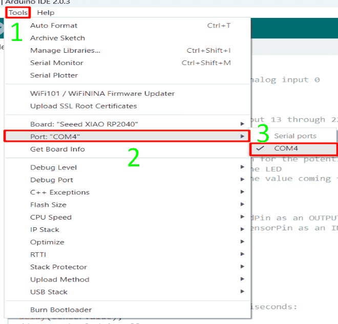
Next step was to select the board and port, but do this I had to connect the board with type-c cable to the laptop so I could interface with the board then I navigated to Tools > Board > Seeed RP2040 Boards and select “Seeed XIAO RP2040“:
Selecting the board

Selecting the port:

I have started with a simple led circuit, which could be like, blinking and fading, and starting with existing code, I had to understand how it worked, and then trying to modify make new objectives.
There are a lot of recommended sketches by our instructor, Emma that could be done on a such circuit:

Before starting, I had to understand the programming language syntax, Arduino C. I followed a list of tutorials and they were useful.
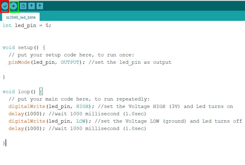
Starting with a blinking led circuit.The sketch of the blinking led as shown below,
The sketch mainly consist of three parts:
- Global: where I can define a global variables that could be used anywhere on the sketch.
- Void setup: Where I define the pins and commands that will runs only once.
- Void loop: Where I set the functions that run repeatedly.

In global, the syntax int is used to sign a value to a certain variable. Then the code enters void setup; pin mode is used to define the objective of the pin, whether input or output.
After that void loop starts with digital write which tells the micro controller to give the pin high voltage, then the delay command, which tells to wait for a certain amount of time before continuing to execute the code:
From many recommended and available sketches by our instructor, the first sketch I have choose to test was blinking led circuit, this sketch set the voltage of the led high and low with a specific amount of time for each value, the time depends on the delay value, the 1000 value means 1000 milliseconds, and this is equal to one second, the sketch sets pin 5 as an output then sets the time of on and off, to verify the code I clicked on the red box, and then I connected the board, I have chose the right board and port then I clicked on the green box to upload it:

After uploading, the video below shows how the Sketch works:
I tried to reduce the delay time by changing the value from 1000ms to 100ms, it was blinking faster:
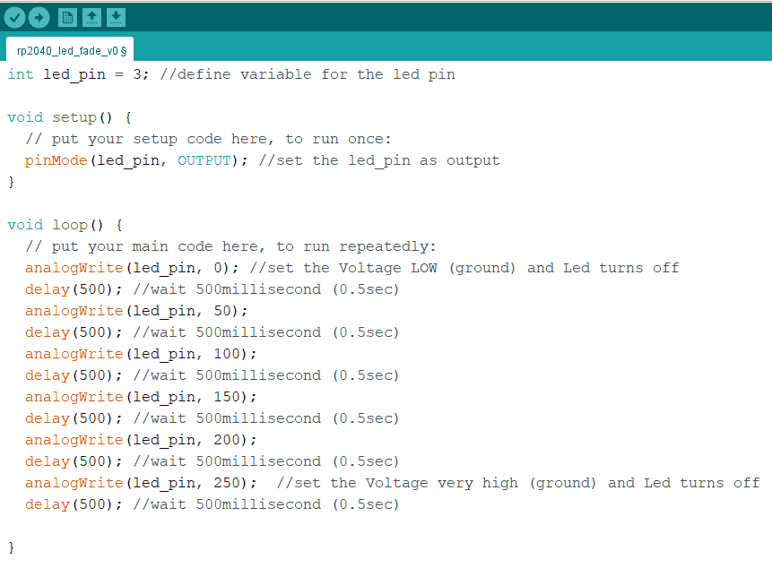
The second sketch that I have downloaded to test was to make the led fading with different amounts of brightness, the brightness of the led are represented by a values ranges from zero to 250, zero means led are off and 250 means maximum led brightness, so the sketch mainly manipulate with those values on different time intervals, each 0.5 second has a certain value of brightness as shown below:

The video below shows how the sketch works:
I tried to add another led,but I set the value of the brightness descending from 250 to zero, and the result was cool:

The video below how the sketch of the two leds are fading opposite to each other:
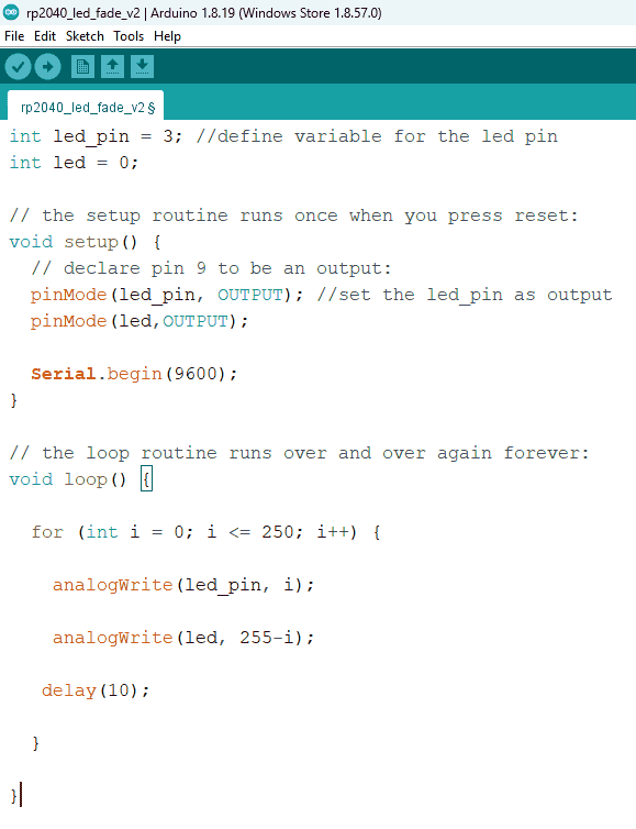
The third sketch that I had downloaded is also to make the led fading, but it contains for loop which basically works as a counter so maximum brightness when the i value is 255 and off when i is zero, and we can see the counter from the top right icon:

The video below shows how fading looks like as smooth not like the previous code that looks like steps:
I tried to edit the sketch by adding a red led, first I had to define a new led pin then I added a new condition inside the for loop, so basically when i counter equals to zero, the yellow led value will be zero and it will be turned of while the red led value will be 254 and this is the maximum brightness, the loop continue util the i counter value reaches to 250 so the yellow led value become 250 and the red value become 5 and it almost off.

The video below shows how the two led fadings opposite to each other:
The fourth sketch that I had downloaded was fading back and forth, the value of the brightness ranges from zero to 255 but it will start from 5, then it will increase until it reaches the 255 so the if statement condition become true if the value is 255, then it will and reverse the fade amount value to -5 so the brightness starts the degrade until it reaches 0 then the if statement becomes true then reverse the fade amount to 5 so the brightness increases. from tool list, serial plotter, it shows how the value of the brightness ranges from 0 to 255:

The sketch of the circuit:

The video below demonstrate how the fading ranges between the values 0-255:
For the wifi connection I downloaded the sketch, and used Seed-ESP32-C3. The module is designed for low-power and cost-effective applications such as smart home devices, wearables, and IoT sensors.
I have followed the previous procedure to add the chip to the IDE, so I opened the Arduino IDE and navigated to File > Preferences, and fill “Additional Boards Manager URLs” with this url : "https://raw.githubusercontent.com/espressif/arduino-esp32/gh-pages/package_esp32_dev_index.json" and now I had to navigate to Tools > Board > Boards Manager, search for Seed-ESP32-C3 and install it:

Now I had to run the Wifi sketch on the ESP32, the sketch will show the available networks in my area, so when the sketch runs it will returns the number of the available networks, if the value was zero that means no network available then if it is above zero it will execute the if statement so it wil print and order the available networks by SSID which is the network name and the RSSI which is the received signal strength indicator. The sketch also marks the closed networks with star, then after the scanning completed it said the scan is done. :

After uploading, the result shows all available networks, and I noticed that our closed network are remarked with star which means the code runs correctly:

I tried to make a communication to turn a two led's, on or off by using this helpful website, after I downl it I opened the Sketch, and modified the network name and password then I set the GPIO pins of 26 to pin number 2 and GPIO 27 to pin 3 :

The ESP32 with the Wi-Fi module can be worked as either a Wi-Fi station that could be connected tho the internet router like smartphones or laptops and transfer data, or it could be an access point that directly interacts and communicate between devices without needs the internet router.
After running the program, the ESP32 now works at the same time as a Wi-Fi station so it could be used to interact with the internet router, and an access point, that it could interact and connect with other networks directly with a local IP address, since each router has an IP address.
The sketch gives me an IP address, this IP address works as local network. When I open this IP address using my phone on the browser, this means than I can now interact with the ESP32 directly.
From the serial monitor, where I found the IP address:

So I have copied it and paste on the internet search engine, then it opened the control page as shown below, when I pressed turn on the MCU sets the value of the led High and with turn of the value of the led is High. Note that the phone should be connected to the same network of the development kit network.
Group assignment:
The group assignment was to test the performance of different modules and to compare the number of iteration at the same period of time.
I have started with Seed-ESP32-C3 and the result was:

Then the second iteration was using ESP-WROOM-32, and the result was as shown:

We used also arduino NANO, and the result was as shown:

For arduino UNO:

Finally the RP2040:

Conclusion
The table below compares the five microcontrollers we tested, and we conclude that all modules are different development boards used for building electronics projects. Each board has features and capabilities, making them suitable for different projects. But on the other hand, the RP2040 was the fastest in the same amount of running time.

In my opinion, choosing which microcontroller depends on the project's requirements. The ESP-WROOM-32 or Seed-ESP32-C3 may be the best choice if the project needs Wi-Fi and Bluetooth connectivity. Suppose the project needs a smaller board, as a hobbyist project and prototyping; The Arduino NANO may be a better option. The Arduino UNO may be the best choice if the project needs a widely used board with a large community and support. And if the project needs a board with high-speed data transfer and low power consumption, the RP2040 may be the way to go.
