
Input Devices
Group assignment
We want to test two types of input devices, one gives digital signal(pushbutton), and the other gives analog signal(light sensor), we used the digital multimeter to read the voltage across the resistor for the following circuits:
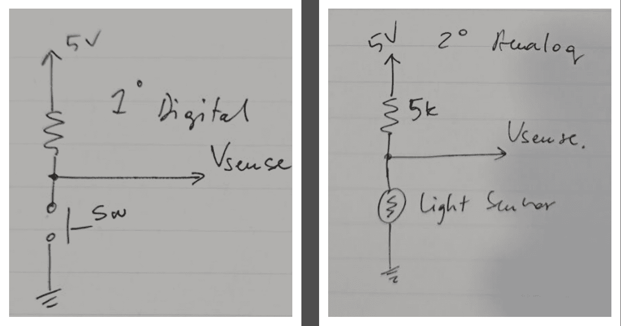
For the pushbutton circuit we supplied the circuit with 5 volt and we used a 5k ohm resistor, when we pushed the button the current flows across the resistor and the voltage reading on the multimeter was exactly the same as the supplied, and it was either 5V or Zero:
The video below shows how it works:
For the LDR(Light Dependent Resistor) is sensitive to the light, when the amount of the light that falls on the LDR increases , the resistor will decrease, the voltage across the LDR will decrease and we noticed that the value of the voltage was ranging and does not have a fixed value like pushbutton.
The video below shows how it works:
We conclude that digital signals have two-state (0,1) when it has the state of 0 that's the means 0V or low voltage, but if the state was 1 that's the means high voltage and that depends on the logic voltage on that system, while the analog values was ranging and the value of the voltage was changing over time when the amount of light directed to the LDR was changing.
Individual assignment
Input devices are any device or components that used to enter or capture data, like keyboard, scanners, sensors etc.
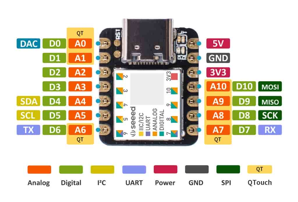
For this week I am planning to use a touch sensor to control a motor. to make this happens, I will use Seeeduino XIAO development board, it comes with SAMD21G18 CPU running at up to 48Hz. It has 256KB Flash and 32KB SRAM on board and supports the USB Type-C interface which can supply power and Uploads codes.
This kit comes with seven pins working as a touch pins:
The idea behind the touch pins that the touch pins works as a capacitive sensors, capacitive sensor works by measuring changes in capacitance, which is the ability of a material to store an electrical charge. Capacitance is measured in units of Farads (F).
A capacitive sensor consists of two conductive plates separated by a dielectric material. When an object is brought near the sensor, it causes a change in the electric field between the two plates, which changes the capacitance of the sensor. The amount of capacitance change is proportional to the distance between the object and the sensor and here a useful video explains how does the touch sensor works.
To start working with this kit, and following the same procedure on week 4, I have added the board to arduino IDE using this link: "https://files.seeedstudio.com/arduino/package_seeeduino_boards_index.json"
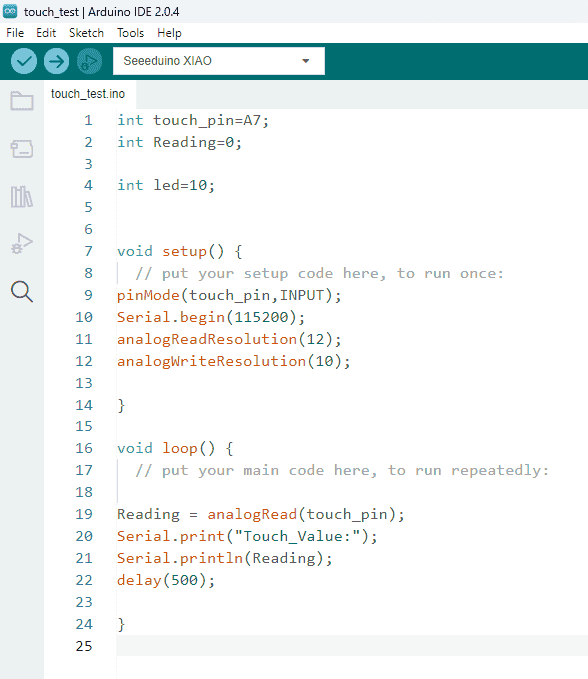
After installing the board, I wrote the following code to test the touch sensor:
The video below shows how it works:
To explain what happened, the pin A7 works as an analog pin, which means values between 0 and 1023 will set the voltage to somewhere between 0 and 3.3V.
Each touch pin has a build in resistor and capacitor inside, when the voltage value of the pin equals to 3.3V it will let the current flow until the capacitor filled with charges, and when I touch the pin the capacitor starts to discharge this energy, the discharge time depends on the size of the capacitor, more capacity(more charges stored) in the capacitor, the more time it would take in discharging.
So in my case, when the code runs, it sets the voltage of the pin as 3.3V which is equal to 1023, and when I touch the pin, the pin will be disconnected from the voltage source and starts to discharge until the value of the voltage reaches zero(no current flows).
Even I was working with the analog pin and reads the values ranging from zero to 1023, actually for the touch pin things are working in different way, to make it clear, I used the analog read as an input pin but actually to use the touch pin in a proper way the capacitive touch sensing involves detecting changes in the capacitance of a capacitive touch pad or surface, which is influenced by the presence or absence of a conductive object (such as a finger) nearby.
To accurately sense touch using capacitive touch pads, I need to measure the timing of the capacitor's charging and discharging cycles. This information allows me to determine if the touch pad has been touched or not. It's not just a matter of reading a voltage level.
There is a library called "Adafruit_FreeTouch.h" library that I have used below is specifically designed to handle the capacitive touch functionality of the SAMD21 microcontroller. It provides the necessary functions to initialize the touch pins and measure the charging/discharging cycles accurately, giving a reliable touch sensing capabilities.
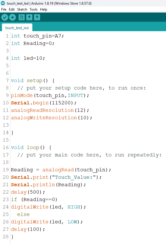
I wanted to start doing something using this touch pin to control some outputs, so I tried to make it to control a LED, when I touch the pin, the LED should lights up.
To do this I wrote the following code:
The video below shows how it works:
After testing, since my final project have a stepper motor, I wanted to make a pcb to control the motor using the touch sensors, following the same procedure on week06 I went to this website, and I have installed the Seeeduino XIAO library with addition to Motor driver library and added them to eagle library.
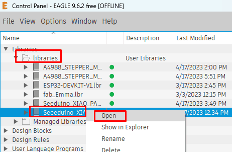
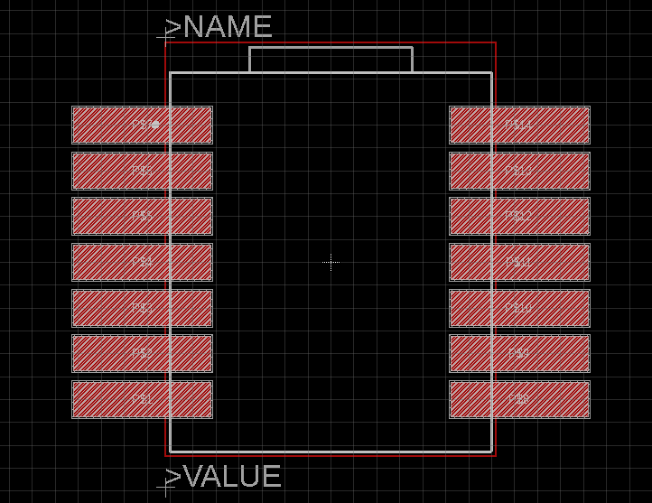
When I downloaded t the schematic for the MCU, it was with holes on each pin, and since I need it with pads so I can solder the pins with the pads, I had to edit the library it self, and to do this I opened eagle and then opened the MCU library:
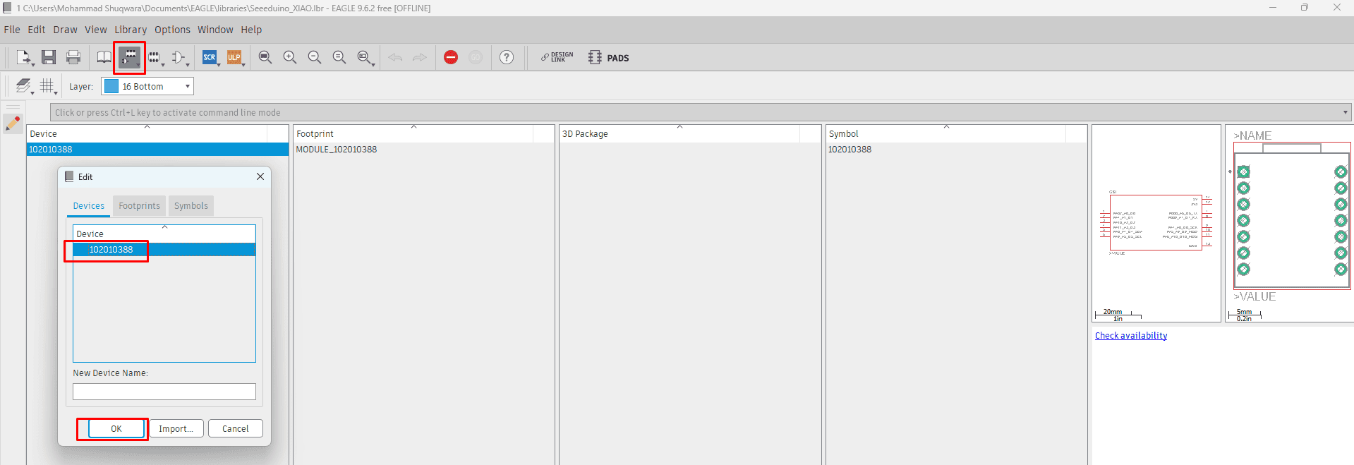
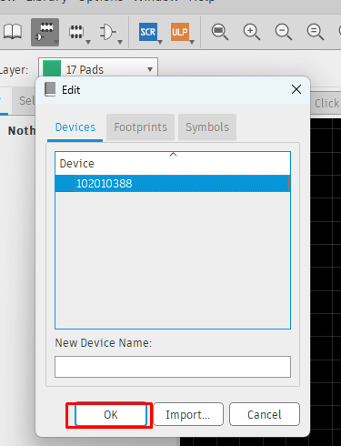
I selected the device button at the top bar,then selected the module > pressed ok :
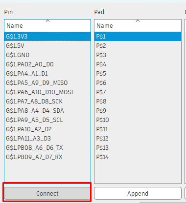
After choosing the module,Next step is to disconnect all pins, I toke a screenshot for the pins name and there number, because I will need them when reconnecting:
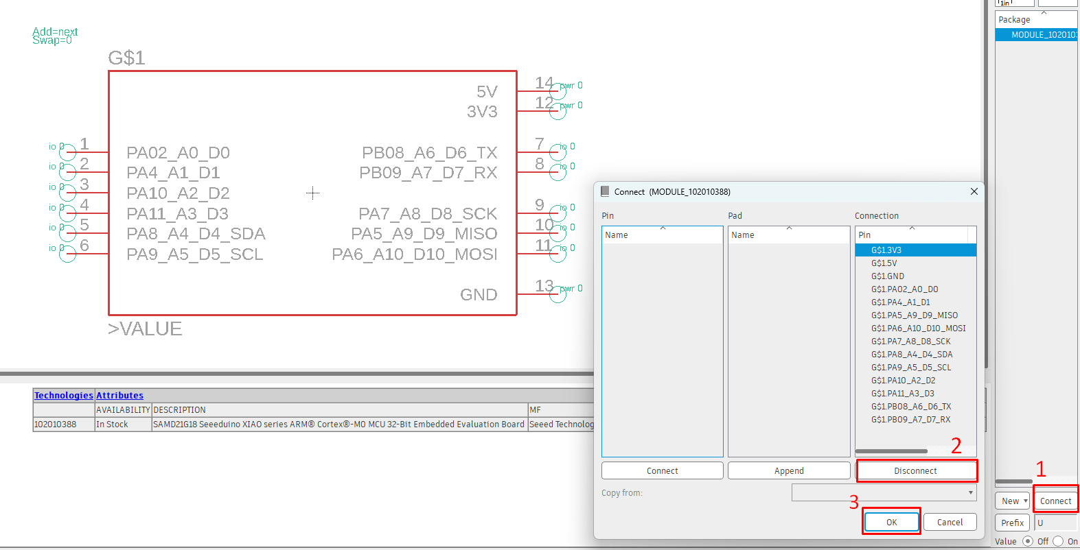
All pins should be disconnected then I pressed ok to continue the process:
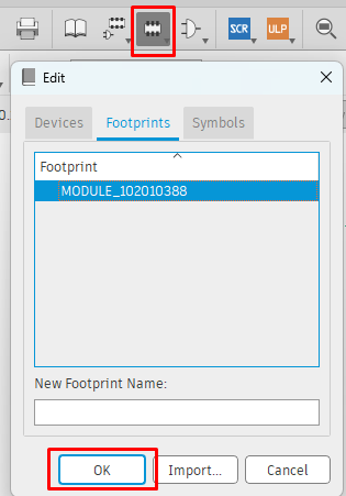
From the tool bar at the top, I navigated to footprint, then I selected the module and pressed ok:
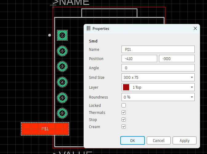
From the layer list at the top bar, I make the first layer only visible them from the left side tool bar I selected the smd tool and I put it on the first pin, to edit the smd pad I clicked on it and set the dimension to be 300*75:
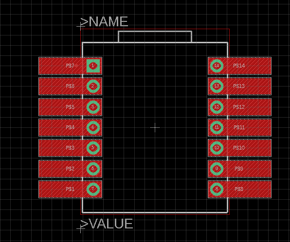
Using copy command, I copied and pasted the pads to the other pins:
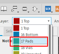
In order to delete all through holes, I selected the pads layer only:
Using delete command, I deleted all holes:
Back to the device, I selected it and pressed ok:
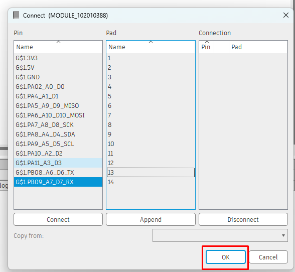
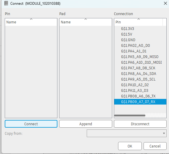
Final step is to reconnect the pins, it is important to connect each pin name with the correct pin number:
After connecting all pins, I pressed ok to finish the process:
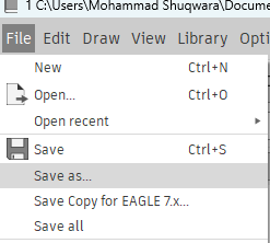
Final step is to save the footprint, from file save as and set the location:
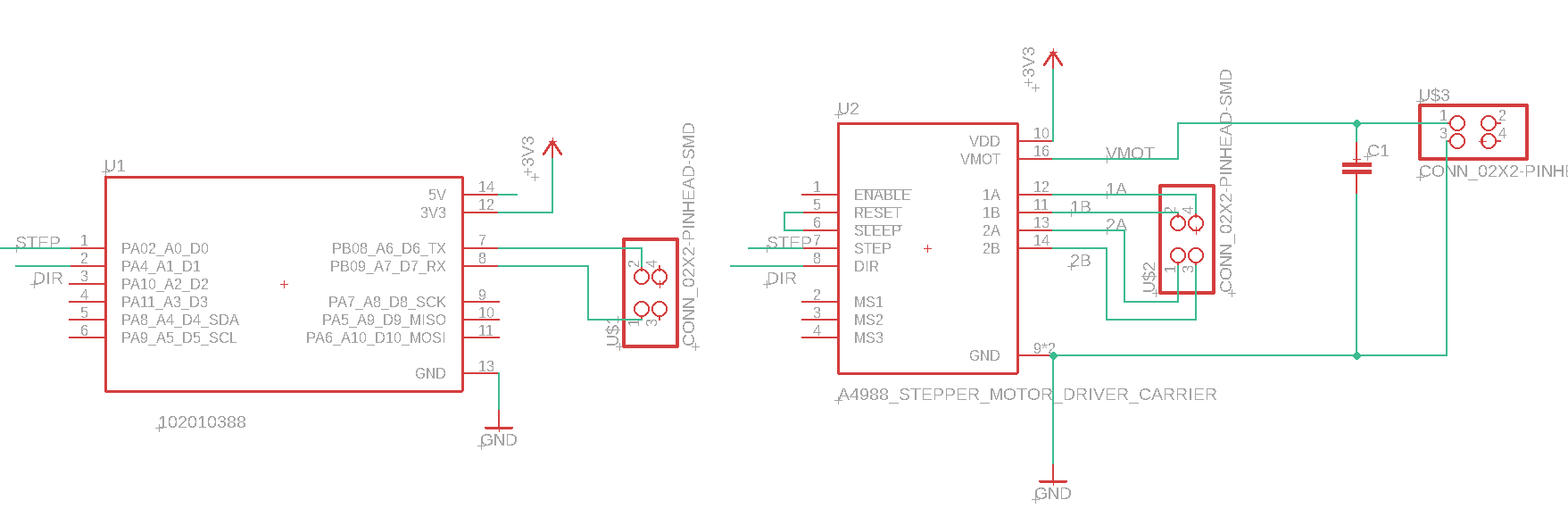
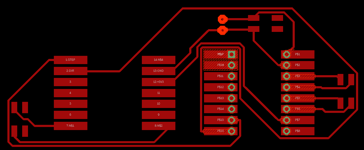
For designing the circuit, this video was helpful to start with stepper motors and to see how the connection of the circuit, the images below shows the schematic and the board of the circuit:
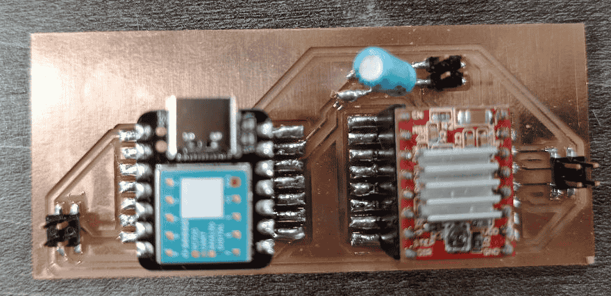
To cut the board, I followed the same procedure on week08, and then I soldered the components as shown below:
For now I want to use the touch sensor without the motor driver, so I wrote the code, by use and modify this code as follows:
              #include "Adafruit_FreeTouch.h"
                Adafruit_FreeTouch qt_1 = Adafruit_FreeTouch(A6, OVERSAMPLE_4, RESISTOR_50K, FREQ_MODE_NONE);
                Adafruit_FreeTouch qt_2 = Adafruit_FreeTouch(A7, OVERSAMPLE_4, RESISTOR_50K, FREQ_MODE_NONE);
                int qt1 = 0;
                int qt2 = 0;
                int qt_Threshold = 850;


                void setup()

                  {
                 Serial.begin(115200);
                  }

                void loop() {


                  if (! qt_1.begin())
                    Serial.println("Failed to begin qt");
                      if (! qt_2.begin())
                        Serial.println("Failed to begin qt");

                        qt1 = qt_1.measure();

                      if (qt1 >= qt_Threshold) {
                        Serial.println("Touched1");
                      delay (500);
                      }
                      else {
                        Serial.println("Untouched1");
                          delay (500);

                      }

                        qt2 = qt_2.measure();

                      if (qt2 >= qt_Threshold) {
                        Serial.println("Touched2");
                          delay (500);

                      }

                      else {
                        Serial.println("Untouched2");
                          delay (500);

                      }

                      }
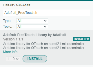
In order to start using the code, I had to install the Adafruit_FreeTouch.h library, so from IDE, I have navigated to tools> manage libraries> searched for the Adafruit_FreeTouch.h and installed it:
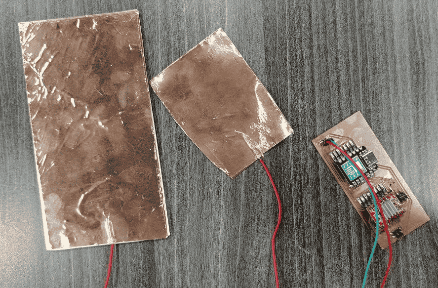
Because I want to use at least 2 pads to control the scanner rotation, I made a 2 pads using copper tape and connected them to the touch pins as follows:
Now, it is the time for testing, I have connected the board and uploaded the code, the result was as shown below, I noticed when I touch both sensors it goes zero, this because the body works as ground and therefore the current will discharge to the body: