Electronics Production
Roland Machine
Starting this week with a new machine Roland monoFab SRM-20, this machine we have here in TechWorks, it is a compact desktop milling machine, it could mill different types of materials like copper, plastic, chemical wood, foams, wax,etc, it comes with 232mm(X)*157mm(Y)*60mm(Z) workpiece table:

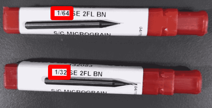
For this machine we will use 2 types of endmills which are 1/64inch(0.39)mm and 1/32(0.8)mm in diameter, the 1/64 will used to make the copper traces and the 1/64 will be used for the cutting the copper board and for make drilling.
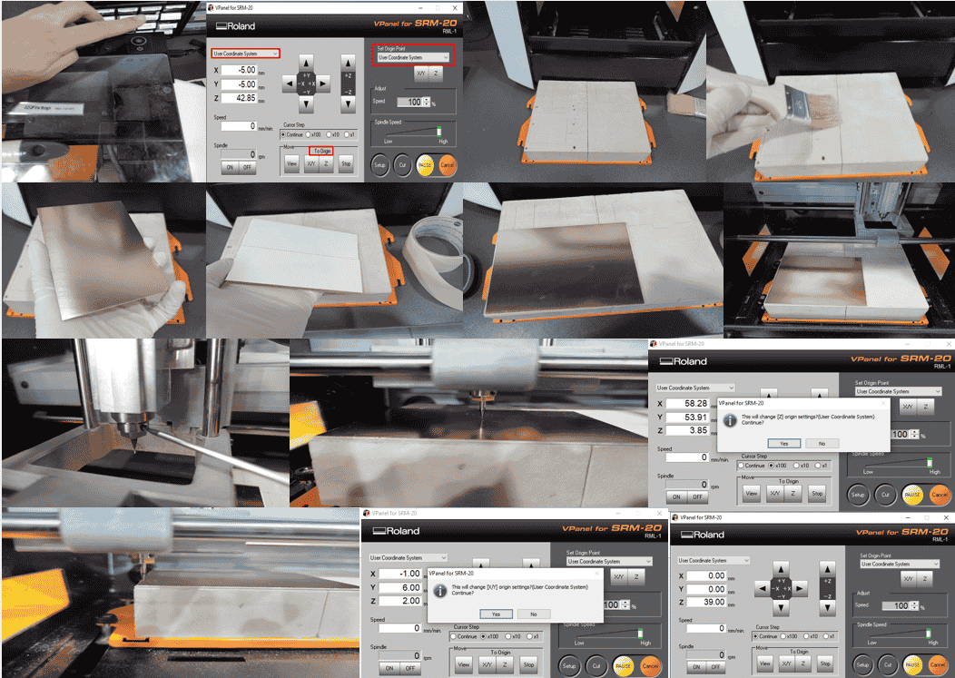
Before starts any job, good preparing of the machine is mandatory, and to do this I did those steps:
1- I turned the machine ON then I opened Vpanel(the machine interface).
2- I moved the y axis toward me, then I removed the platform of the sacrifice bed.
3- I cleaned the sacrifice bed well, any dust will prevent the copper board to adhere correctly.
4- I took a copper board, I made sure to not touch the copper with my bare hands, any fingerprint on copper maybe will cause an oxidization to the copper.
5- I used a double faced tape to adhere the copper board, I made sure to not overlap the tape, since it will led to un leveled copper plate.
6- I tried to cover all copper board with tape, it is okay if there is tiny gap without tape.
7- I put the copper board on the sacrifice bed, then I returned the platform to the machine and well attached the platform with the screws.
8- I inserted the endmill by unscrew the head of the Z axis, then I pushed the tool to the tool holder and tightened the screw a bit.
9- I moved to the user coordinate from Vpanel.
10- I moved the z axis down, when I almost reached the surface, I switched to small steps to not break the tool, when I had a small gap between tool tip and copper board I unscrewed the endmill holder, let the tool touches the copper board then screwed the holder again, now I pressed on zero z, now z axis zeroed.
11- I raised the z axis, then moved to the front left corner, I zeroed x,y by pressing on x,y zero also from Vpanel.
12- I moved the platform to random position then clicked on move x,y origin to check if my origin is correct.
13- Now the machine is ready.
Test and practice
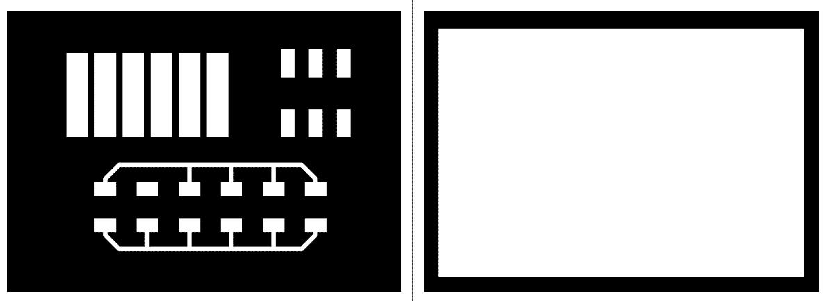
To firstly practice mods, milling, and soldering, thanks to our instructor Emma, she prepared for us the png pictures, traces and outline from the Eagle software and she showed us how export the png files from eagle and that what I will show in the Individual assignment below.
The trace and outline pictures are shown below:
To prepare the png pictures and convert the traces and outline to toolpath, I opened the modsproject website, then > Right click on canvas > Programs > Open Program > Roland > SRM-20 mill > PCB, then the module below shows up:
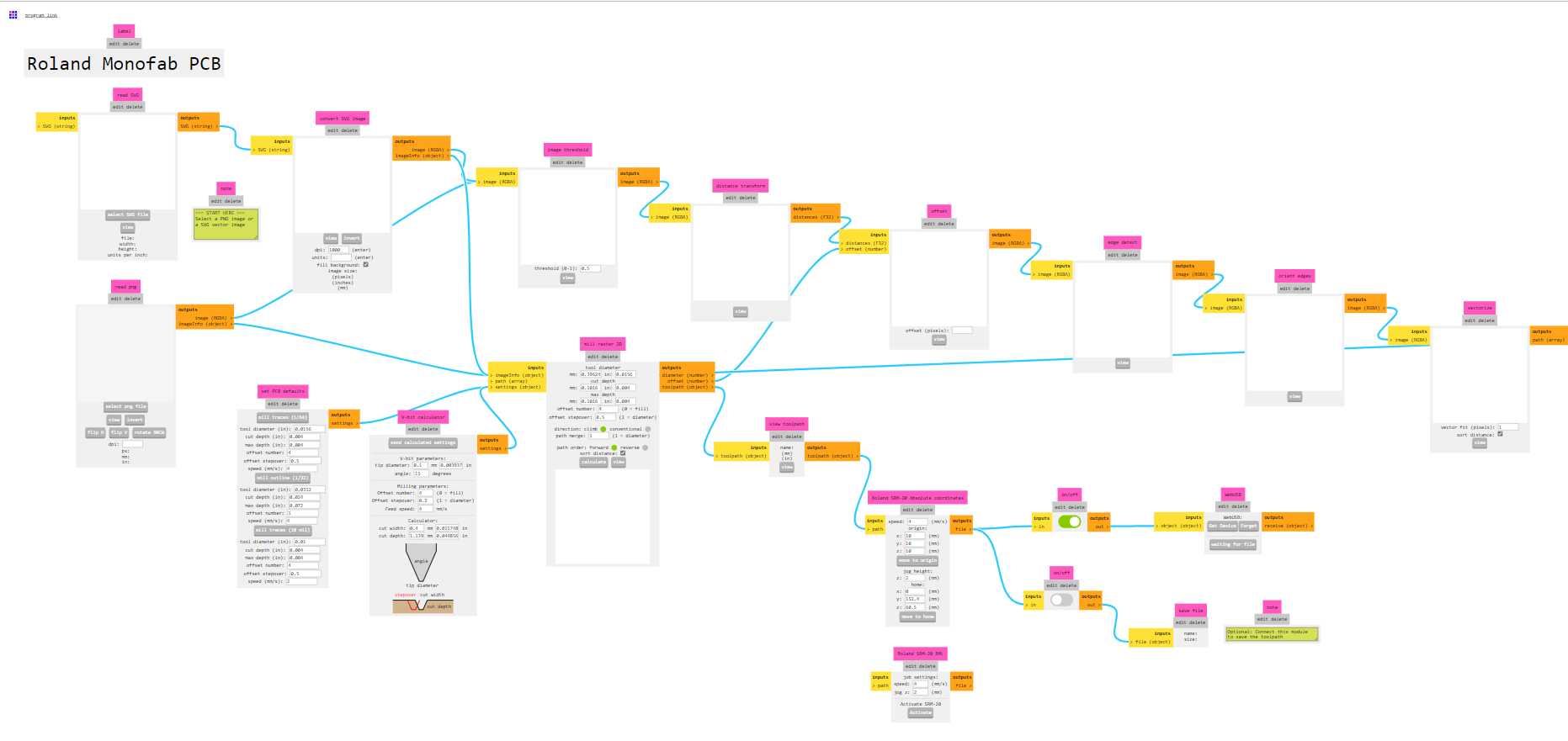
Now to add the pictures, from mods > select png file, changing the dpi will change the schematic size but I will keep it 500:
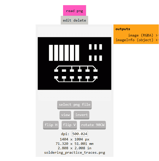
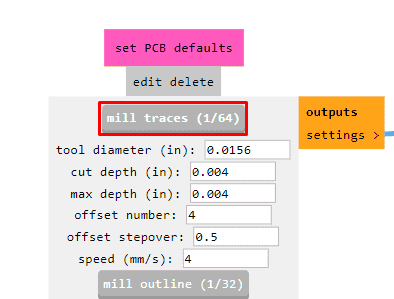
Then I selected mill traces 1/64 with the following settings:
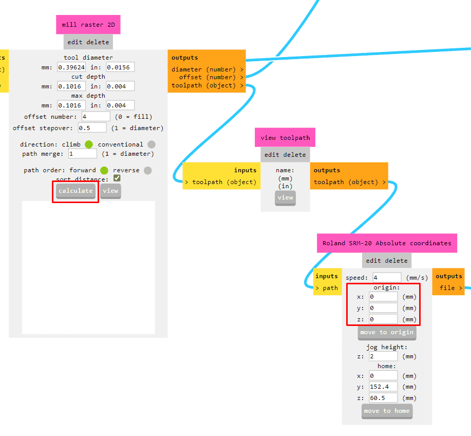
From the following block, I calculate the toolpath, note it is important to set x,y,z origin as zero:
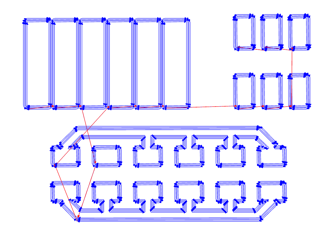
After calculating a new window opens with the result of the toolpath, note that the white area will be the copper pads(pads are the copper pieces where we will solder the components):/p>
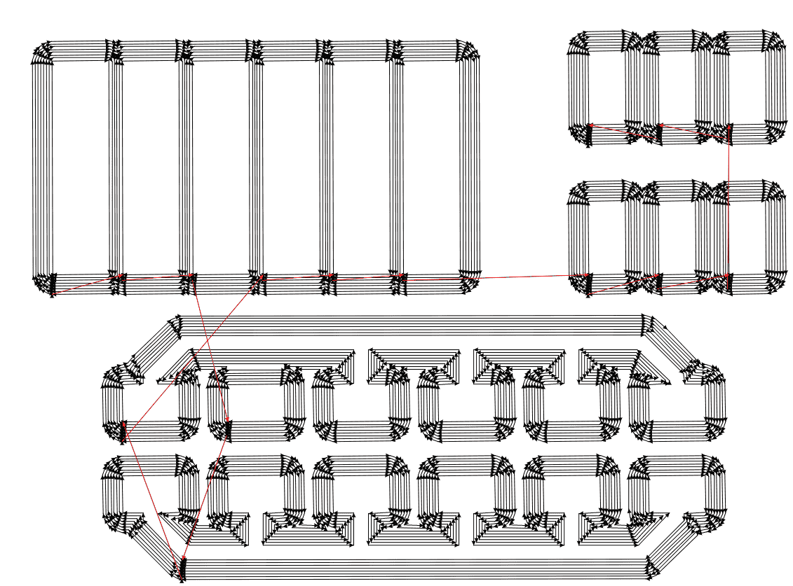
If I doubled the offset number to eight, the result shows an increase in the number of tool paths so less copper around the pads, I think increasing the toolpaths is helpful when dealing with tiny pads:
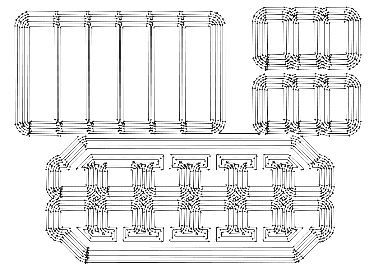
Also I tried to increase the offset step over to 1 so it will equal to the tool diameter, the result shows that the tool will clear more copper, so in general if we have small details it should to stick with small values, as a rule of thumb half or less of the diameter:
The file now ready, I clicked on save file then the file automatically downloaded:
For the cut operation and following the same procedure, I uploaded the cut png, with 500 dpi but I chose mill outline:
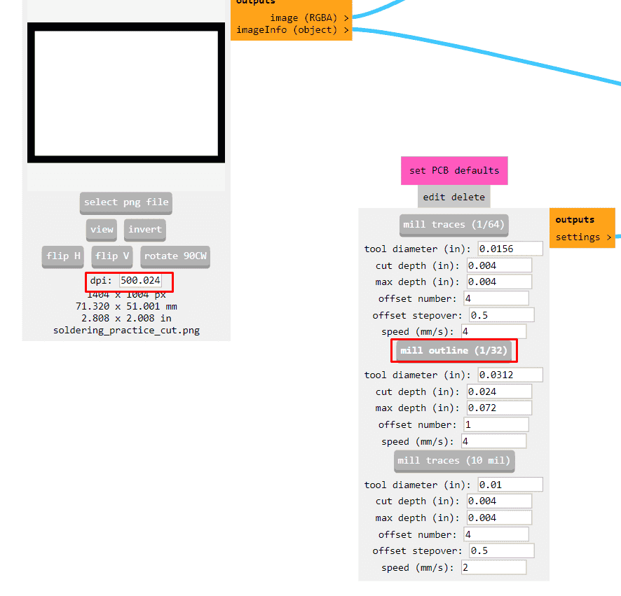
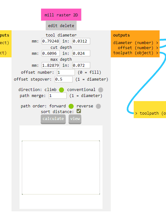
Before calculate, I checked the values of the diameter, cut depth and I noticed it have more depth than traces, offset number and tool step over and the result as shown below, then I clicked calculate, note I set also the x,y,z origins as zero also then I saved the file:
After preparing the machine following the previous steps, and to cut the trace file, from vpanel, I pressed on cut, then I chose the traces file then output, and the cutting will start:
After the machine finished the traces, following the same procedure, I went to cut then chose the cut file then output to start
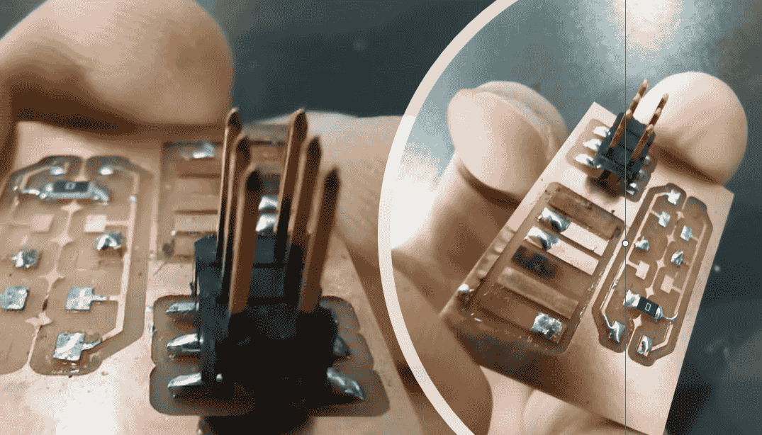
Unfortunately, I did not took a picture before start soldering and practice on the board, I used zero ohm resistor and connector to practice and here is the result for my firs soldering:
Tips for soldering:
1- Wash the board with water and soap before soldering, this will help components to stick correctly without any obstacles.
2- Check if the soldering wire if it leaded or not from the datasheet, if it was leaded, avoid the fumes from soldering and use air vacuum.
3- Keep the sponge wet to clean the tip of the soldering iron, dry sponges will damage the tips and lead to unwell soldering.
4- If you have many legs, deposit small amount of solder on one copper pad, then weld the diagonal leg or the far one, then reheat the first solder and add an enough amount of solder.
5- Try to heat the copper pad and the leg of the component for one second before adding solder wire, heating will help to get conic shape which means good soldering.
6- Using the third hand tool will help to hold the board and having good solder.
7- If you have excess amount of soldering, use soldering bread wire(copper wire) by pushing the bread wire into the pad while heating it, you will se the soldering will move to the copper wire.
8- I inserted the endmill by unscrew the head of the Z axis, then I pushed the tool to the tool holder and tightened the screw a bit.
9- If you have a ball soldering, that means you heated only one part either the pad or the leg.
10- Try to not use the vacuum pump as much as possible with smd components, use it with through hole only, vacuum pump will pullout the traces.
11- Try soldering from the center of the board to the edge
Group assignment
- Characterize the design rules for your in-house PCB production process: document feeds, speeds, plunge rate, depth of cut (traces and outline) and tooling.
-
Document your work to the group work page and reflect on your individual page what you learned.
For the group assignment we had to make line test traces for the traces and the outline. This test will show the traces thickness with different sizes ranging from 0.001inch up to 0.02inch.
To do this, following the same procedure for preparing the machine and mods settings for both, traces and the outline, the calculating tool path was as shown below:

Following the previous steps for cutting, for traces and outline the result was as shown below:
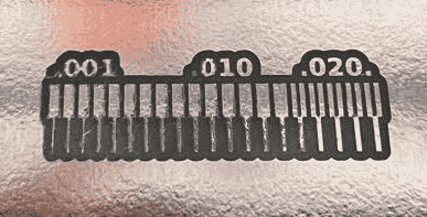
From the result, I think thickness on 0.016inch which almost 0.4mm is enough in general, but if we have a components that needs high current, maybe we could make the traces thicker.
Individual assignment
Please note that, videos in this page may not working on safari browser, in this case you may try another browser.
For the individual assignment, I am planing to make a pcb to control a motor with pushbutton, so before starting with eagle, and as a result of the discussion with my instructor Emma, I need the following components for my circuit:
1- Esp32 wroom as a MCU.
2- 2*2 pinhead connectors.
3- Mosfet.
4- Diode.
5- Pushbutton.
6- External Motor.
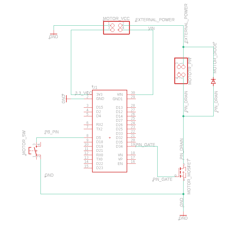
Following the same procedure on Week4, I added all the components and then connected them as shown below:
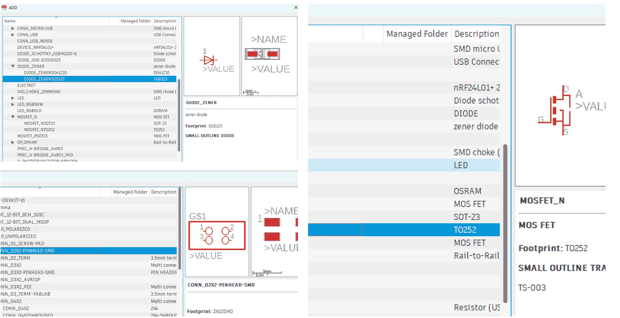
The connected schematic are shown below:
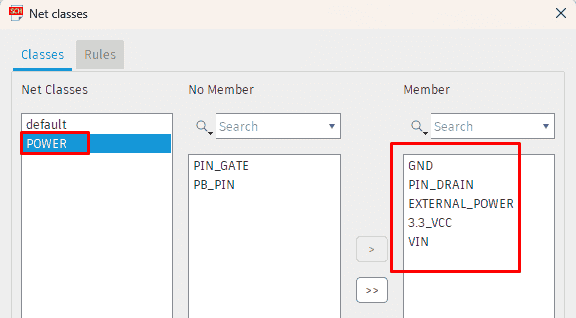
Before switching to board, I navigated to Edit > Net classes > then I added a new net class called power, and add the following members:
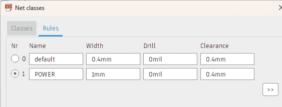
I add those rules:
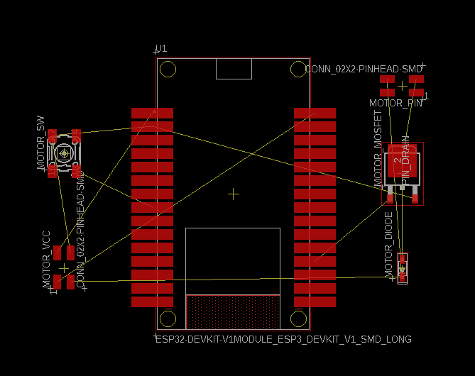
After switching to board, I had to move and arrange all components:
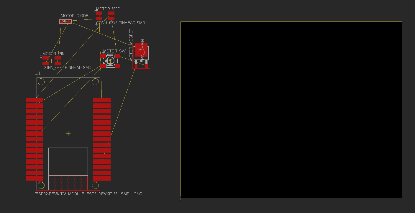
The arranged components:
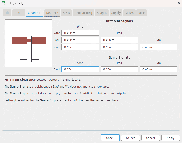
I navigated to view > DRC(design rules) > Clearance and I changed the values to 0.45:
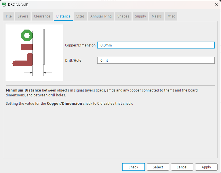
Then from distance tab I set the value of dimension as shown below:
To add routes, from autorouter tool, I set layer 1 only, then it showed different ways, I selected route number 4 as shown below, then I pressed on end job:

I added my nickname to the board,The result of the traces are shown below:
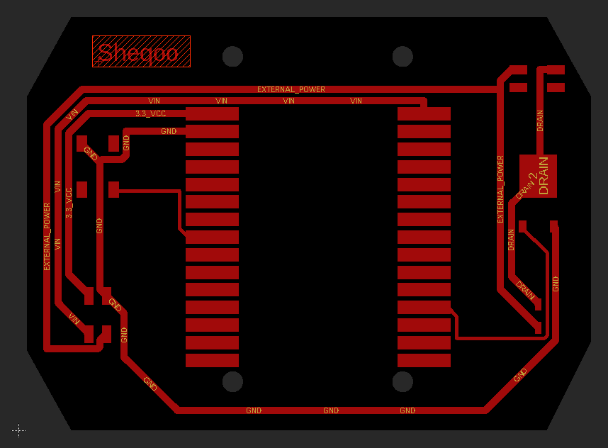
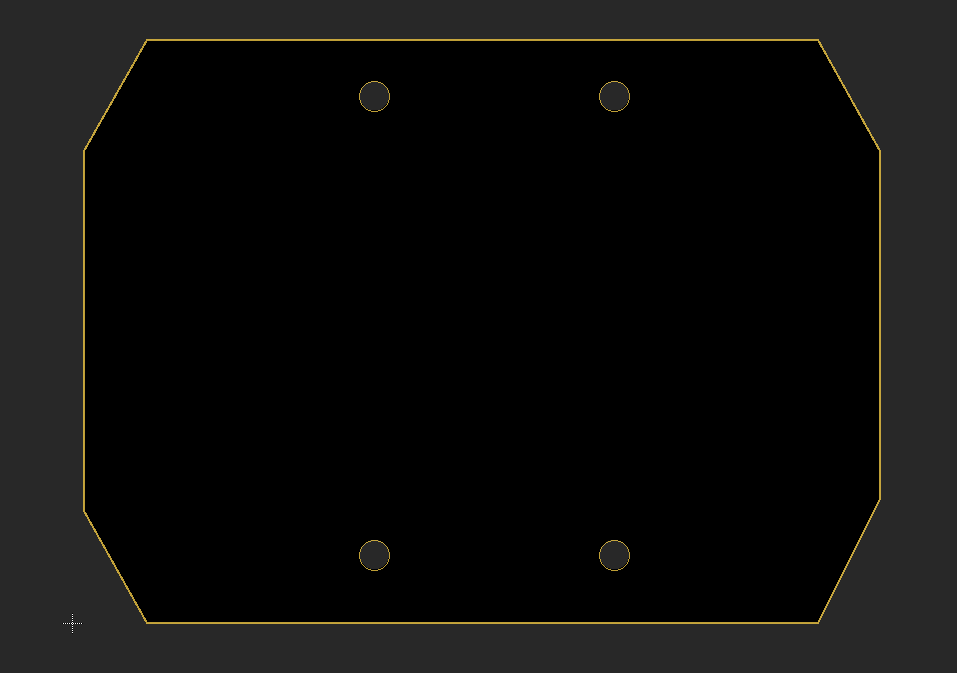
To make the outer shape, from layers, I selected the dimension layer, then by using line command I make a chamfered edge box around the board:
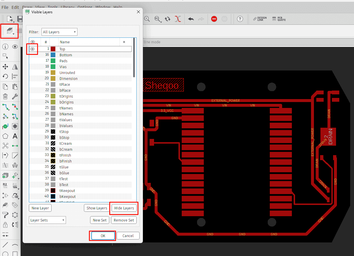
In order to export the png files, for traces; from layers, I hided all layers and make the layer 1 only visible by clicking on the eye beside the layer:
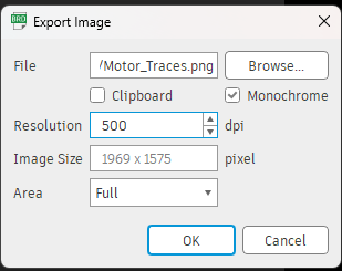
Now from file > export >image > set dpi as 500 with monochrome and full area and choose the file location then ok:
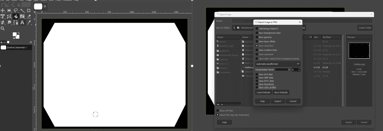
After exporting the png file of the outline, I need to make the inside white so I used the selecting tool as I showed on week 2 then using the bucket fill tool i filled the inside with white and exported it as png file:
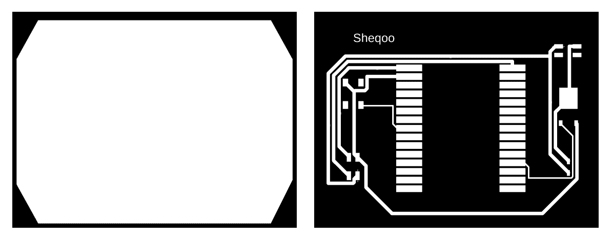
The exported images for both traces and outline are shown below:
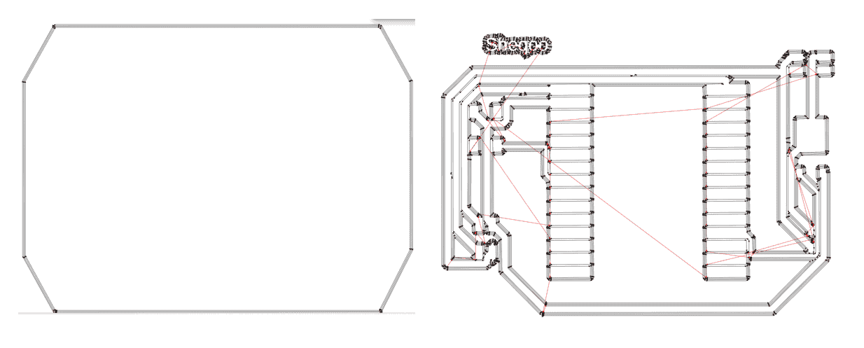
Now, I prepared the traces and outline following the same process and settings for both mill and outline that mentioned above, the tool path for both:
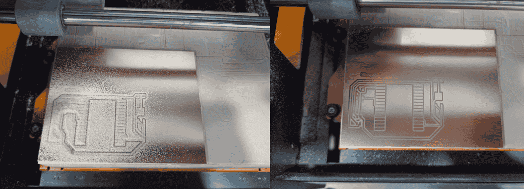
After saving the toolpath, I checked the extension of the file, it should be .rml, then I went to vpanel then pressed on cut, and choose the file and then I clicked on the output as shown below:

The video below shows the cutting operation:
The result of milling thr traces:
To cut the outline, I did the same process, but unluckily the cut was not through so I checked the cut depth and recut the outline:
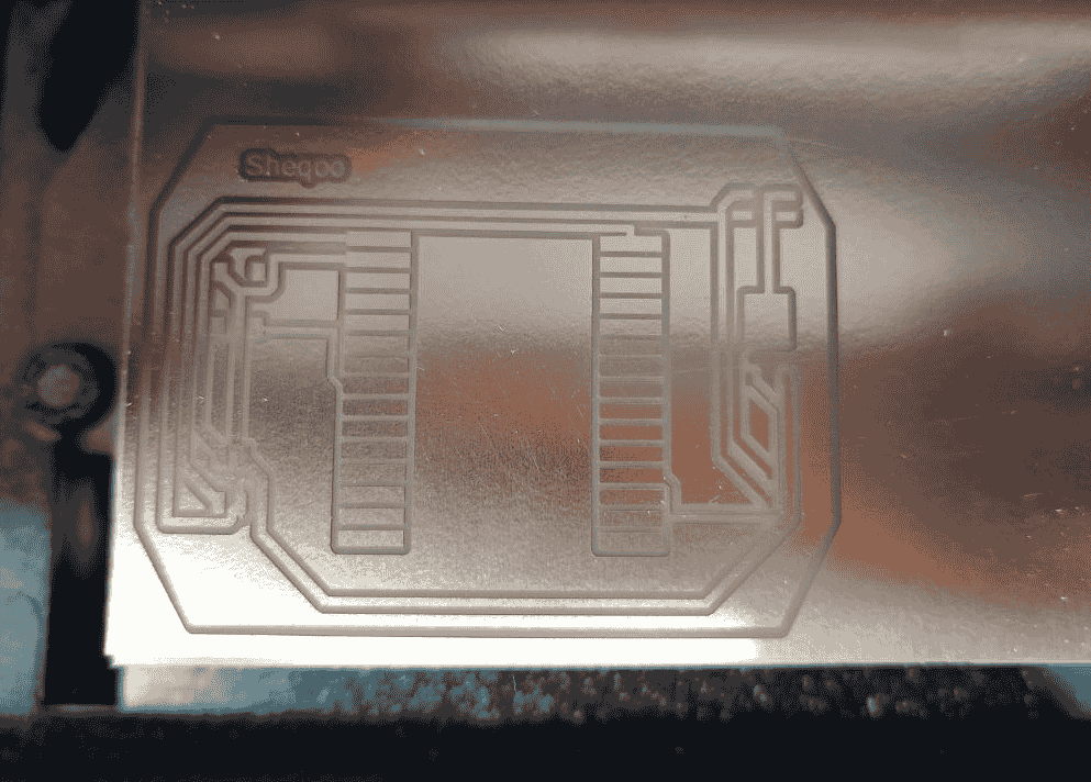
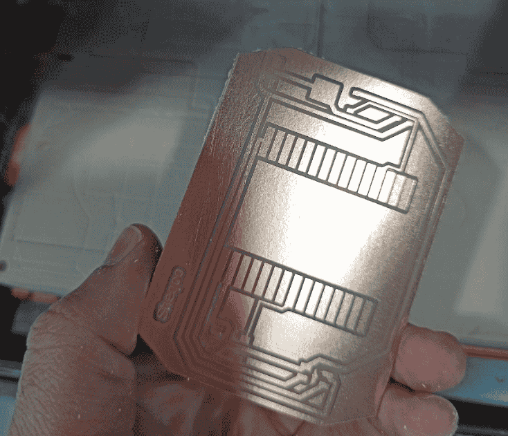
After re cutting, the result was great!
To start soldering the components, first I prepared all of them, then I attached the pins to the development kit, this will help to keep the pins straight while soldering:
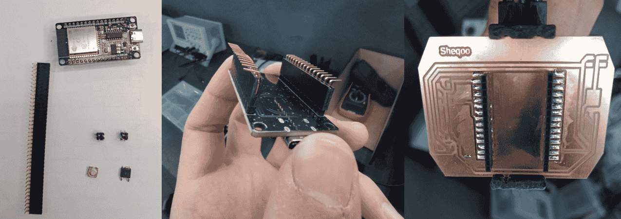
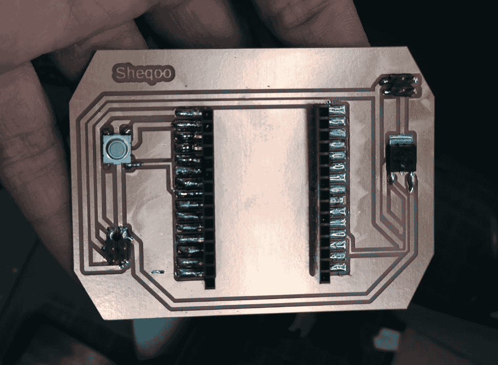
Then I completed the other parts ash shown below:
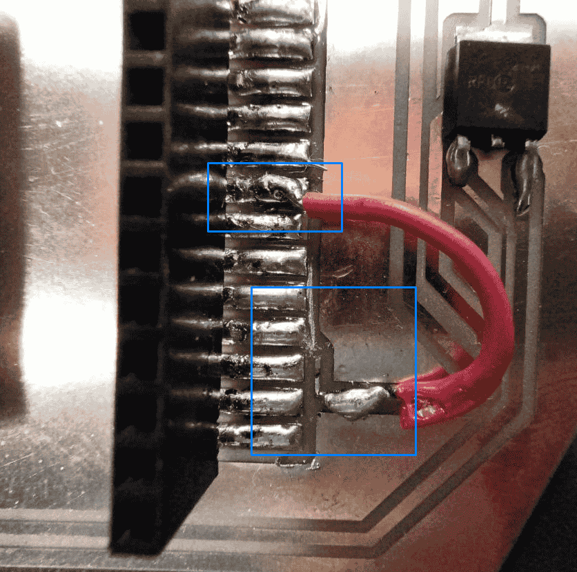
I faced a problem that I realized I'm using an input pin only(pin 35) as an output so I cut the trace using a cutting knife, then welded a wire between the trace and pin 25 that warks as input/output pin:
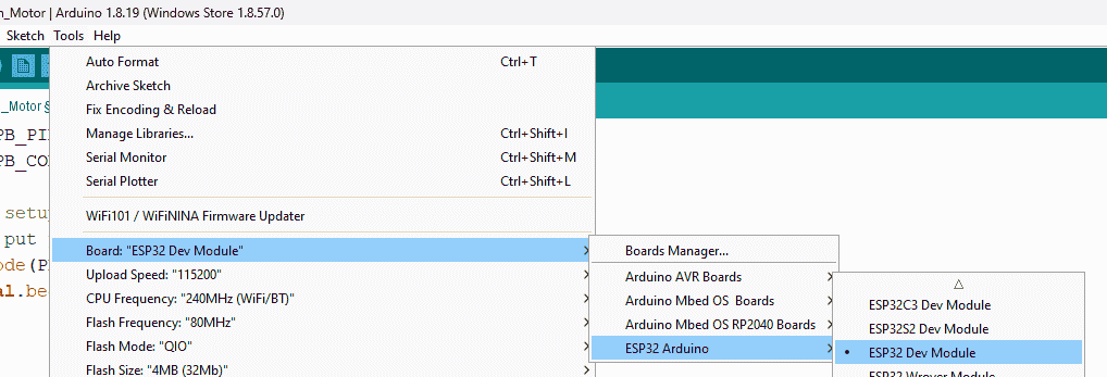
After soldering, and as my instructor advised, I will start to check the push button part and the motor part separately, and to do the push button test, I connected the board to my laptop, and following the same procedure on Week 4, I opened the IDE, then selected the board and the port and wrote the following code:
Choosing Board:
The code:
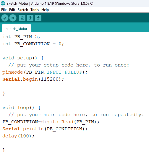
Testing the code, Please note that, if the video you may try another browser.
After testing the push button, now I will test the motor, I wrote the following code for testing:
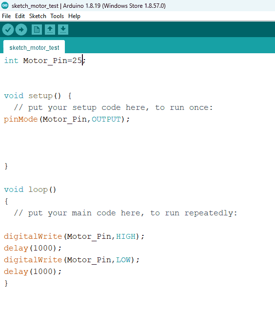
Testing the code:
After testing booth components, I wrote the following code then uploaded it to the board:
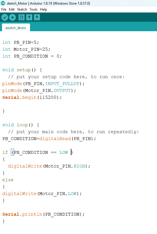
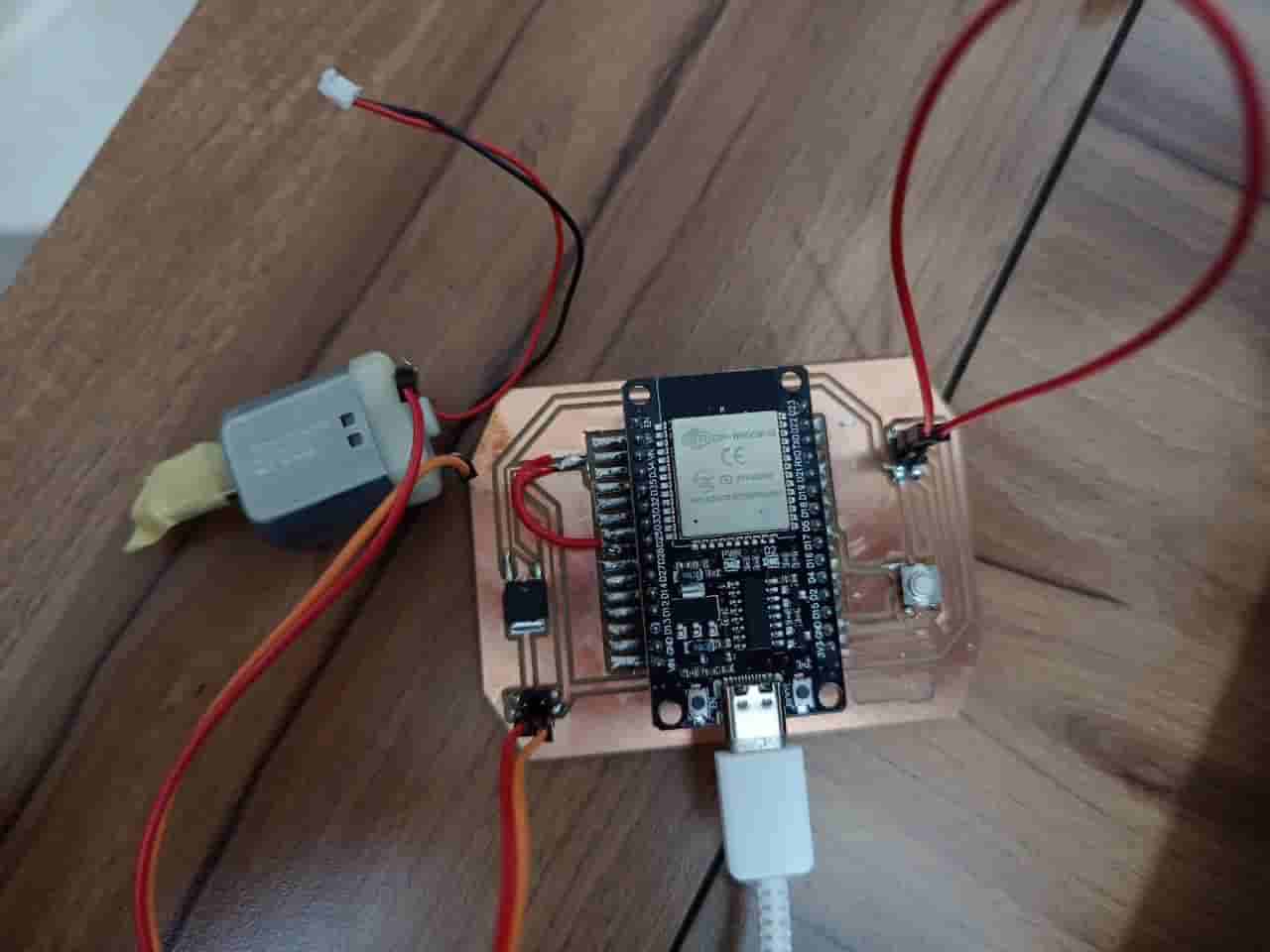
Final test:
