Computer-Controlled Machining
Group assignment
- Complete your lab's safety training
- Test runout, alignment, fixturing, speeds, feeds, materials and toolpaths for your machine
-
Document your work to the group work page and reflect on your individual page what you learned.
To ensure the safety of both ourselves and the laboratory, it is important to adhere to the safety instructions before operating any machine. The essential guidelines for using the CNC machine are highlighted in the following signs:

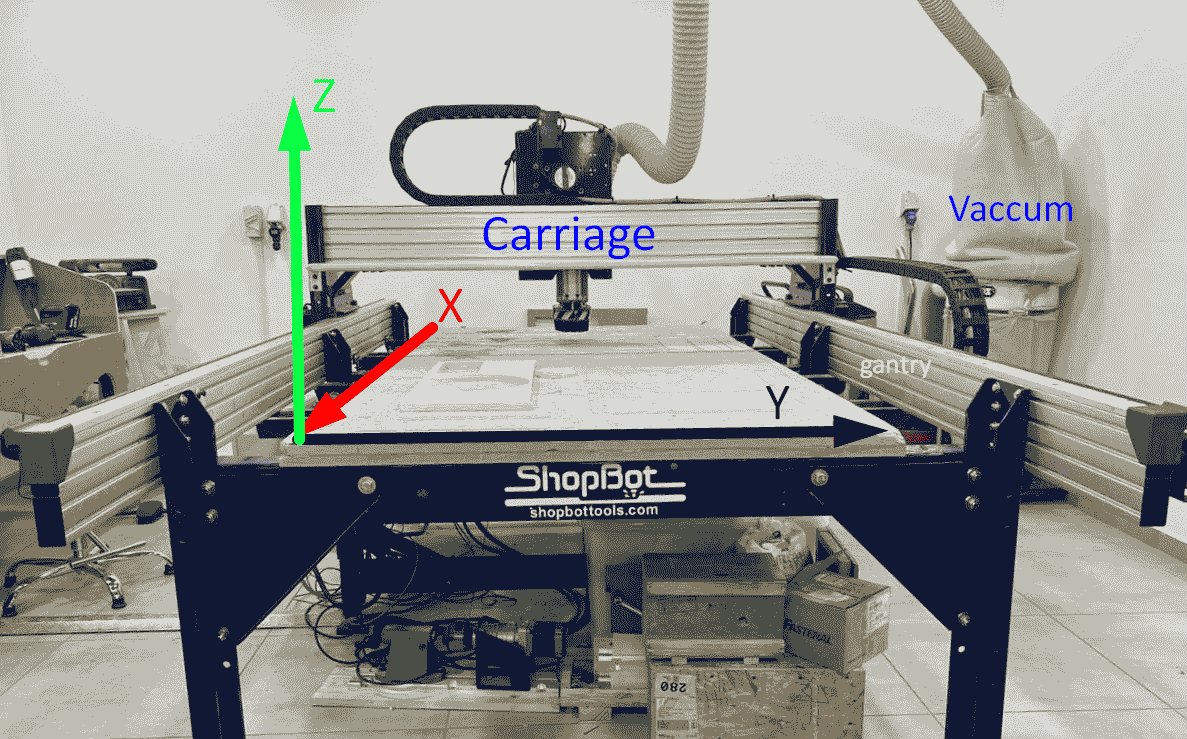
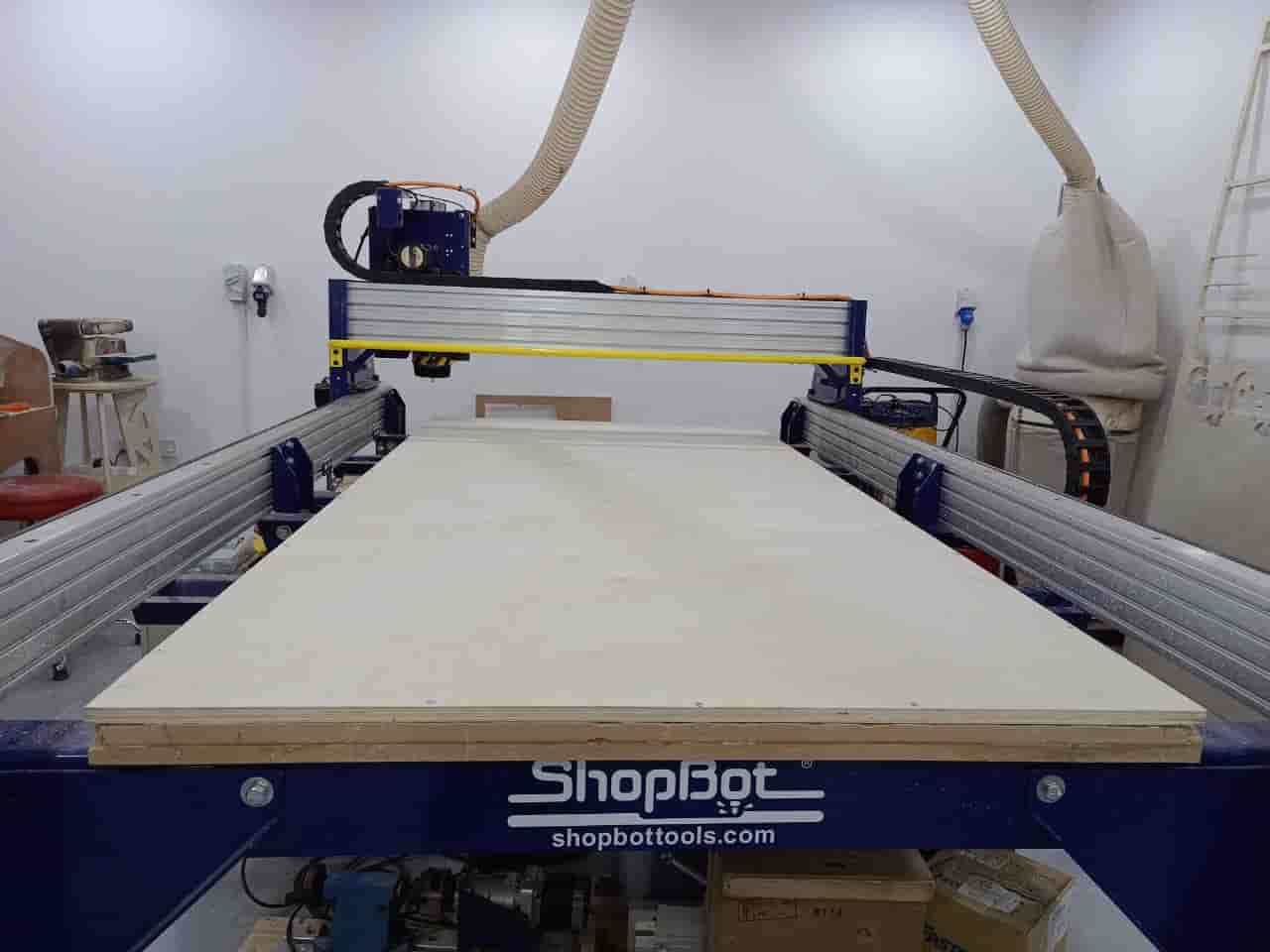
Here in TechWorks we have ShopBot PRSalpha ATC 96-60-8 it comes with working Area (Length x Width x Plunge): 105” x 61” x 8” (2.67m x 1.55m x .2m) - XY Moving Speed (with full cutting force): Max 5”/second (7m/min) - Z Move Speed (with full cutting force): Max 2”/sec (3m/min) - Step Resolution: 0.0004” (0.010mm) - Spindle RPM: Max 18,000 RPM
The machine axes are shown below:
There are different tools that could be used with CNC machining, different tools, different sizes, different material means each tool could be used to make a certain operation based on the shape, size and tool material
Here in TechWorks, we used different types of tools, but mainly there are tools used only for drilling operation and should not be used in milling because it does not have a sharp edges on there flutes, on the other hand the endmills could be used to drill and mill.
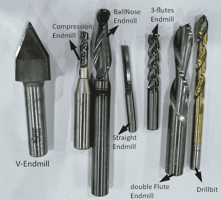
Each Endmill have different settings to deal with, this data could be provided by the tool manufacture as an example we used Onsrud tools, and each material has it own cut settings. the most important settings are number of flutes, feed rate, chip load and the RPM.
To calculate Feeds and speeds, there is a useful calculator called fswizard which from it I could calculate the values based on the following settings:
1- Tool type: like flat endmills or ball-nose endmill.
2- Tool diameter.
3- Tool coated or not.
4- Angle of the flutes, if it has helix shape or it just flat endmill.
5- Length of the flutes.
6- Shank diameter, which is sometimes equal to the tool diameter and sometimes bigger.
7- chip load which is the thickness of the material removed while cutting and this value usually from the tool manufacturer.
8- Rpm which is the rotation speed per minute and for ShopBot maximum rpm is 18000.
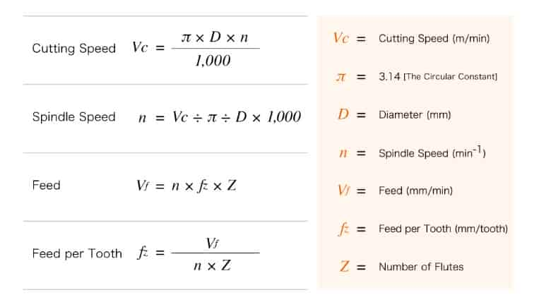
The feeds and speeds also could be calculated from the following equations:
After we completed the safety training, and learned about tools and the machine, we also tested the followings:
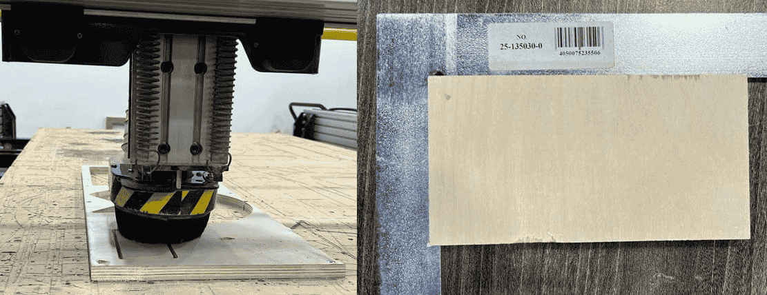
1- We learned how to fix the wood board with screws on the sacrifice bed.
2- After cutting we measured the alignment and it was accurately aligned with sharp 90 degree angle on the corners.
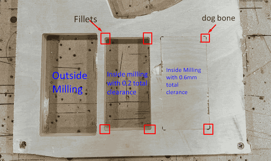
For the clearance we tested the followings:
1- With outside milling, we got a rectangle with accurate dimensions compared to the design.
2- With inside milling and clearance 0.1mm, the corners were had a fillet, this fillet equal to the tool radius, so we could not place the rectangle that we got by outside milling.
3- With inside milling and 0.6 clearance each side with 0.6mm on height and 0.6mm on width also with dog bone, we make it and we could put the rectangle in.
Conclusion
1- It is important when dealing the CNC machine to follow the safety instructions, and do not leave the machine while it is running.
2- The proper fixturing of the board, is important to have safe cut, otherwise the tool could be broken, or an injuries to the operator and a damage to the machine could happened.
3- Running time of the machine depends on the complexity and the size of the desired job.
4- When measured the size of the rectangle after cutting, it had very accurate dimensions compared with the design with a 0.0(X)mm error, this means that the machine capable to mill precise parts.
individual assignment:
CAD and CAM
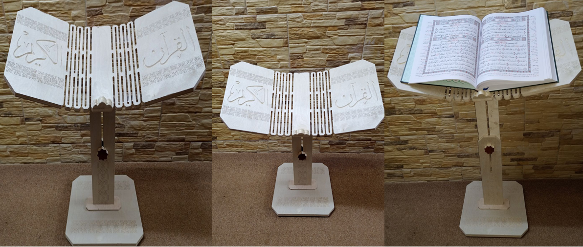
For the individual assignment I used Fusion 360 to Design a "Quran Stand", which will help us and especially the elderly, to read the book easily. It has a special advantage: the height adjustment to set the proper height of viewing and reading.
Before designing, I get inspired from different available products in the market, but all of them had 2 pieces to hold the book on angle, but I decided to make it one part with living hinges, with simple and practical design.
I started with making a base then the front and back support, I learned how to add screws and nuts ,I have added them so I could design the two knobs based on the exact size, then I sketched the book base and I added living hinges so it could bend easily.
After I finished the design, I saved all components as dxf file as I mentioned on Week 3, for the book, bottom base and the front support to add the Islamic pattern on them.
The Islamic patterns are an Islamic art which is based on the belief that geometry reflects the underlying order of the universe, and that the repetition of geometric forms creates a sense of harmony and balance. Islamic patterns are admired for their intricate beauty, spiritual symbolism, and cultural significance.
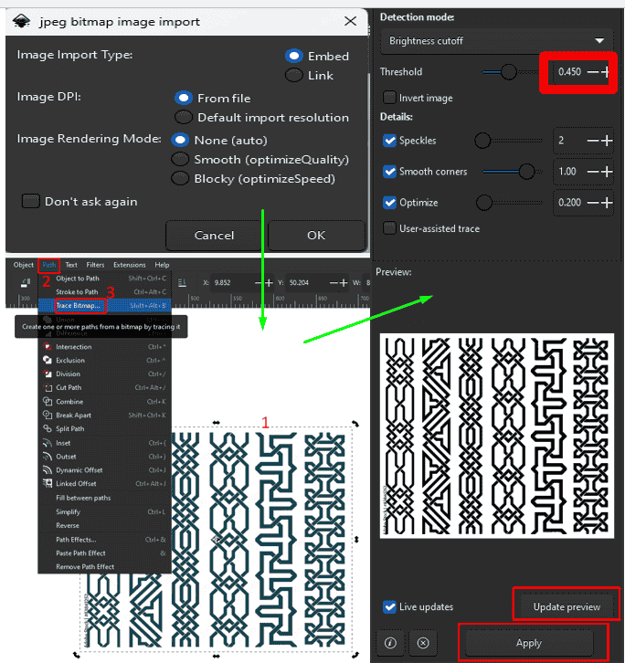
Now using inkscape, and after I downloaded the picture of the pattern, I imported and selected the picture > navigated to path > Trace Bitmap then from threshold I controlled the contrast on the traced object then > update preview > apply. After That I saved the file as svg:
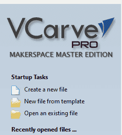
After I saved all DXF and Svg files , Now I had to prepare them to send them to the machine, and to do this, we use a VCarve Software which is a CAD/CAM software used either to draw or to prepare the drawings to send to the machine.
When I opened the software it asks me to create a new file or go with an existing file or project, In my case I went with create new file.
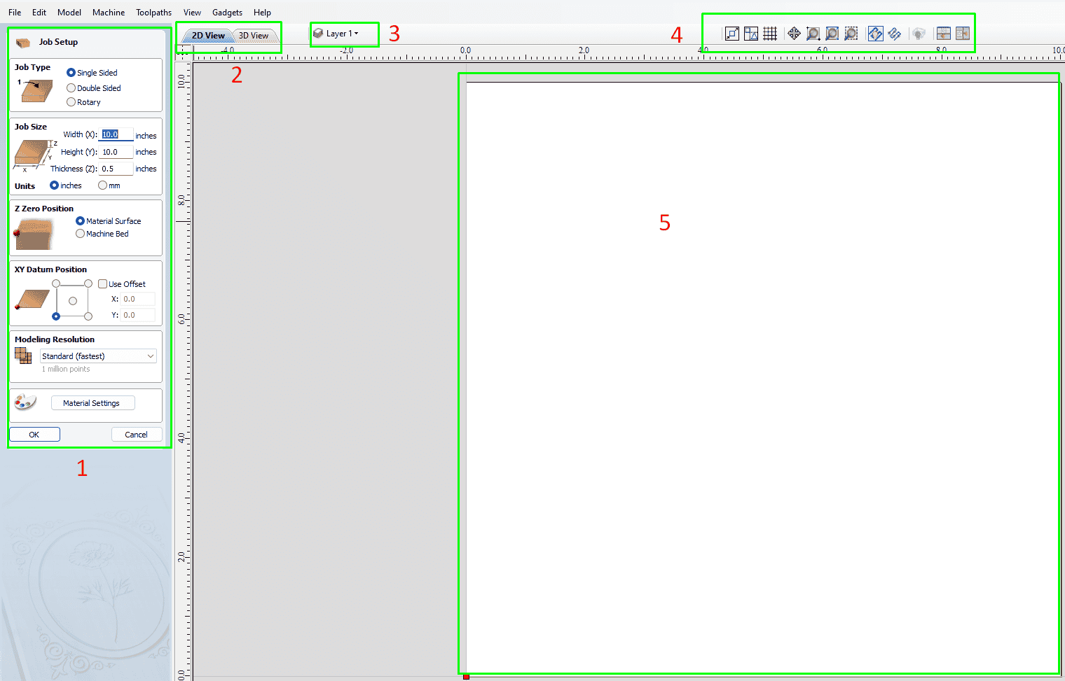
After creating a new file, now I had to set the job specification. There are a mainly five sections:
1- Jop setup: In this section I choose the job type as it on one side or both or even rotating. Also I define the job size, the standard size of the wood board are 2440mm height with 1220 mm width, and for thickness I chose 18 mm. For modelling resolution it's important to preview the toolpath before cutting.
2- Where I can switch between 2D and 3D view.
3- Where I can view or hide layers, each layer could contain different elements.
4- Tool bar.
5- Sketches canvas.
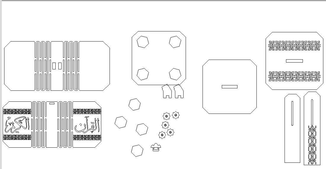
All shapes after importing:
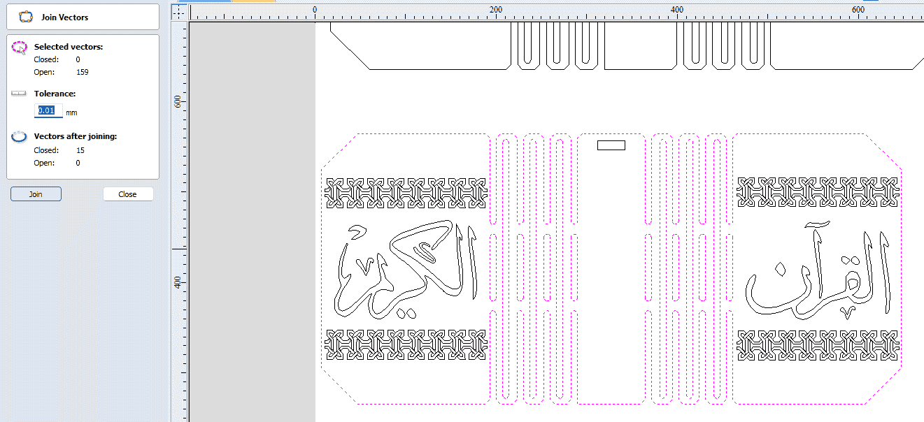
In order to make sure that all shapes closed, I used join command, I selected all pieces then select tolerance to be 0.01:
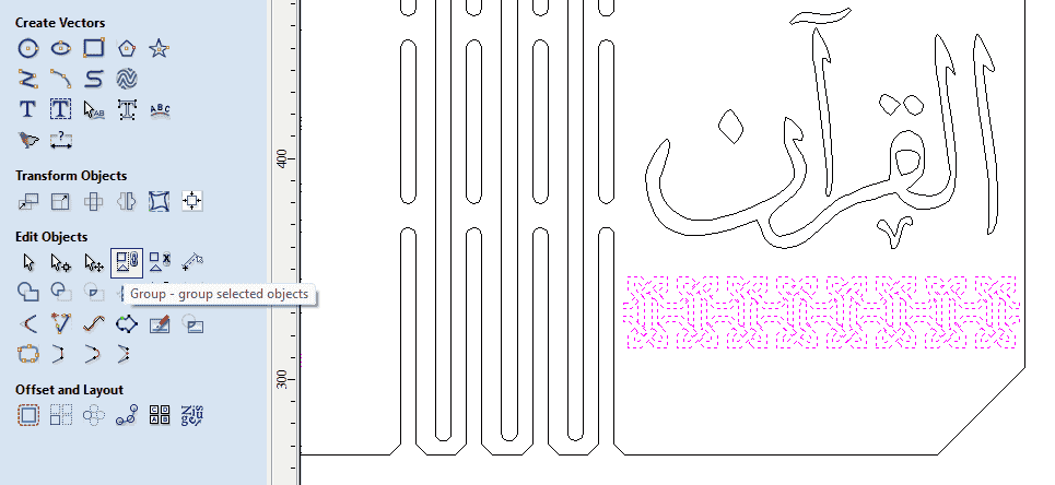
After Joining all curves, grouping the shapes will help to arrange them and saves a lot of time, so I have selected the shapes that I want to group then I pressed on group option:
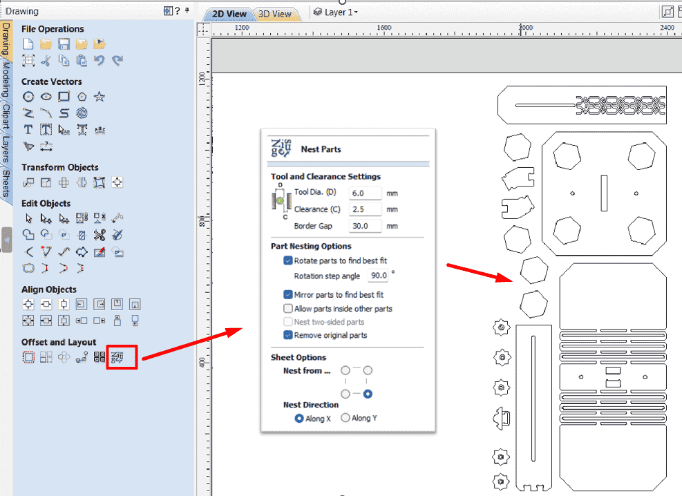
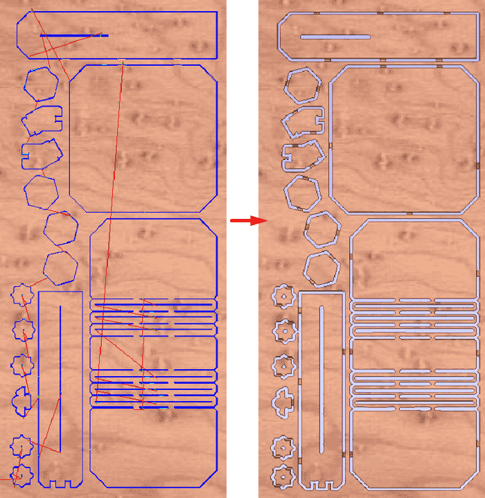
Now to arrange all models , I used Nesting tool, border gap is the distance between the edge of the board and the parts, while the clearance is the space between nested parts with keeping all other parameters as default, then I clicked on preview to see the nesting, then I pressed on OK:
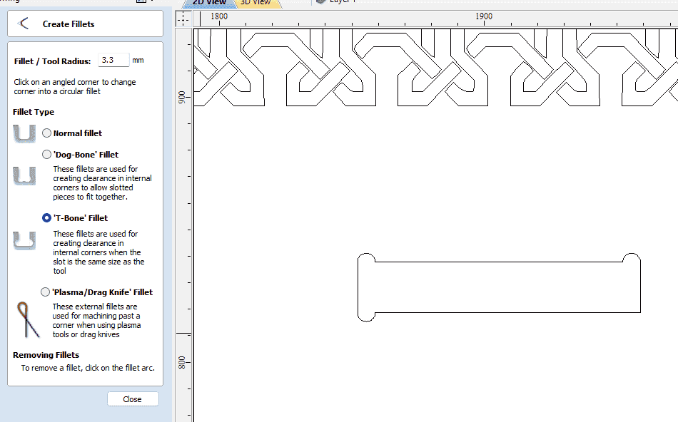
Because the tool has a diameter, it can not make the sharp edges, so the assembly will not occur correctly, I tried to make the T bones on the corner while designing using fusion, but from VCarve it was easier, I navigated to create fillet > selected tool radius > T-Bone > select the corner of the shape as shown below:
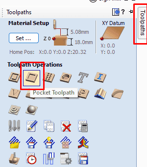
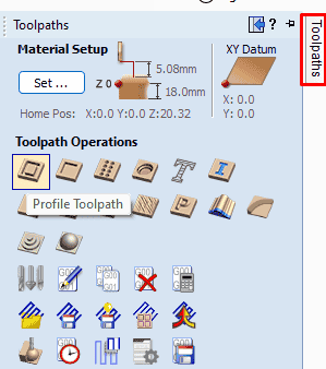
Now all pieces are ready to be prepared for milling, I navigated to toolpath on the right top corner, I chose pocket operation:
The start depth will be from the top of the board so it will be zero, while the cut depth was 8mm:
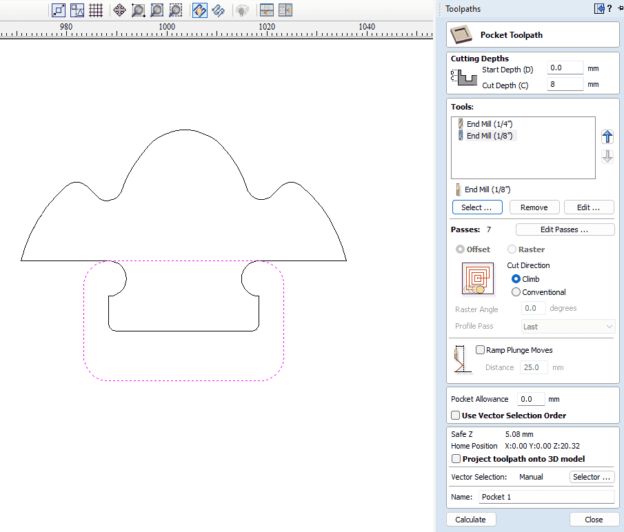
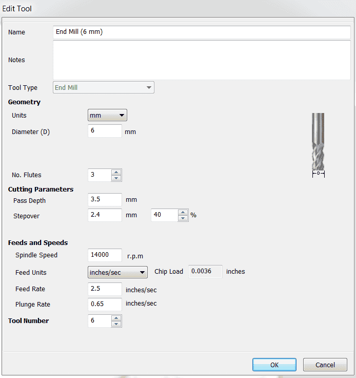
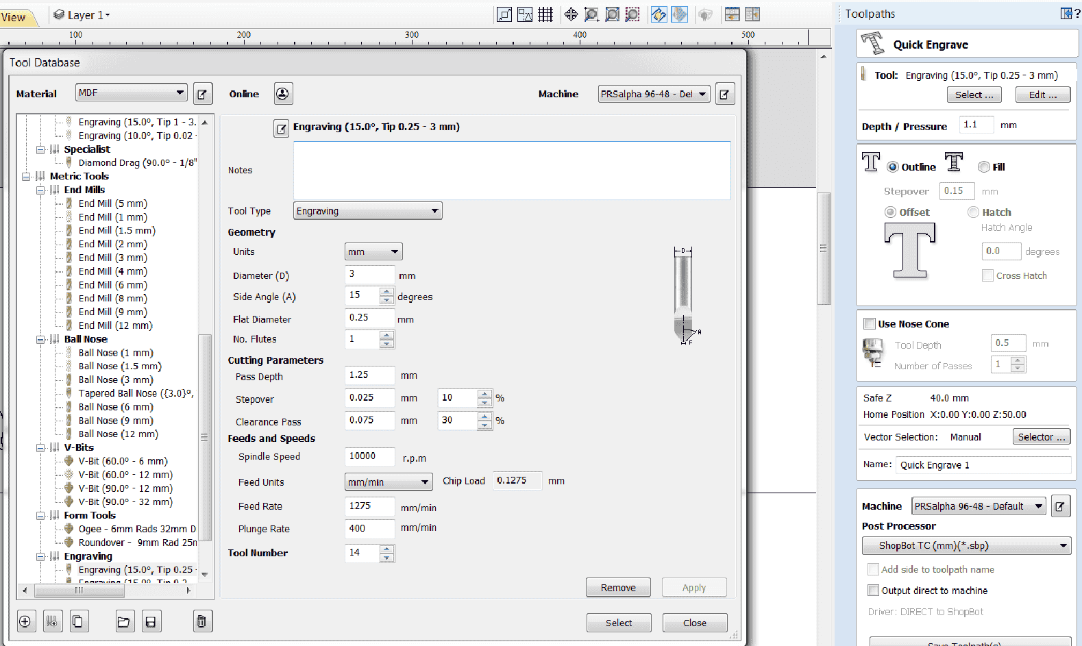
then I clicked on the select tool, I chose the 6mm tool with the following values:
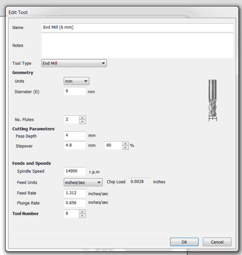
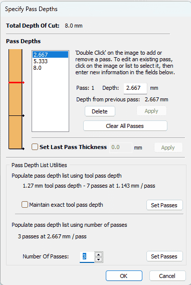
Milling could not be done with one pass at thick material, so the number of passes I set it to 3 passes, and the software will divide the cut depth on the number of passes:
For the pocket allowance, I set the value 0.3 so it will be 0.6 total and that is the result we have from the group assignment, while the ramp value was 20 (tool will move as a ramping while the z height goes lower) , with 50 mm safe z(retraction distance when homing), then press on calculating.
Because I have different pockets with different depth, I followed the same procedure for other pockets with same tool, passes, ramp and safe z value, the result of the pockets were as shown below:
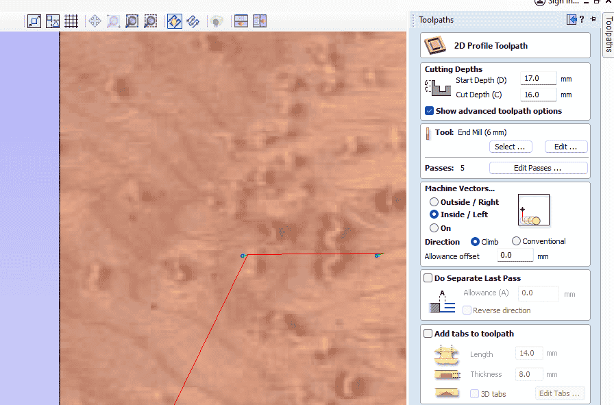
For the profile, I have selected all pieces then from the tool path I selected profile:
The cut depth was 18.5mm to make sure the cut will be through for all pieces, with same tool diameter and 5 passes, milling will be outside, that means the tool will move on the outside path with for sure a ramp angle:
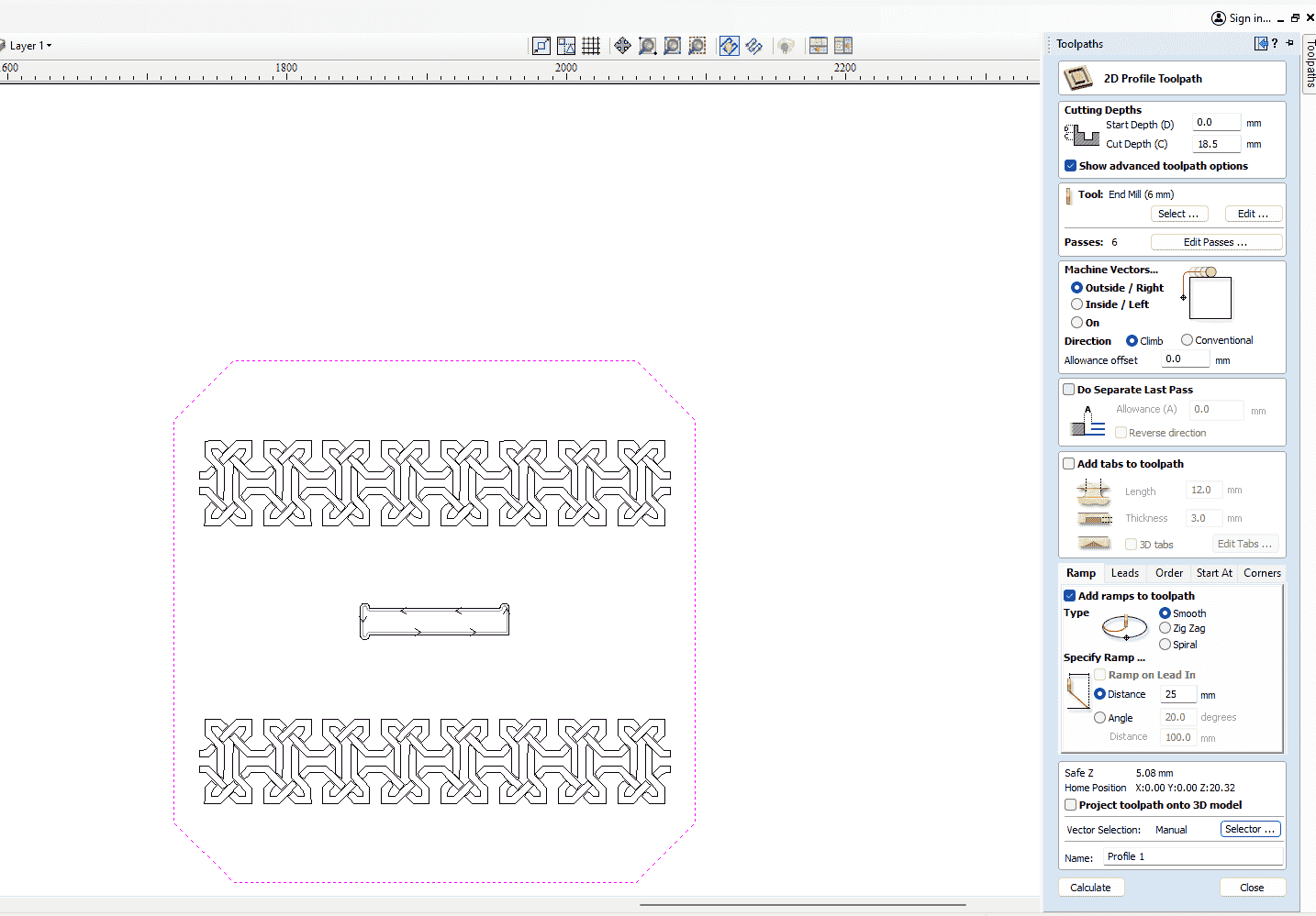
The tool settings for the profile are shown below:
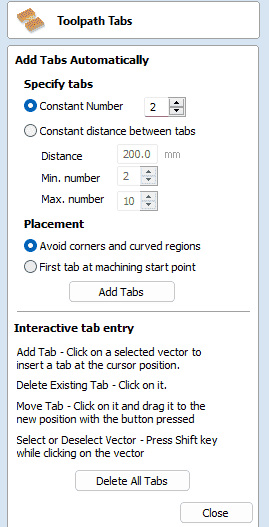
It's important when cutting the material with full depth to add tabs that will hold the pieces on place, if it was not fixed it will move when the tool moves and will make a hazard even for the tool or the machine and the most important for the machine operator, to add tabs I clicked on att tabs to tool path, I set thickness and height of the tab then navigated to edit tabs, either it could be adding tabs manually of automatically.
To add tabs automatically, I selected all shapes, then added number of tabs on each shape, it could be to add some conditions like fixed distance between tabs, avoid corners. Then I pressed on add tabs then close:
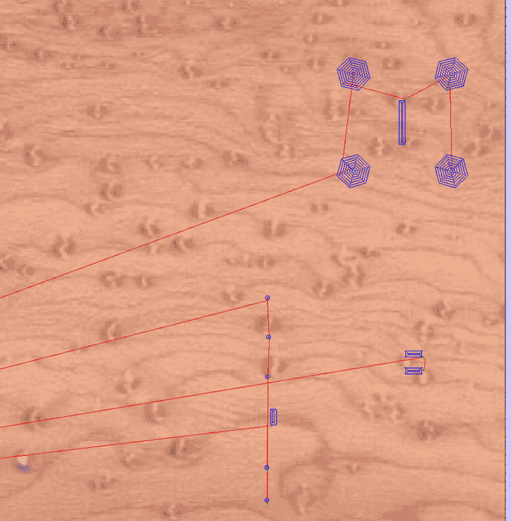
The result of adding the tabs:
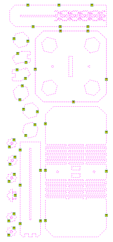
After finishing the settings of the cutting, I calculated the toolpath, the final calculation is shown below:
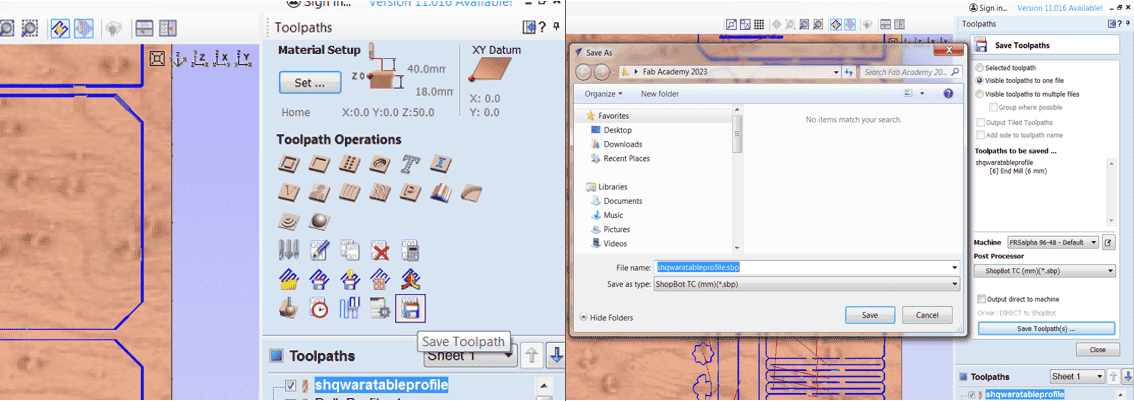
Now all files are ready, to save them, I checked on the toolpath box then I clicked on save tool path > choose a folder > save.
After saving all toolpaths and saving them, now I am ready to prepare the machine for cutting!
Board and machine preparing
First thing we should follow before installing the wood board is to make sure that the sacrifice board ar clean in order to make sure no obstacles that prevent the board to be flat, after cleaning, of course with help of my colleagues we putted the board on the table, then with screws I fixed the wood board:
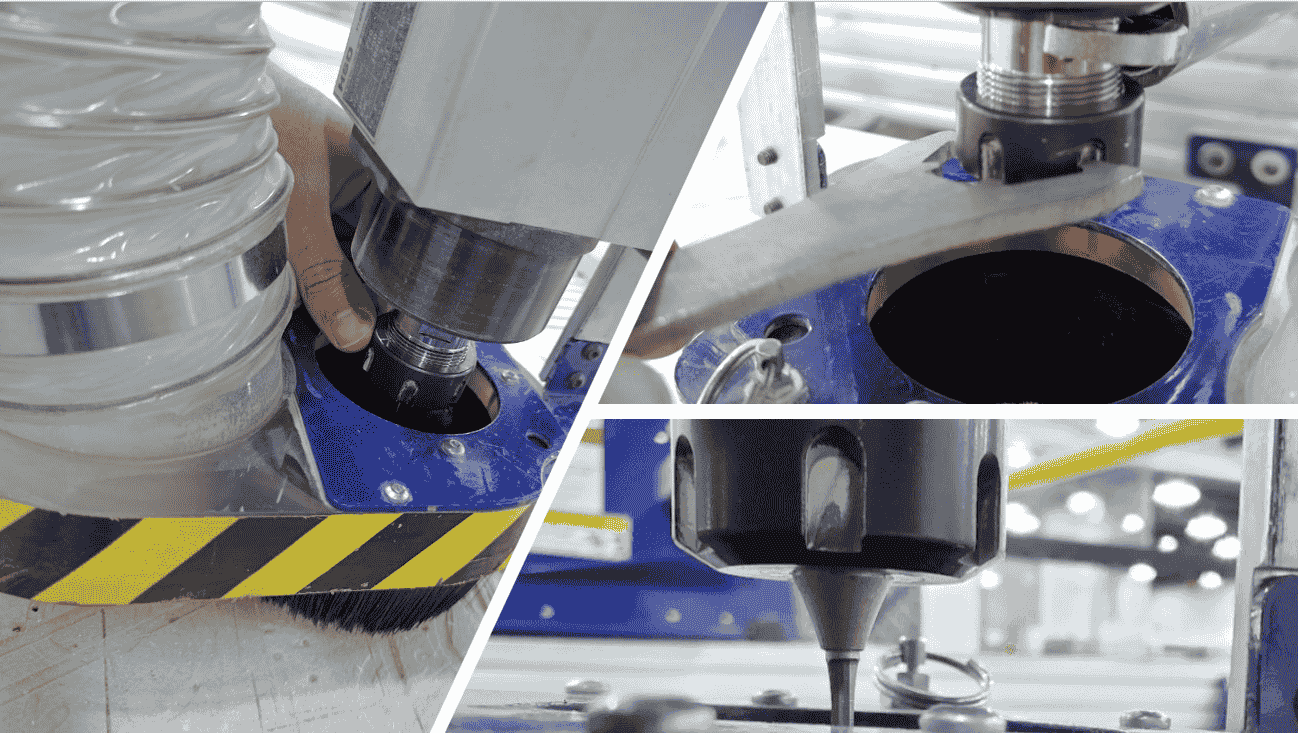
To put the 6mm cutting tool I unscrew the collet of the milling head, I placed the tool then tightened the collet again:
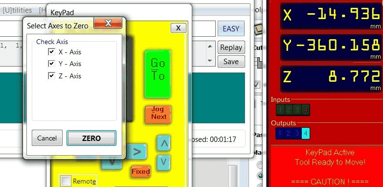
After preparing the board and tool, there is still last thing to do and that is zeroing the axes, x,y,z and to do this, I opened the machine control software then using arrows keys on keyboard I moved the spindle to to the x,y zero of the machine then I started to move the spindle down until the tool touches the top surface of the board, then pressed on zero axis> checked all of the axes > pressed on zero:
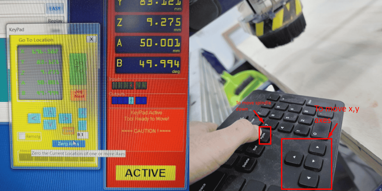
The video below shows the procedure of zeroing the z-axis, as I kept moving down the spindle util it reaches the paper:
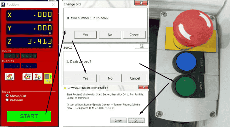
After the tool reaches the paper, Now I can set the z axis as zero as shown below:
Now the machine is ready to be used. To run the pocket and the profile. from control software, I clicked on cut part, then I chose the file > press enter> the software will ask if the tool number is correct > z axis is zeroed > press on start button > press ok:
The machine now starts cutting, I make sure the vacuum are on then I staid monitoring, if I want to stop the machine I press on space bar or incase I needed to press on stop button:
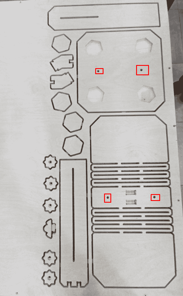
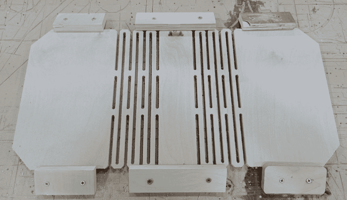
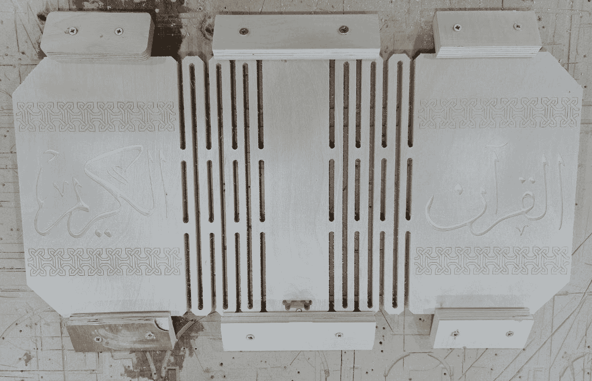
After the machine finished the pockets and profiles tool path, the result are shown below, note that I made the 4 holes(that are not through) so I can flip the pieces in the following steps:
In order to make sure that the pieces will be straight after flipping, I make two holes in the sacrifice bed with the following settings, note it starts from 17mm depth not from zero:
After that I put two sticks in the holes then flipped the piece and fix it to the sacrifice bed:
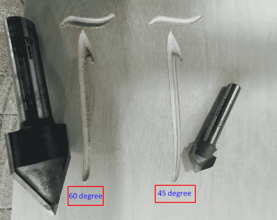
To make an engrave for the pattern and the words I used different two tools, but firs I wanted to check how the shape will looks like with those tools so I make a test with 60 and 45 angle tools with the same tool settings except the angle:
The result of the booth tests are shown below:
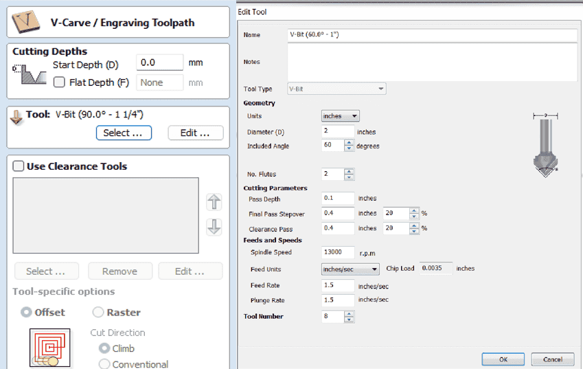
For the pattern also I tested both the 45 degree v-bit and the engraving bit, the engrave settings as shown below:
The result of the testing:
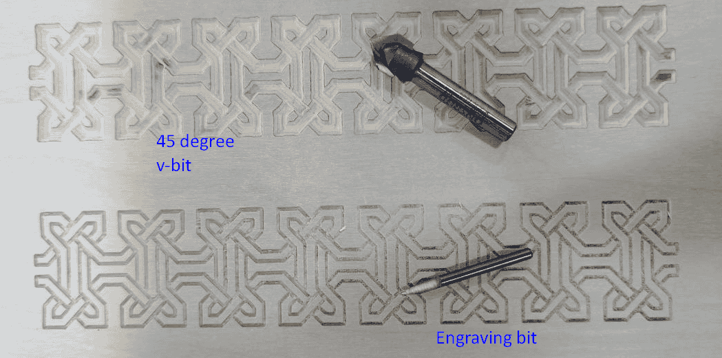
As a result, I will go with 45 degree v-bit for the letters and the engraving bit for the pattern:
I did the same process for the base after that I trimmed the parts from the board to be assembled, but still before the I started to assemble pieces, in order to keep the hinges with angle, I made a fixture around the piece, then using two pieces of acrylic, I heated them with heat gun so they will take the shape, then I fixed them with screws:
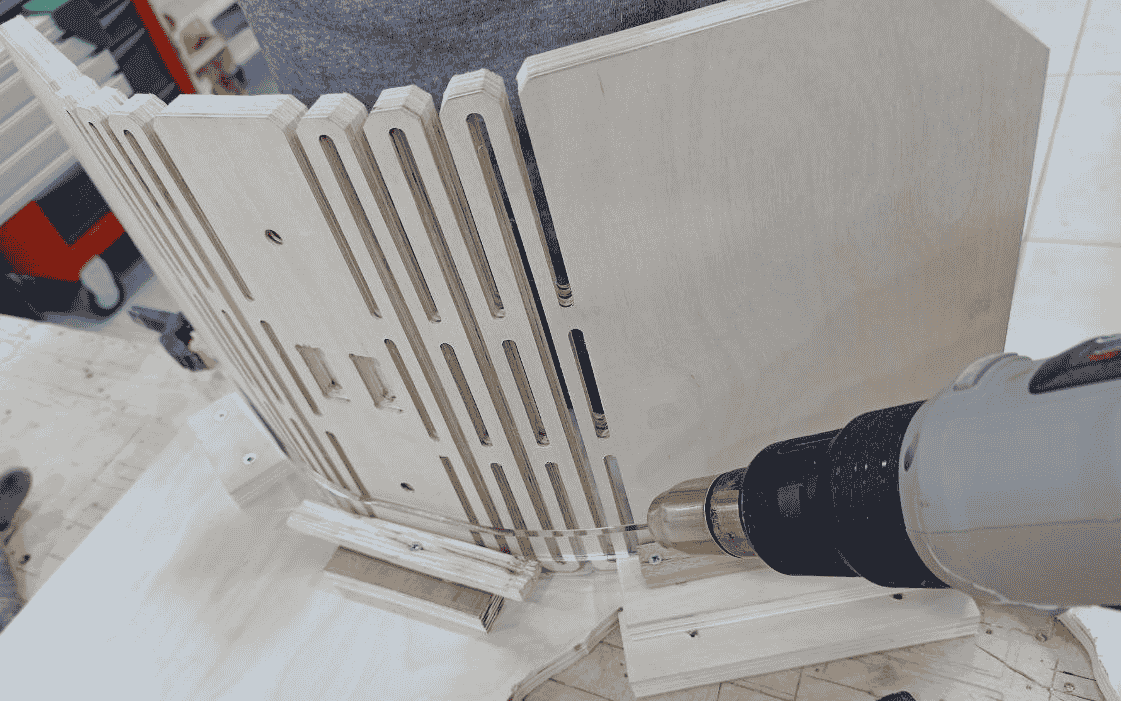
After fixing the angle I started to assemble the parts, first I assembled the base then I putted the first support, the pressift was great but for safety I added some glue, then I assembled the book handler with the two support, finally I put nut and screw to the knobs and assembled them as shown below:
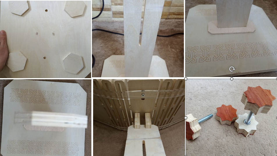
Hero Shots!