Networking & Communications
Group assignment
During Networking and Communications Week in Fab Academy, we embarked on a project to explore various methods of connecting two microcontrollers. Our objective was to establish a wireless communication link between microcontrollers and utilize it to control a LED lighting system. In this documentation, we will focus on our exploration of ESP-NOW, a communication protocol developed by Espressif Systems, and demonstrate how we successfully implemented it in our project.
ESP-NOW is a communication protocol specifically designed for low-power devices, developed by Espressif Systems, the creators of ESP32 microcontrollers. It allows direct communication between devices without the need for a Wi-Fi network or an access point. ESP-NOW operates in two modes: Station (STA) and Soft Access Point (AP).
Howe we implement:
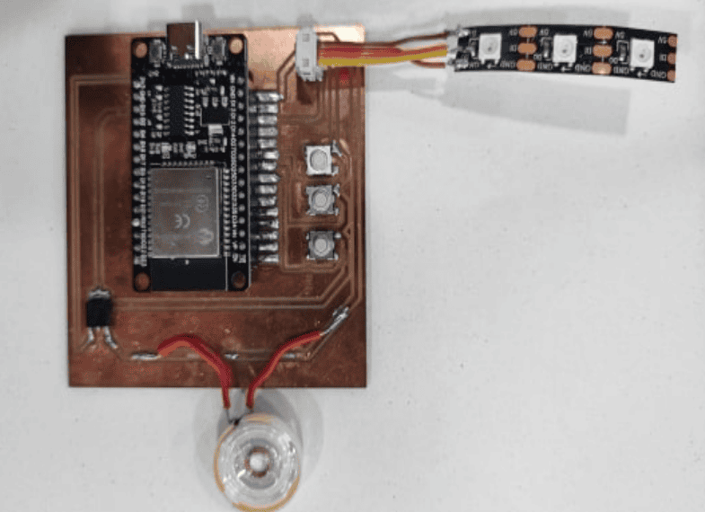
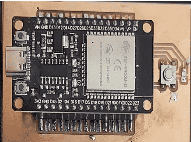
1- Hardware Setup: We connected an ESP32 Dev Kit microcontroller to a push button and a LED. The push button was used as an input to trigger the LED lighting control. Additionally, we had another microcontroller, acting as the receiver, connected to an NeoPixel LED.
2- Configuring ESP-NOW: We set up one ESP32 module as a sender and the other as a receiver. The sender module was configured to send messages via ESP-NOW when the push button was pressed, while the receiver module was set up to receive and interpret these messages.
3- Establishing Communication: The sender module, in STA mode, established a direct connection with the receiver module, operating in AP mode. This allowed for peer-to-peer communication between the two microcontrollers.
4- LED Lighting Control: When the push button was pressed on the sender module, it sent a message via ESP-NOW to the receiver module. The receiver module interpreted the message and controlled the connected LED accordingly, resulting in the desired lighting effect.
The receiver PCB:
The remote PCB:
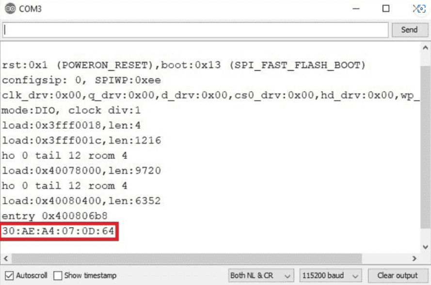
For the remote and receiver we need to figure out the mac number its like an identifier for each MCU using this code:
                #include "WiFi.h"

                void setup(){
                  Serial.begin(115200);
                  WiFi.mode(WIFI_MODE_STA);
                  Serial.println(WiFi.macAddress());
                }

                void loop(){

                }
Now the remote code:
                #include
                #include

                #define PIN_NEO_PIXEL  13  // Arduino pin that connects to NeoPixel
                #define NUM_PIXELS     3   // The number of LEDs (pixels) on NeoPixel

                Adafruit_NeoPixel NeoPixel(NUM_PIXELS, PIN_NEO_PIXEL, NEO_GRB + NEO_KHZ800);

                uint8_t remoteMac[] = {0xB8, 0xD6, 0x1A, 0x5C, 0x03, 0x88};

                void setup() {
                  Serial.begin(115200);
                  NeoPixel.begin();
                  NeoPixel.clear(); // Set all pixel colors to 'off'
                  NeoPixel.show();  // Update the NeoPixel strip

                  WiFi.mode(WIFI_STA);
                  WiFi.disconnect();

                  if (esp_now_init() != ESP_OK) {
                    Serial.println("Error initializing ESP-NOW");
                    return;
                  }

                  esp_now_peer_info_t peerInfo;
                  memset(&peerInfo, 0, sizeof(peerInfo));
                  memcpy(peerInfo.peer_addr, remoteMac, sizeof(remoteMac));
                  peerInfo.channel = 0;
                  peerInfo.encrypt = false;

                  if (esp_now_add_peer(&peerInfo) != ESP_OK) {
                    Serial.println("Failed to add peer");
                    return;
                  }

                  esp_now_register_recv_cb(OnDataRecv);
                }

                void loop() {
                  // No need to add any code here
                }

                void OnDataRecv(const uint8_t* mac, const uint8_t* data, int len) {
                  if (len == 1) {
                    uint8_t receivedData = data[0];
                    handleReceivedData(receivedData);
                  }
                }

                void handleReceivedData(uint8_t data) {
                  if (data == 0) {
                    NeoPixel.clear();
                    NeoPixel.show();
                  } else if (data == 1) {
                    NeoPixel.setPixelColor(0, NeoPixel.Color(255, 0, 0));
                    NeoPixel.show();
                    delay(2000);
                    NeoPixel.clear();
                    NeoPixel.show();
                  } else if (data == 2) {
                    NeoPixel.setPixelColor(1, NeoPixel.Color(125, 125, 0));
                    NeoPixel.show();
                    delay(2000);
                    NeoPixel.clear();
                    NeoPixel.show();
                  } else if (data == 3) {
                    NeoPixel.setPixelColor(2, NeoPixel.Color(125, 80, 200));
                    NeoPixel.show();
                    delay(2000);
                    NeoPixel.clear();
                    NeoPixel.show();
                  }
                }
Conclusion:
Through our exploration of ESP-NOW, we successfully established a wireless communication link between microcontrollers, enabling us to control a LED lighting system. ESP-NOW provided a straightforward and efficient method for peer-to-peer communication without relying on Wi-Fi infrastructure. This project showcases the versatility and potential of ESP-NOW for various applications requiring wireless microcontroller communication.
Individual assignment
For this week I went through different types or ways for communication, it is either wired or wireless communication.
Starting for the wired communication, I will discuss three protocols to communicate through wires:
1- UART (Universal Asynchronous Receiver/Transmitter) :
in this protocol, each device has it is own clock, therefore the data transition are Asynchronous that is means one device should send data and the other should receive data at the same baud rate(send and receive data at the same speed). Before sending the data to the receiver, the transmitter converts this data into individual bits and sending them serially(now that makes to me sense why I define the baud rate as Serial.begin) one by one. Each bit is then sent at a specific baud rate and For example, if the baud rate is set to 9600, each bit would be transmitted for approximately 104 microseconds (1/9600 seconds).The receiver on the other end reads each bit as it arrives and reconstructs the original data format.

In order to ensure accurate data transmission, UART has a frame format. The frame typically consists of a start bit, data bits, an optional parity bit, and one or more stop bits. The start bit is always a low-level signal, which indicates the beginning of a frame. The data bits are the actual information being transmitted and can range from 5 to 9 bits depending on the configuration. The optional parity bit is used for error detection and can be even, odd, or none. Finally, the stop bit is a high-level signal, which marks the end of a frame.

2- SPI (Serial Peripheral Interface) :
in this protocol, data can be transmitted and received simultaneously. The communication is initiated by a master device, which generates a clock signal and selects the slave device to communicate with. The slave device responds to the master's requests and sends back the data. More than one slave could be connected to the master, the number depends on different factors one of them is the number of the SS pins of the master(Slave Select) or sometimes called CS(Chip Select) those pins used to select the slave device with which the master wants to communicate. The master device sends a low signal on the SS pin of the selected slave device to initiate the communication and sends a high signal to deselect the slave device once the communication is complete.
The other three terminals of the SPI protocol are the MOSI (Master Out Slave In) which is a line through which the master device sends data to the slave device. This line is unidirectional and always driven by the master device while the second one is the MISO (Master In Slave Out) which is a line through which the slave device sends data back to the master device. This line is also unidirectional and always driven by the slave device. Last one is the SCLK (Serial Clock) which is a line used to synchronize the transfer of data between the master and slave devices. The master device generates the clock signal and sends it to the slave device.
So the SS is the signal used to select the specific slave device for communication. While together, MOSI and MISO form a bidirectional communication channel between the master and the slave device, while the SCLK signal provides the timing information to ensure proper data transfer. The MOSI, MISO, and SCLK signals are also sometimes referred to as the "SDO" (Serial Data Out), "SDI" (Serial Data In), and "SCK" (Serial Clock) signals, respectively.

By having a frame structure, SPI can ensure that data is transferred accurately and without any errors.The frame consists of four signals: the Serial Clock (SCK), Chip Select (CS), Master Output, Slave Input (MOSI), and Master Input, Slave Output (MISO). The SCK signal acts as a clock, synchronizing the transfer of data between the master and slave. The CS signal selects which slave device is being addressed. MOSI and MISO are the data lines used to send and receive data between the devices.
.png)
3- I2C (Inter-Integrated Circuit) :
The I2C protocol is often preferred over SPI when there are multiple slave devices that need to be connected to the same bus(the communication channel or medium over which data is transmitted). This is because I2C uses a two-wire interface, consisting of a clock line (SCL) and a data line (SDA), that can be shared by multiple slave devices, whereas SPI typically requires a separate slave select line (SS) for each peripheral device. I2C is also generally slower than SPI, but it requires fewer pins and is simpler to implement. Additionally, I2C supports hot-swapping of devices, which means that a new device can be added to the bus without resetting the entire system.

The frame of the I2C consists of a start condition, followed by a seven-bit address of the slave device being addressed, and then an eighth bit indicating whether the master wants to read from or write to the slave. After this, the master sends or receives one or more bytes of data, with an acknowledge bit sent by the slave after each byte. Finally, a stop condition is sent by the master to end the frame.
The start and stop conditions are indicated by the SDA (serial data) line transitioning while the SCL (serial clock) line is high. The clock signal is used to synchronize the data transfer between the master and slave. The start condition signals the beginning of a transmission, while the stop condition signals the end.
The addressing step is used to select the specific slave device being targeted. The read/write bit is used to indicate the direction of data transfer. If it is set to 1, then the master is reading data from the slave, and if it is set to 0, then the master is writing data to the slave.
After the addressing step, the master sends or receives one or more bytes of data, with each byte followed by an acknowledge bit sent by the slave. The acknowledge bit is used to confirm that the byte was received correctly. The master will continue to send or receive data until it is finished, at which point it sends a stop condition to end the frame. Note that the When there is no transmission of data the I2C bus lines idle in a HIGH state; the lines are passively pulled high.

After discussing some of wired communication protocols, I have decided first to try the I2C protocol to make a master MCU controls a led on the slave MCU , so as the previous weeks, I will use the Seeeduino XIAO development board and the XIAO ESP32C3.
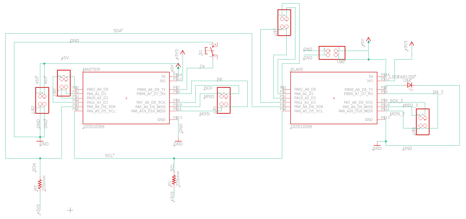
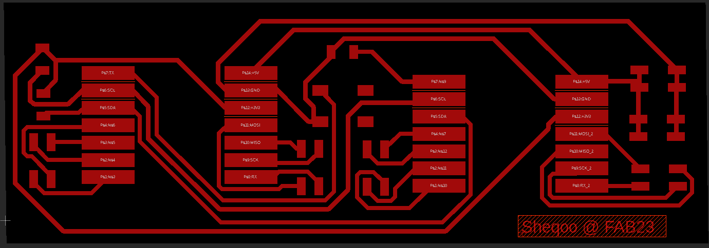
Since the two kits have the same pin out, I will use the same footprint for both boards, I will connect the Master MCU to a push button, and make a connection between the SDA and SCL of both MCU's note that I will use a PULLUP resistor to make sure that the bus line for both SDA and SCL are idling high when there is no data transmission. Also I have connected the LED on the slave with GND and an output pin.
To make benefit of all pins and to make them usable, I have connected the rest of pins to a connecters, so I could do more test using different types of protocols.
The image below, shows the schematic of the circuit on eagle, Note I will put the links of the week where I showed the process of designing on eagle at the bottom of the page.
The boards after arranging components and airing wires:
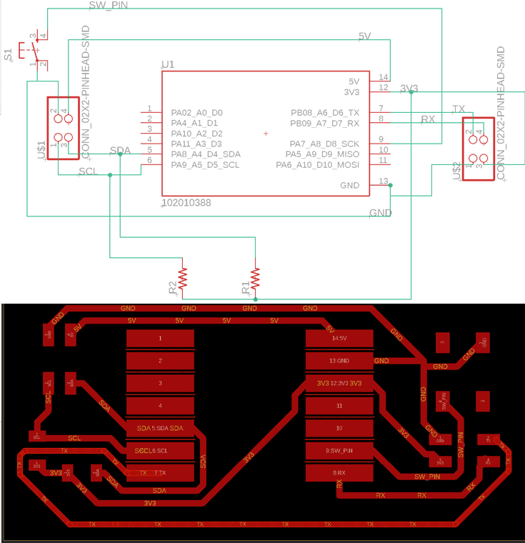
Unluckily, for this week the two boards should not be connected on the same board so I made a new schematic for each master and the slave and for sure a board.
The master schematic and board:
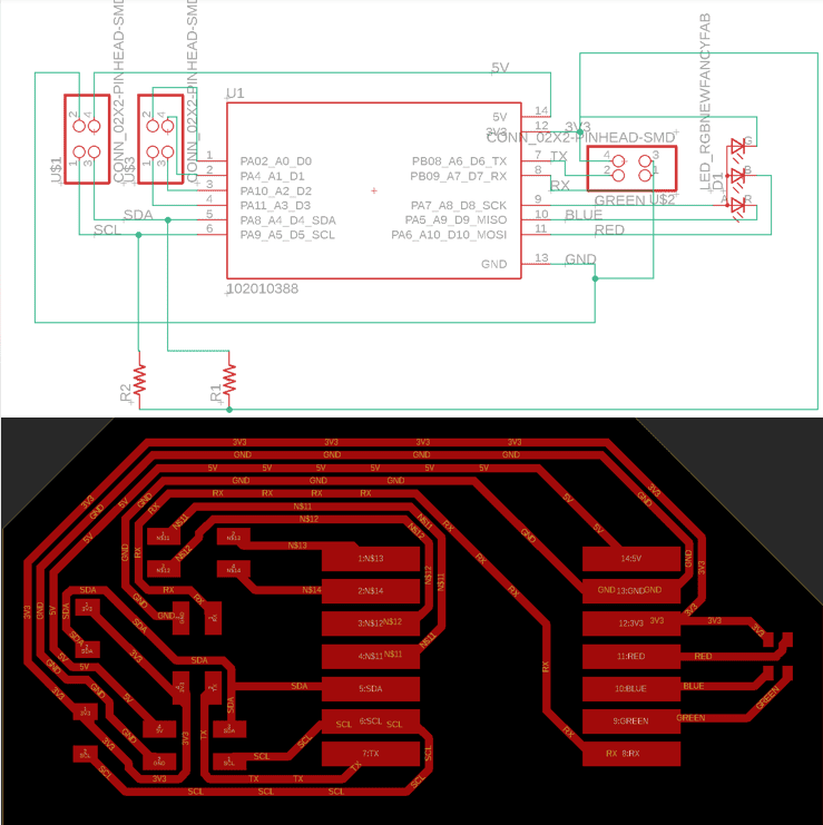
For the slave schematic and board, since it is the first time I will use the smd RGB led, I went through the datasheet of the led to know how I will connect the led based on the polarity, so I figured out the led should be connected to 3 PWM pins, each pin will control the red, green and blue light individually, and they also could be worked together to make spectrum of light, the fourth pin which is the anode should be connected to 3V pin:
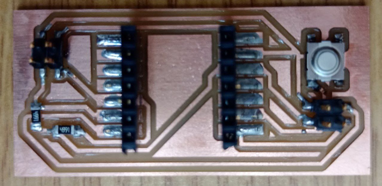
After cutting the board I have soldered the components for both boards.
Master board:
The slave board:
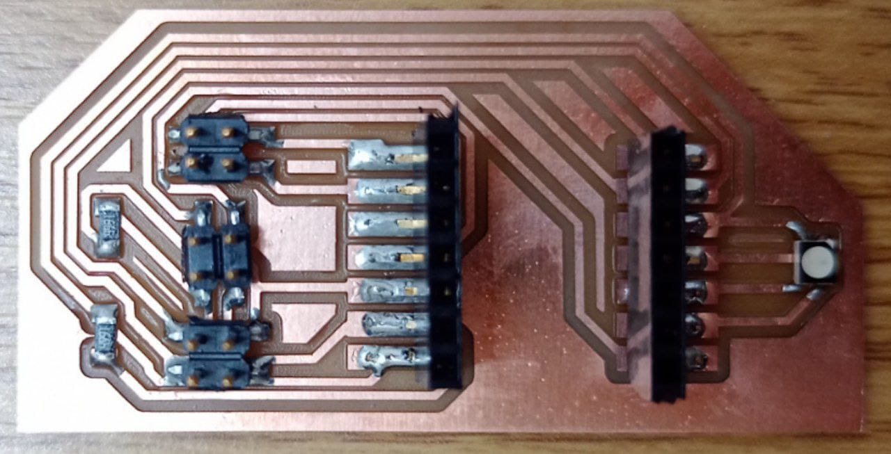
So for now, I have to program each boards. I have used a two recommended codes for the master and slave boards by our instructor Emma, and I have edited them to meet my board.
The code will be used to monitor the state of the pin 8 which is connected to the pushbutton, the default state is 1 and if the pushbutton is pressed it will wrote a zero. The Wire.begin() command is used to initialize the Wire library for I2C communication. If the switch is pressed (which means it's in a low state), the Wire.beginTransmission(5) command will tell the slave which address he have (in my case number 5), and sends him the switch state (the value is zero) using the I2C protocol, then the code will wait 0.1 second before checking and sending the signal of the pushbutton state again.
              int sw_pin = 8;
              int sw_value = 0;

              #include

              void setup()
              {
                Wire.begin(); // join i2c bus (address optional for master)
                pinMode(sw_pin, INPUT_PULLUP);
                Serial.begin(115200);
              }

              void loop()
              {

              sw_value = digitalRead(sw_pin);
              Serial.println(digitalRead(sw_pin));
              delay(100);

              if(sw_value == 0){

                Wire.beginTransmission(5); // transmit to device #5       // sends five bytes
                Wire.write(0);              // sends one byte
                Wire.endTransmission();    // stop transmitting

                delay(100);
              }

              }
I have uploaded the code to make sure the code will work properly, and it looks good:
I wanted to test the RGB alone before communication to start so I wrote the following code to test it, the code will light each color for one second by continuos loop:
              int red_pin = 10;
              int green_pin = 8;
              int blue_pin = 9;

              void setup() {
                pinMode(red_pin, OUTPUT);
                pinMode(green_pin, OUTPUT);
                pinMode(blue_pin, OUTPUT);

                Serial.begin(115200); // Initialize serial communication
              }

              void loop() {
                // Turn on the red LED for 1 second

               Serial.println("RED LIGHT ON");
                digitalWrite(red_pin, LOW);
                digitalWrite(green_pin, HIGH);
                digitalWrite(blue_pin, HIGH);

              delay(1000);

              Serial.println("BLUE LIGHT ON");
                digitalWrite(red_pin, HIGH);
                digitalWrite(green_pin, HIGH);
                digitalWrite(blue_pin, LOW);

              delay(1000);

              Serial.println("Green LIGHT ON");
                digitalWrite(red_pin, HIGH);
                digitalWrite(green_pin, LOW);
                digitalWrite(blue_pin, HIGH);

              delay(1000);

              }
When I was trying uploading the code, an error appeared "Failed uploading: uploading error: exit status 2":
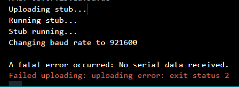
So I made some research and I found a solution credit to Rui Santos.
I will list the steps of the what I did:
1- I opened the IDE.
2- After I connected the ESP32-C3 I chose the board and port on the IDE.
3- I made long press on the reset button and the boot button on the same time, until I heard the disconnection of the USB cable.
4- I moved my hands away from the board, then I selected the port again( it disconnected because I pressed on the reset button).
5- Then on the serial monitor this message appeared, it tells that now I can reupload the code, I did it and it worked!

After uploading, the following video shows the result for testing the slave board:
Going to the slave code, I have three output pins connected to RGB LEDs to display different colors based on information received from a master device. The x variable is used to store information that is received from the master board using the I2C communication protocol. Using the Wire.begin command the communication will start, the Wire.onReceive(receiveEvent) sets the receiveEvent function to be called whenever data is received on the I2C bus. The receiveEvent function reads the received byte and stores it in the x variable, and then prints it to the serial monitor .
The program checks whether the value of x is equal to 0. If it is, then the program turns on the red LED and turns off the green and blue LEDs for 200 milliseconds, then turns on the blue LED and turns off the red and green LEDs for another 200 milliseconds, and finally turns on the green LED and turns off the red and blue LEDs for another 200 milliseconds. Then, the value of x is set to 1 and the loop starts over. If the value of x is not equal to 0, then all three LEDs are turned off.
                int red_pin = 10;
                int green_pin = 8;
                int blue_pin = 9;
                int x = 1; //variable to save the information from the master

                #include

                void setup() {

                  Wire.begin(5);                // join i2c bus with address #5
                  Wire.onReceive(receiveEvent); // register event
                  Serial.begin(115200);           // start serial for output

                  pinMode(red_pin, OUTPUT);
                  pinMode(green_pin, OUTPUT);
                  pinMode(blue_pin, OUTPUT);

                }

                void loop()
                {
                  delay(100);
                  if (x == 0){
                              // Turn on the red LED for 1 second

                              Serial.println("RED LIGHT ON");
                                digitalWrite(red_pin, LOW);
                                digitalWrite(green_pin, HIGH);
                                digitalWrite(blue_pin, HIGH);

                              delay(1000);

                              Serial.println("BLUE LIGHT ON");
                                digitalWrite(red_pin, HIGH);
                                digitalWrite(green_pin, HIGH);
                                digitalWrite(blue_pin, LOW);

                              delay(1000);

                              Serial.println("Green LIGHT ON");
                                digitalWrite(red_pin, HIGH);
                                digitalWrite(green_pin, LOW);
                                digitalWrite(blue_pin, HIGH);

                              delay(1000);


                    x=1;
                    delay(100);
                  } else {
                    digitalWrite(red_pin, HIGH);
                    digitalWrite(green_pin, HIGH);
                    digitalWrite(blue_pin, HIGH);

                  }
                }

                // function that executes whenever data is received from master
                // this function is registered as an event, see setup()
                void receiveEvent(int howMany)
                {
                  x = Wire.read();    // receive byte as an integer
                  Serial.println(x);         // print the integer
                }
For the master code, I define the switch pin number then using #include Wire.h I includes the Wire library, which is used for I2C communication. In void setup Wire.begin() initializes the I2C bus and joins it as a master device, then I sets the switch pin as an input with a pull-up resistor. In void loop the if (sw_value == 0) will checks if the switch is pressed and the Wire.beginTransmission(5) begins a transmission to a slave device with address 5 on the I2C bus. The Wire.write(0) will Send a single byte with value 0 to the slave device. Finally the Wire.endTransmission() ends the transmission to the slave device.
                    int sw_pin = 8;
                    int sw_value = 0;

                    #include

                    void setup()
                    {
                      Wire.begin(); // join i2c bus (address optional for master)
                      pinMode(sw_pin, INPUT_PULLUP);
                      Serial.begin(115200);
                    }

                    void loop()
                    {

                    sw_value = digitalRead(sw_pin);
                    Serial.println(digitalRead(sw_pin));
                    delay(100);

                    if(sw_value == 0){

                      Wire.beginTransmission(5); // transmit to device #5       // sends five bytes
                      Wire.write(0);              // sends one byte
                      Wire.endTransmission();    // stop transmitting

                      delay(100);
                    }

                    }
I made sure to connect all wires on the right pin, then I have uploaded both codes and yeah it worked!
