
Final Project, CAD
I will start designing the model using fusion 360, I will design the following parts:
1-The mold for making composite.
2-The disk where the part will set.
3-The chair where the disk will rest.
4- Flange to connect the desk and the motor rod.
5- Bracket for the motor.
6- The control panel for the electronics.
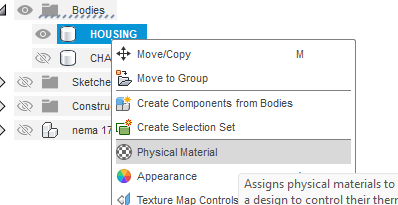
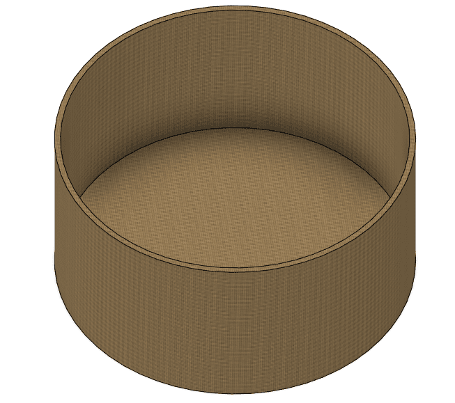
As on computer aided design week,
I drew the cylinder and I put a physical material to make it more realistic, right click on the body then physical material:
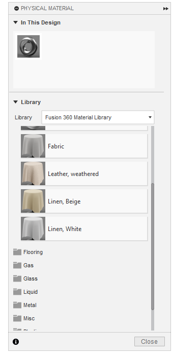
Then drag drop from the material list to the body directly:
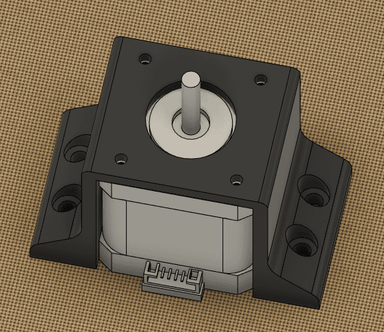
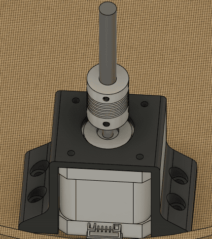
Then I imported the motor stepper motor design from a friend page then I centered it in the body, after that I drew the motor bracket to fix the motor with screws and nuts:
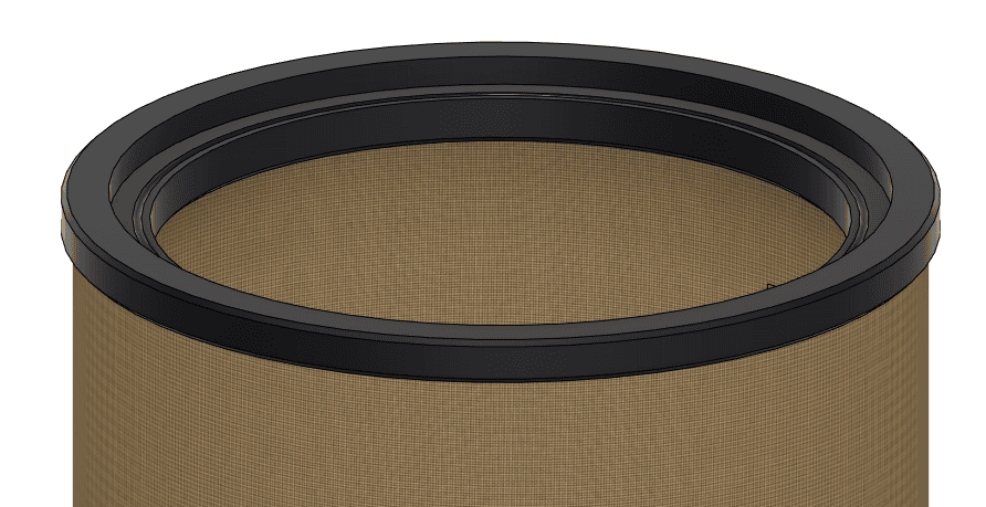
Next I drew the chair where the disk will set , I make a grove inside it (half sphere) so the bearing balls will set and rotate freely, and also I made the contour under the chair so the contour thickness will be equal to the main body wall thickness so the chair will set on the body:
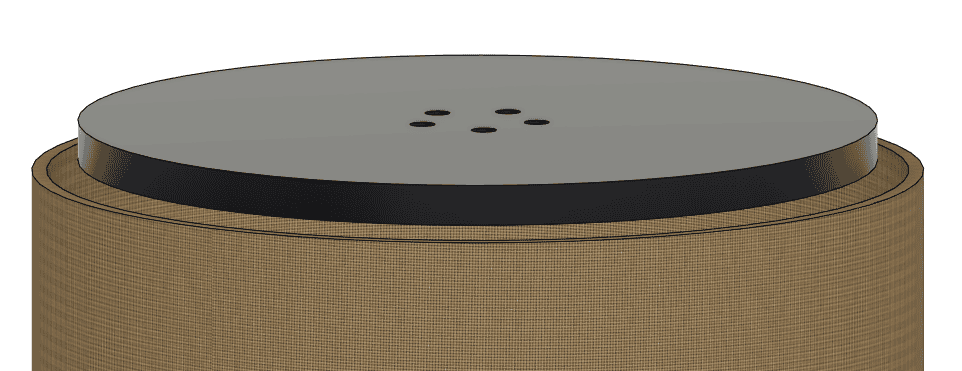
Then I drew the disk, the diameter will be smaller than the inner diameter of the chair:
After that I imported the flexible coupling, attached it to the motor shaft and the connecting rod:
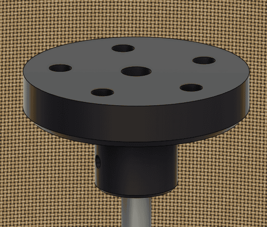
Then I drew a coupling between the connecting rod the the disk:
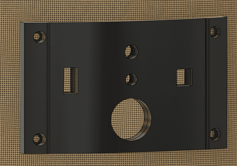
Finally I drew the control panel interface, it will be fixed using screws:
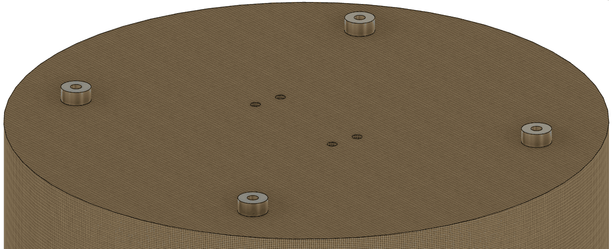
The last thing was to make a spacers under the body:
Final result: