Final Project
3D Design
to design a 3D model for the final project I used fusion 360 .
my project is basically is a 3-axis robotic arm with a soft gripper as an end effector, so to design such a project we have to make 5 essential parts ( base, rotating axis, Z-Axis, x Axis, end effector "soft gripper ").
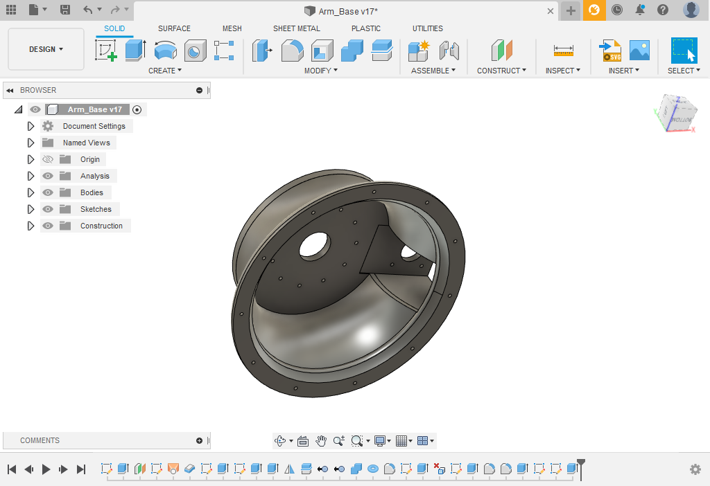
let's start with the base, here I design the base with the proper thickness ( about 5 mm) to make it stiff enough to hold out the arm weight, also I make places for screws to fix the arm in case I want to fix it afterward. and I have made a holder for the stepper motor which will move the rotating axis with M3 screws .
I have made places for M3 screws to fix the bearing holder which was in the same place before but I changed this to make two separated pecs, and because if I print this base with the bearing holder as one solid pec it will take too much time and material in the 3D printing process because of extra support in the previous model .

inside this base, you will find an empty place which is obviously for electronics integration
 fusion 360 & stl files
I choose a radial bearing with an inner diameter of 60mm, so I design the bearing holder with a 59.7 mm outer diameter that's makes the clearance 0.3mm, and it's more than enough to make the bearing fit perfectly into the holder
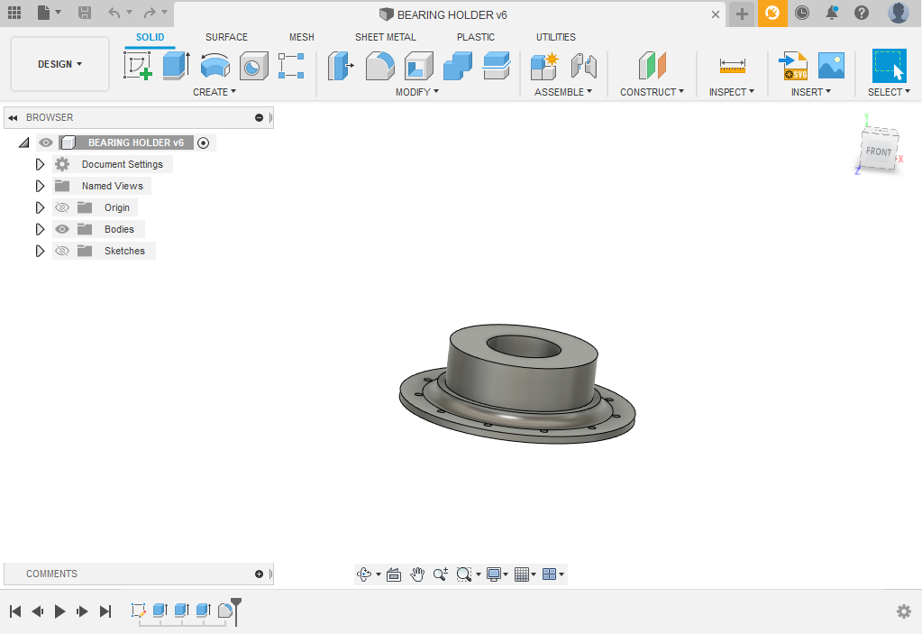
to make the CAD model realistic as much as possible I design the bearing to assemble it later .
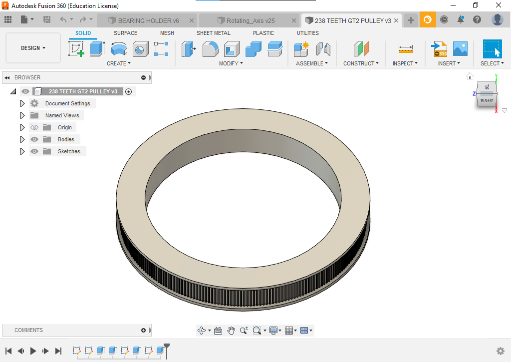
this is the rotating axis which is a contest of stepper motor and 4 linear axis road ( 8mm) to make a reel for the Z-Axis, I took into account that to move the rotating axis I will need Bulley with GT2 belt so I have made a place for the Bulley with 0.3 mm clearance .

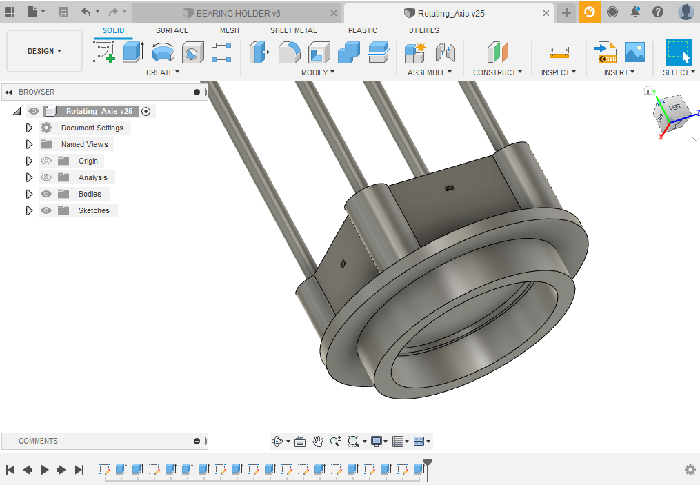
I have designed the bully from scratch to match the GT2 belt and the result was a 238 teeth bulley .
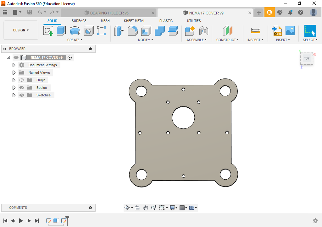
I design this part to cover and hold the stepper motor which moves the Z-Axis Up and Down. this part will be fabricated using a laser cutter because it's just 2D details there is no need to use 3D printer for this part .
this part is the x-axis holder (Z-Axis) which has the stepper motor and the nut for Z-Axis

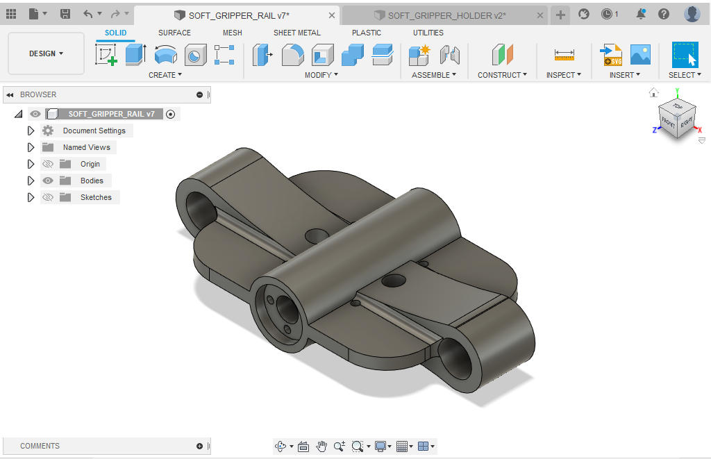
here is the end effector holder which has a sliding movement in addition to holes that designs to pass the soft gripper tubes.
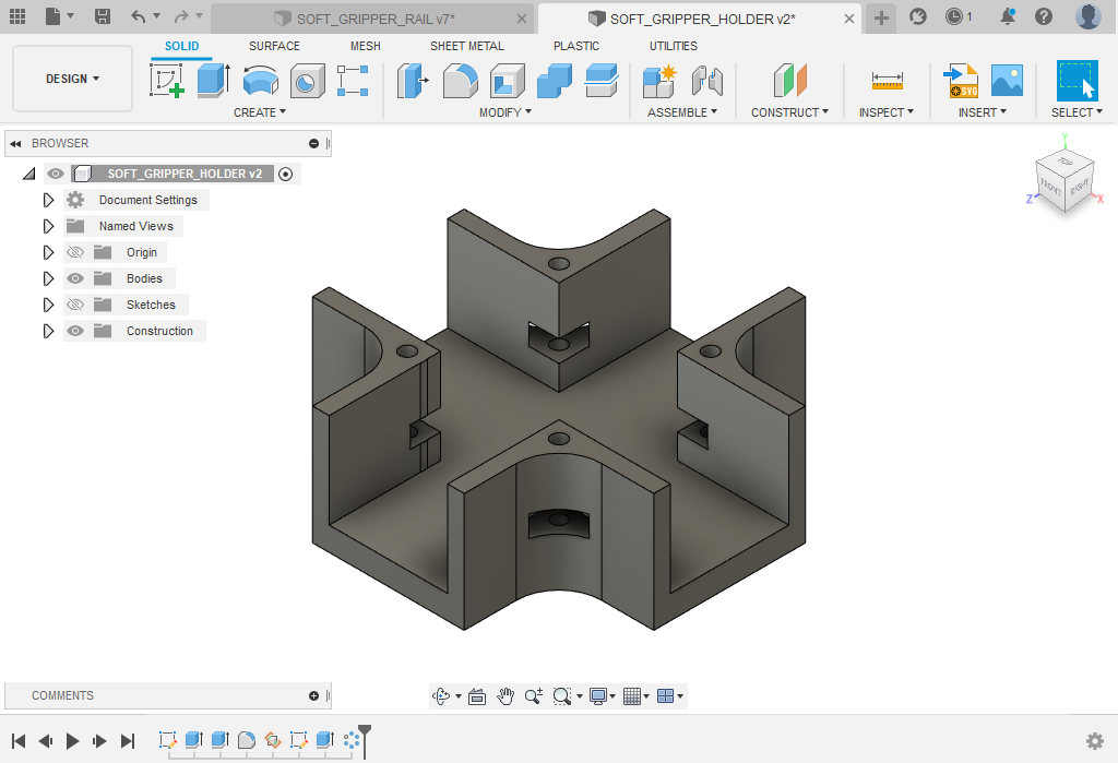
and this is the finger holder which has a place for 4 fingers and screws path to fix it with the end effector holder
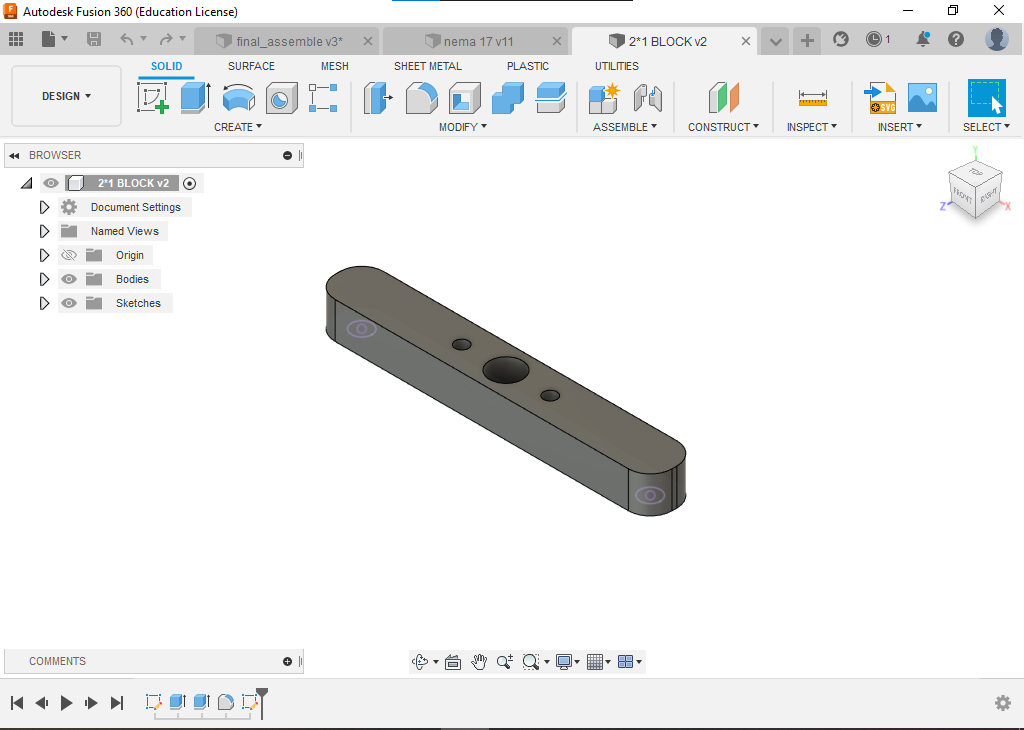
down below you will see the block part for the x-axis and Z-Axis, which will block the movement of each axis in addition to holding the block bearing .
x-axis

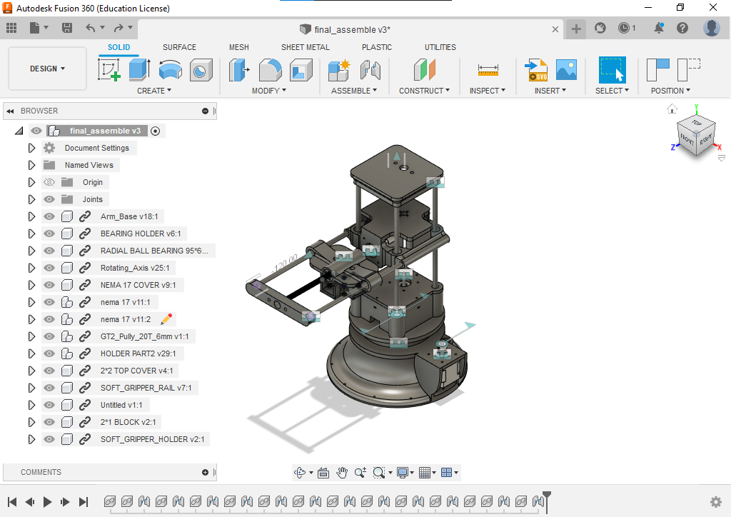
finally, this is the assembly for the design, and its ready for fabrication .