Final Project
Designing
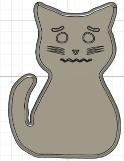
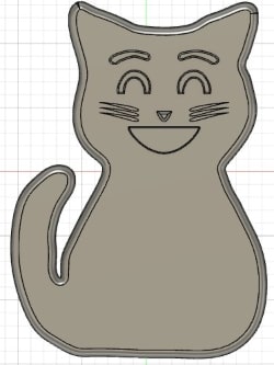
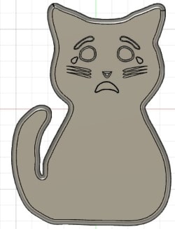
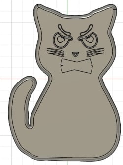
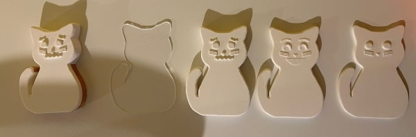
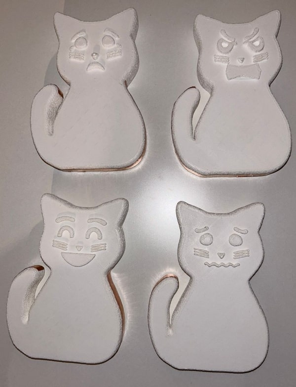
When I start designing the project, I begin with the cat that will represent my character, Bizri. I focus on the most important emotions based on the emotional wheel and my own perspective. I began designing the four cats with four different emotions. To start, I selected the four crucial emotions that children should learn to express: sadness, happiness, fear, and anger.
One of my friends assisted me in drawing a cat on blender, but it proved to be quite challenging. When I printed the initial prototype, it ended up resembling a rabbit rather than a cat. Here is the outcome.
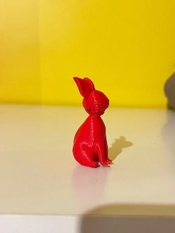
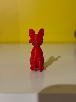
So, I made the decision to go back to something I am familiar with, which is Fusion 360.
Since I don’t possess freehand drawing skills, I utilized photos as references to trace over and achieve the desired shapes in Fusion 360. I added fillets to make the edges smoother, and I extruded the eyes, eyebrows, nose, mustache, and mouth outward from the body to enhance the tactile experience for children.

Here you can download the four cats.
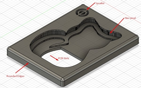
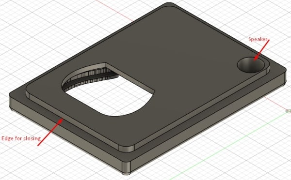
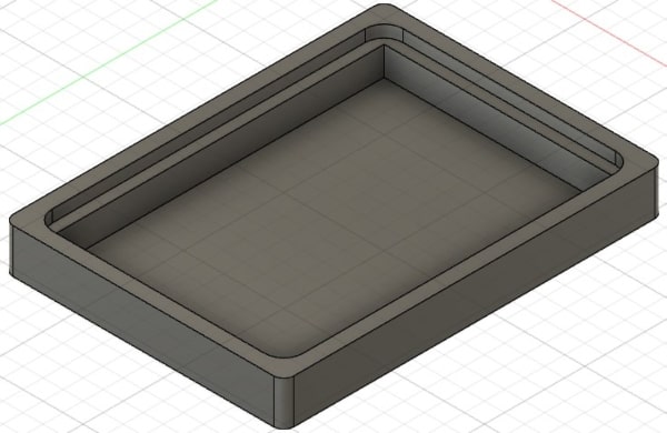
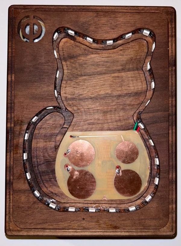
Next, I began designing the box it consists of two parts: the top part will have a pocket with the cat shape, but it will be offset by two millimeter. The thickness of this part will be 5 millimeters. After this 5 millimeters, the same cat shape will be offset by 3 millimeters, creating a surface where the child can handle the cat. On this surface, which is offset by 3 millimeters, I will create a path for the Neo Pixel light. Then I made a hole for the PCB (Printed Circuit Board) and another hole for the speaker. The microcontroller unit, DFPlayer, and power bank will be placed within the box to power the PCB. Since the PCB consists of two layers, this setup ensures proper functionality.

Here you can download the final box.
3D Printing
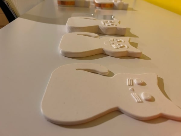
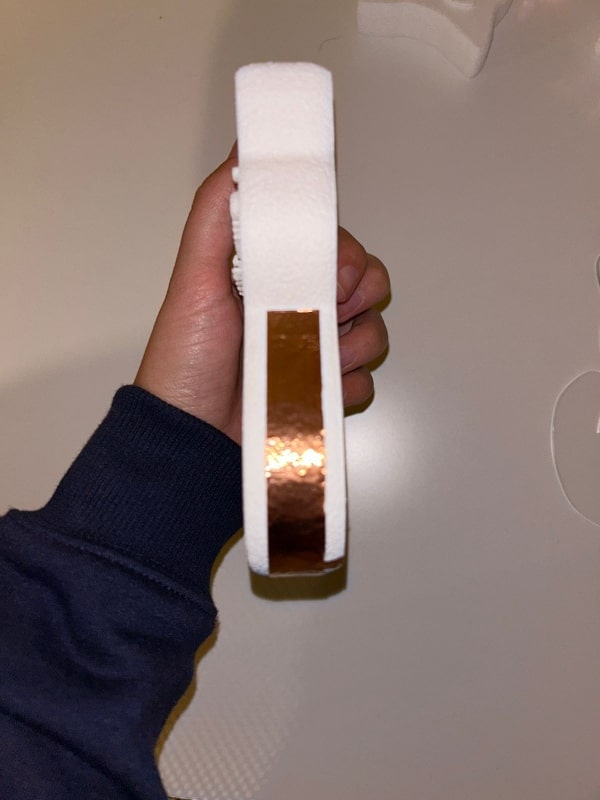
Then, I proceeded to prototype the cats using various 3D printing techniques. I initially started with an FDM (Fused Deposition Modeling) printer, specifically the Ultimaker S5. I initially used white PLA (Polylactic Acid) for the project, and the results were satisfactory. However, I wanted to test the clear resin by utilizing the SLA (Stereolithography) printer, specifically the Formlabs 3B model, also I tested one cat to cut it by laser.
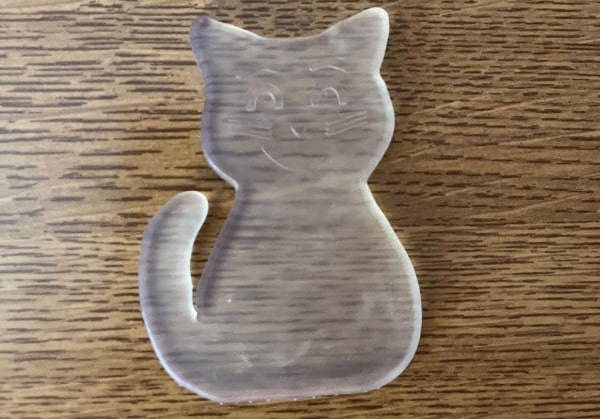
When I tested the SLA printer with clear resin material, I didn’t achieve the desired feeling for the cat model. Additionally, I realized that the PCB (Printed Circuit Board) would be visible beneath the cat. As a result, I decided to change my approach and reverted back to using FDM printing, with white PLA material.
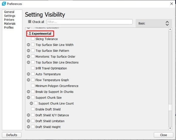
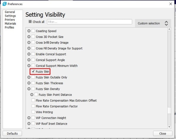
In Cura, I discovered an intriguing feature called “fuzzy skin” that provided me with a side structure resembling the hair of a cat.
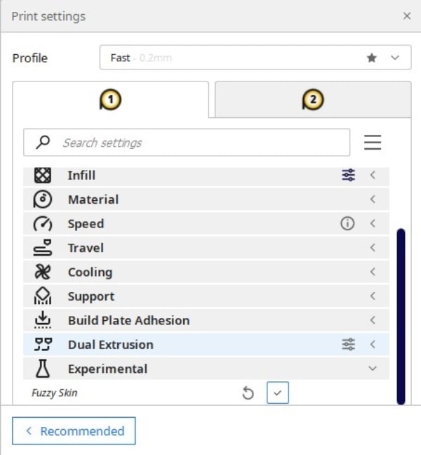
You can achieve this effect by enabling the experimental fuzzy mode.
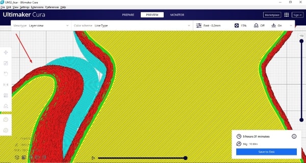
After applying the mode, navigate to the preview section to visualize the effect before proceeding with the printing.
To find the appropriate thickness that would fit the box, I experimented with different settings. Using Cura, I disabled uniform scaling and adjusted the height value in the Z section according to my desired thickness, aiming for approximately 30 mm.

CNC
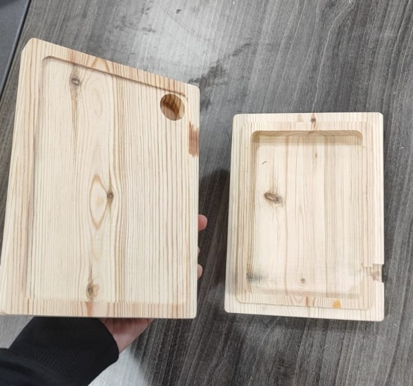
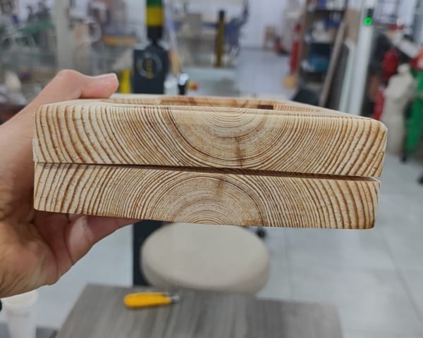
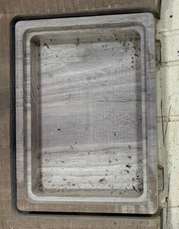
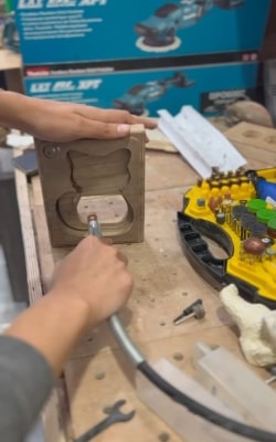
Before constructing the final box, I conducted a test using pine wood to assess the dimensions and make necessary adjustments. Some modifications I made include:
-
Creating a hole for the PCB to be mounted securely.
-
Incorporating a clearance difference of approximately 2 mm between the cover and the top to ensure proper fitting.
-
Adjusting the speaker hole to be larger to accommodate the speaker adequately.
-
Creating a pathway for the speaker wires to be neatly routed and positioned.
-
Adding a hole next to the PCB hole to allow the light wires to pass through.
By implementing these modifications, I ensured that the dimensions and features of the box were suitable for the intended components and functionality.

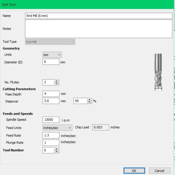
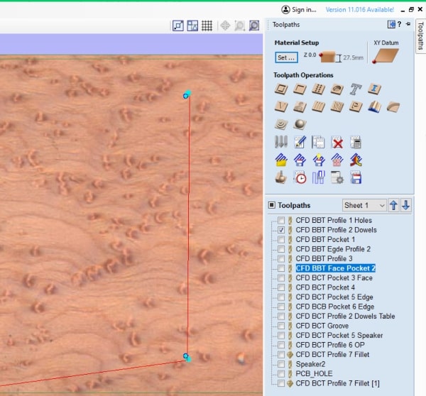
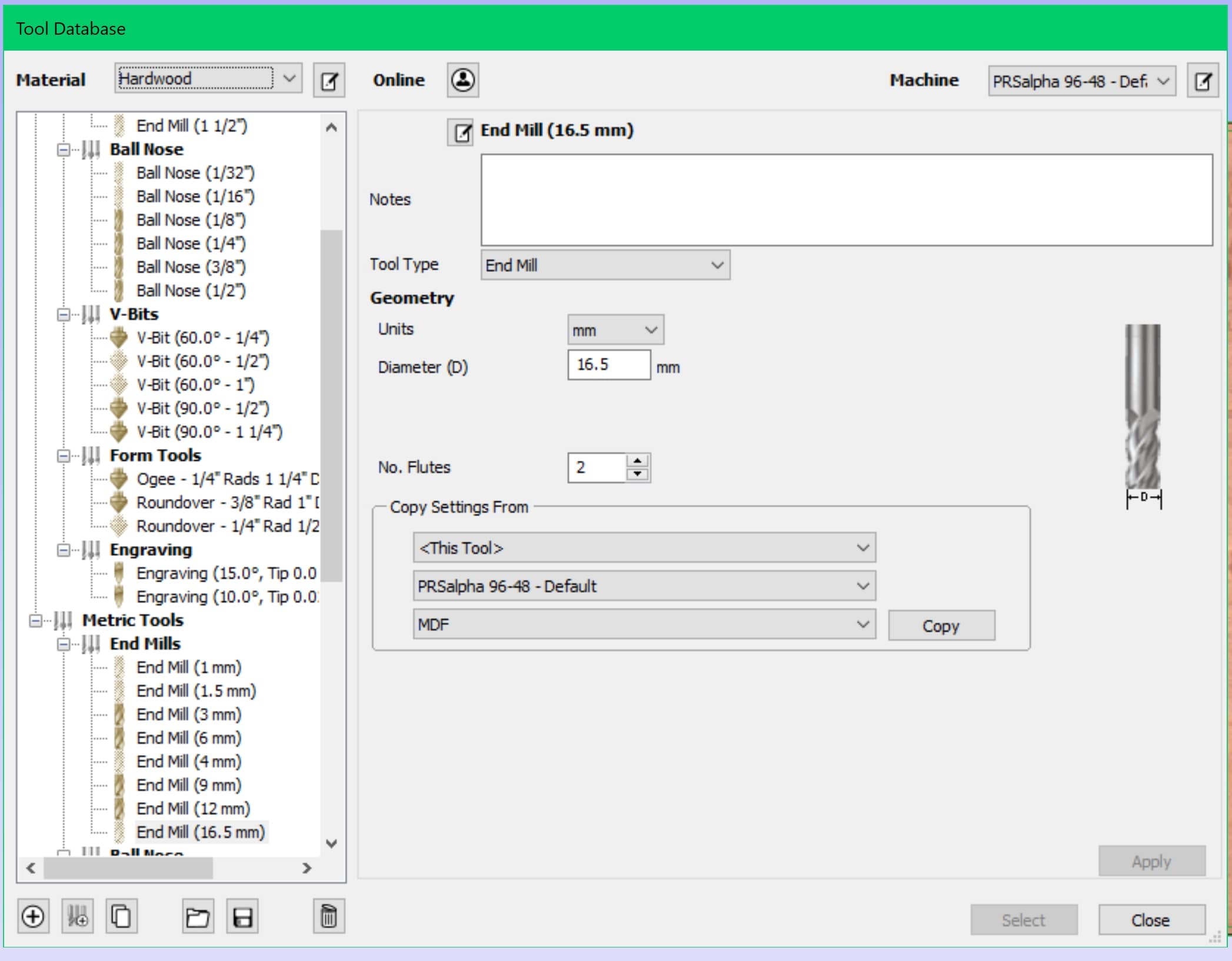
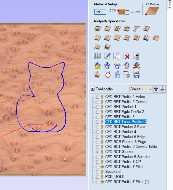
Now to create the final box, I will need to run multiple toolpaths using various tools. Let’s start with the 6-millimeter tool and visualize the paths it will follow:
The first toolpath will involve creating holes on the bed and the table. These holes serve as reference points to ensure that the workpiece can be flipped without losing its precise location. By establishing these reference points, I can confidently execute toolpaths on both sides of the workpiece.
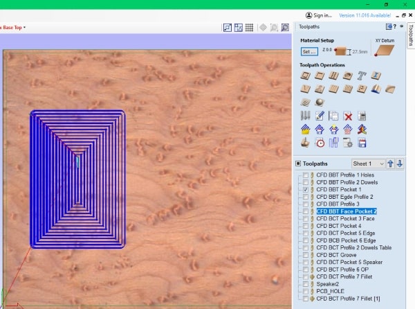
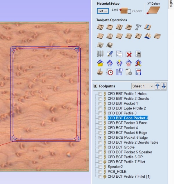
To construct the bottom part of the box, I utilized a toolpath that included a pocket and a step between the pocket and the wall. This step difference was carefully designed to ensure a secure fit between the top and bottom sections of the box. By executing the appropriate toolpaths, I achieved the desired result, allowing the top part to neatly sit atop the bottom part of the box.
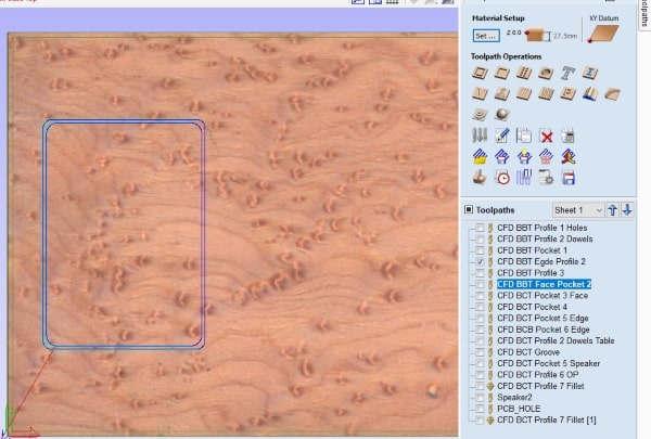
To ensure a flat surface, I executed a toolpath designed specifically for this purpose. By running this toolpath, I verified and confirmed that the surface of the workpiece is indeed flat.
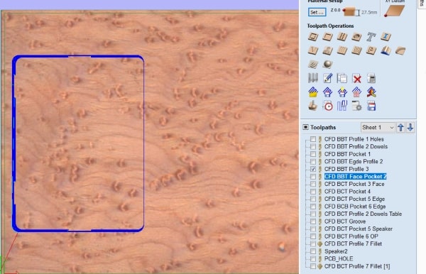
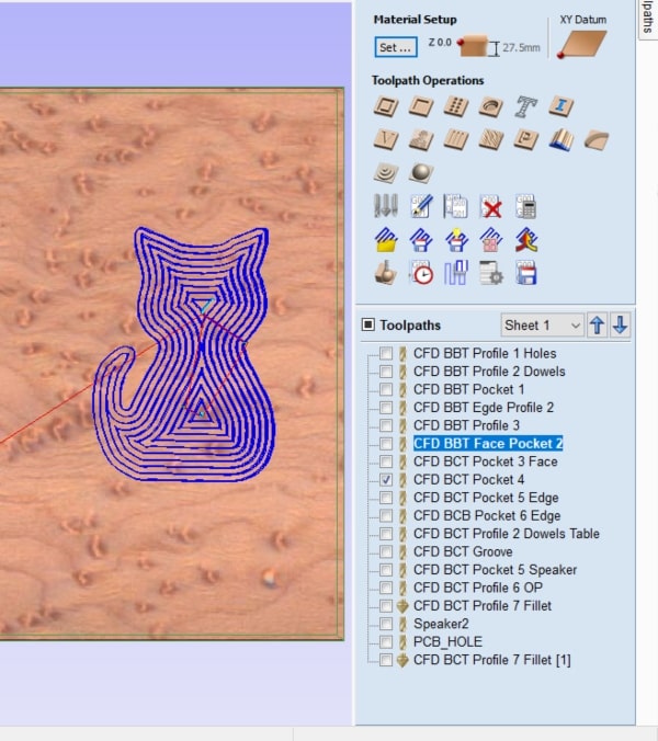
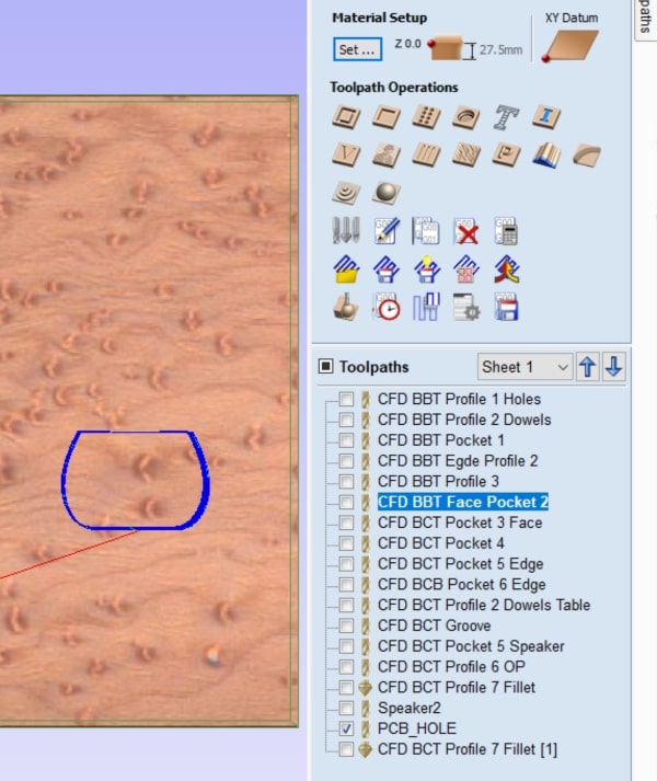
Next, I proceeded to create a pocket in the shape of the cat to accommodate the printed cats. Using appropriate toolpaths, I carefully carved out the pocket, ensuring that it matched the shape of the cats precisely. This pocket provided a designated space for the printed cats to fit snugly within the box.
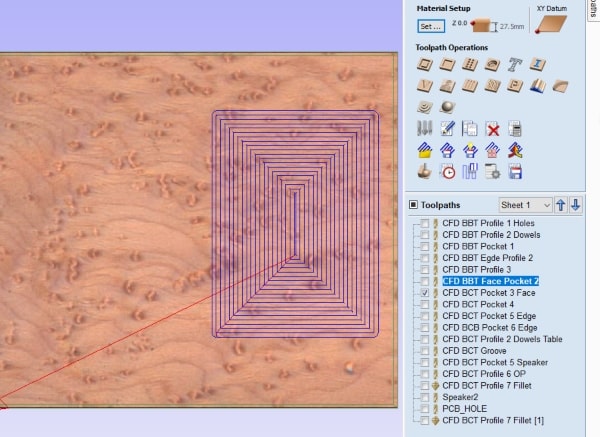
Following that, I executed two toolpaths with varying step sizes and offsets to create the desired design.
I proceeded to create the necessary hole in the box to accommodate the PCB (Printed Circuit Board). By carefully carving out the hole using the appropriate toolpaths, I ensured that the PCB would fit securely within the designated space inside the box. This hole allowed for proper placement and integration of the PCB into the overall design of the box.
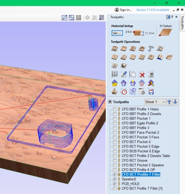
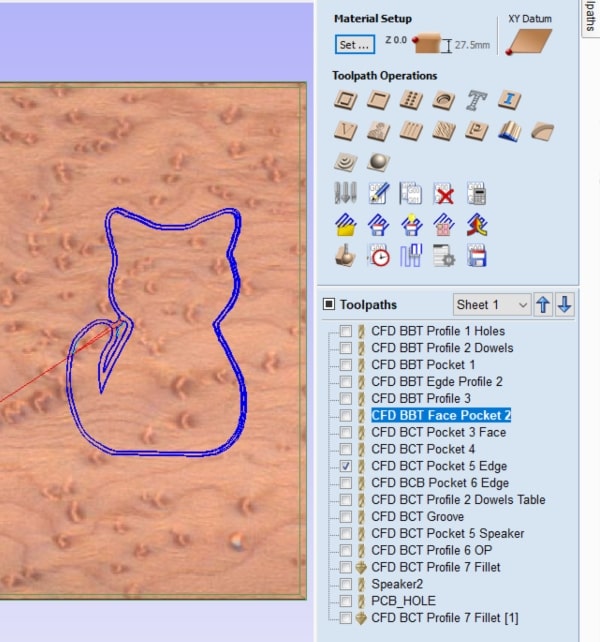
Finally, using the same tool, I executed the last toolpath, which involved cutting the top cover of the box. This toolpath was specifically designed to shape and define the contours of the top cover, giving it its final form.
Additionally, I utilized a different tool called a groove tool to create a path for the NeoPixel light to rest upon. This toolpath was specifically designed to carve out a groove or channel in the designated area where the NeoPixel light would be placed. By running this toolpath, I created a well-defined and precise path for the NeoPixel light to sit within, ensuring proper positioning and alignment.
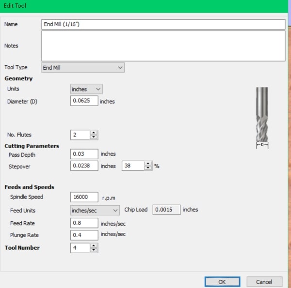
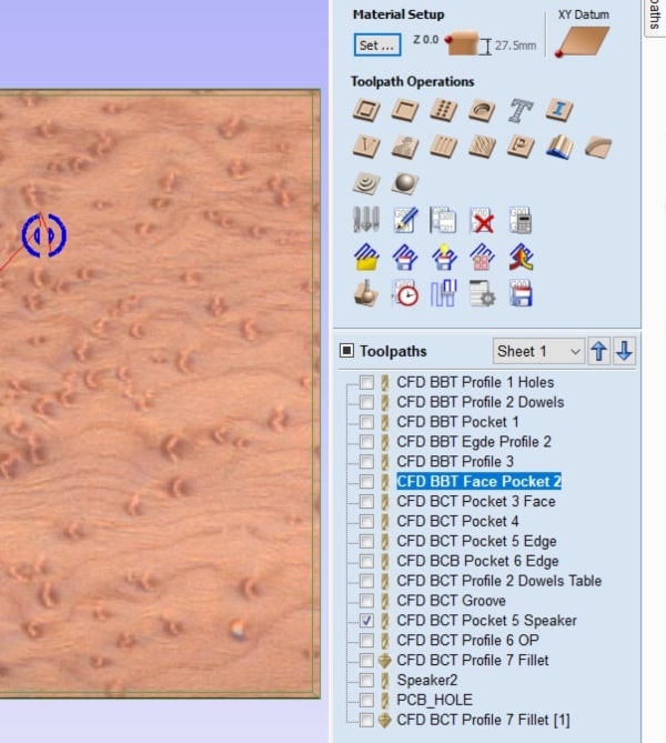
For the design of the speaker, I opted to use a 1/16 inch tool. Given the small size of the speaker design, this tool provided the necessary precision and detail required to carve out the speaker hole accurately.
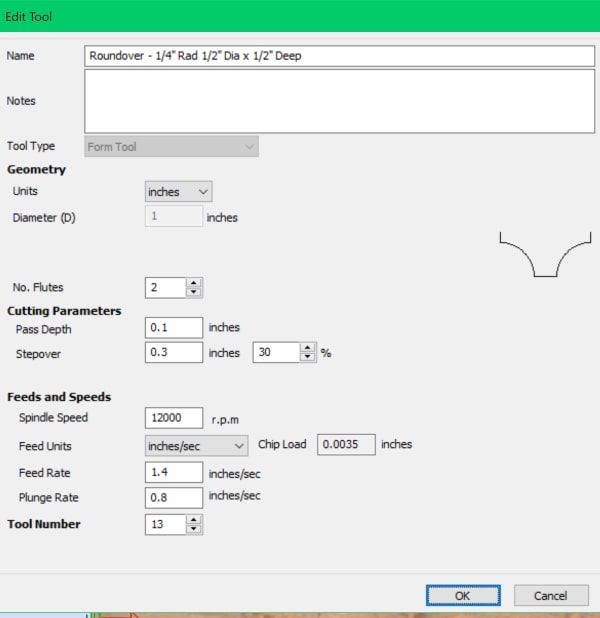
To create filleted edges, I utilized a specific tool designed for this purpose. With this tool, I applied fillets to all edges of the box, giving them a smooth and rounded appearance.
Electronics and Coding
Utilizing all the knowledge I acquired in the previous weeks, I will incorporate various components into this project. For input, I will use touch sensors, and the output will be controlled NeoPixel lights. Additionally, I will integrate a speaker into the design. To handle the microcontroller aspect, I have chosen the Seeed SAMD21, and for sound playback, I will employ the DFPlayer, which allows me to record and play sounds.
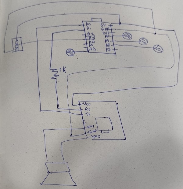
I will begin by designing the circuit on paper, ensuring that I use the correct pins and that each input and output device is connected properly. I will take the time to study and understand the specifications and requirements of each device, confirming that they are connected in the appropriate manner.
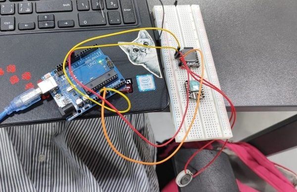
Afterwards, I proceeded to test the touch sensor with the NeoPixel light. I combined the code from the touch sensor, which I worked on during the input device week, with the NeoPixel code that I developed during the output device week. Successfully, I tested the functionality of these components using a breadboard and the touch sensor designated for the input device.
#include "Adafruit_FreeTouch.h"
#include <Adafruit_NeoPixel.h>
#ifdef __AVR__
#include <avr/power.h> // Required for 16 MHz Adafruit Trinket
#endif

#define PIN_NEO_PIXEL  A0  // Arduino pin that connects to NeoPixel
#define NUM_PIXELS     32  // The number of LEDs (pixels) on NeoPixel

Adafruit_NeoPixel NeoPixel(NUM_PIXELS, PIN_NEO_PIXEL, NEO_GRB + NEO_KHZ800);

Adafruit_FreeTouch qt_1 = Adafruit_FreeTouch(A1, OVERSAMPLE_4, RESISTOR_50K, FREQ_MODE_NONE);

void setup() {
 NeoPixel.begin(); // INITIALIZE NeoPixel strip object (REQUIRED)

 NeoPixel.clear(); // set all pixel colors to 'off'

 Serial.begin(115200);
}

int qt_Threshold = 850;


void loop() {

 int qt1 = 0;

 if (! qt_1.begin())
    Serial.println("Failed to begin qt");

   qt1 = qt_1.measure();
      Serial.println(qt1);
  if (qt1 >= qt_Threshold)
  {
  for(int i=0; i<NUM_PIXELS; i++) { // For each pixel...

  NeoPixel.setPixelColor(i, NeoPixel.Color(255, 0, 0));
  NeoPixel.show();}
  }
else {

   NeoPixel.clear();
 NeoPixel.show();

}
  }

Afterwards, I proceeded to test the speaker, although I only have a picture as evidence, not a video. The code below is for speaker you just have to put a mp3 sound on the SD card.
Here the website I followed to know more about the speaker.
SoftwareSerial mySoftwareSerial(A0, A1); // RX, TX //seeed xiao samd 21

DFRobotDFPlayerMini myDFPlayer;
void printDetail(uint8_t type, int value);

void setup()
{
 mySoftwareSerial.begin(9600);
 Serial.begin(115200);

 Serial.println();
 Serial.println(F("DFRobot DFPlayer Mini Demo"));
 Serial.println(F("Initializing DFPlayer ... (May take 3~5 seconds)"));

     if (!myDFPlayer.begin(mySoftwareSerial)) {  //Use softwareSerial to communicate with mp3.
   Serial.println(F("Unable to begin:"));
   Serial.println(F("1.Please recheck the connection!"));
   Serial.println(F("2.Please insert the SD card!"));
   while(true);
 }
 Serial.println(F("DFPlayer Mini online."));

 myDFPlayer.volume(30);  //Set volume value. From 0 to 30
myDFPlayer.play(1);  //Play the first mp3
}

void loop()
{
 static unsigned long timer = millis();

 if (millis() - timer > 3000) {
   timer = millis();
   //myDFPlayer.next();  //Play next mp3 every 3 second.
 }

 if (myDFPlayer.available()) {
   printDetail(myDFPlayer.readType(), myDFPlayer.read()); //Print the detail message from DFPlayer to handle different errors and states.
 }
}

void printDetail(uint8_t type, int value){
 switch (type) {
   case TimeOut:
     Serial.println(F("Time Out!"));
     break;
   case WrongStack:
     Serial.println(F("Stack Wrong!"));
     break;
   case DFPlayerCardInserted:
     Serial.println(F("Card Inserted!"));
     break;
   case DFPlayerCardRemoved:
     Serial.println(F("Card Removed!"));
     break;
   case DFPlayerCardOnline:
     Serial.println(F("Card Online!"));
     break;
   case DFPlayerPlayFinished:
     Serial.print(F("Number:"));
     Serial.print(value);
     Serial.println(F(" Play Finished!"));
     break;
   case DFPlayerError:
     Serial.print(F("DFPlayerError:"));
     switch (value) {
       case Busy:
         Serial.println(F("Card not found"));
         break;
       case Sleeping:
         Serial.println(F("Sleeping"));
         break;
       case SerialWrongStack:
         Serial.println(F("Get Wrong Stack"));
         break;
       case CheckSumNotMatch:
         Serial.println(F("Check Sum Not Match"));
         break;
       case FileIndexOut:
         Serial.println(F("File Index Out of Bound"));
         break;
       case FileMismatch:
         Serial.println(F("Cannot Find File"));
         break;
       case Advertise:
         Serial.println(F("In Advertise"));
         break;
       default:
         break;
     }
     break;
   default:
     break;
 }

}
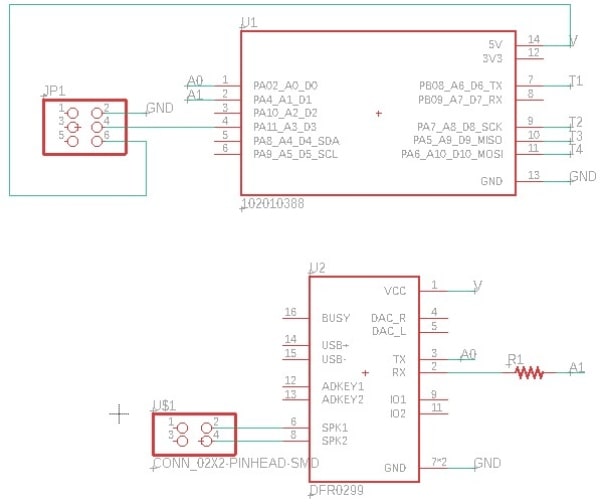
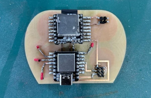
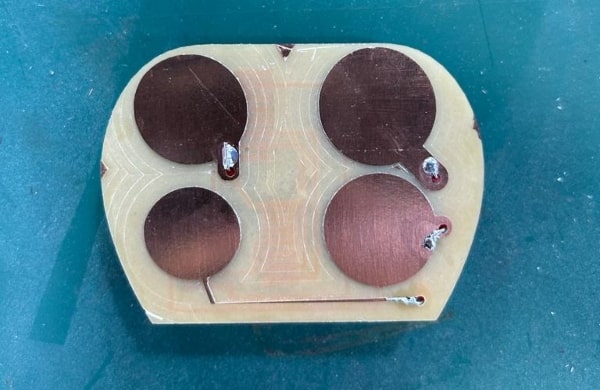
Then, I began designing the circuit using Eagle, opting for a two-layer PCB design. The first layer will include the circles for the touch sensors, while the second layer will house the microcontroller unit (MCU), DFPlayer, and the two connectors for the speaker and the light. Additionally, the PCB will have holes to facilitate interconnection between the two layers using wires.
I started with the schematic design, outlining the circuit connections and components. Following that, I proceeded to create the board layout. I utilized blue outlines to aid in correctly aligning and flipping the board; however, it didn’t prove to be very helpful in practice.
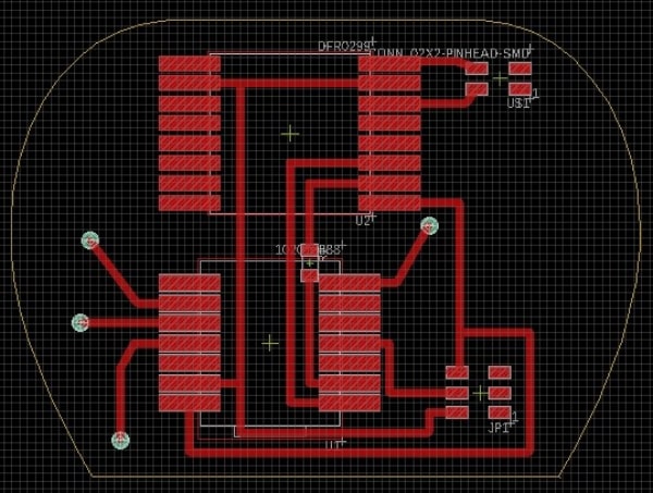
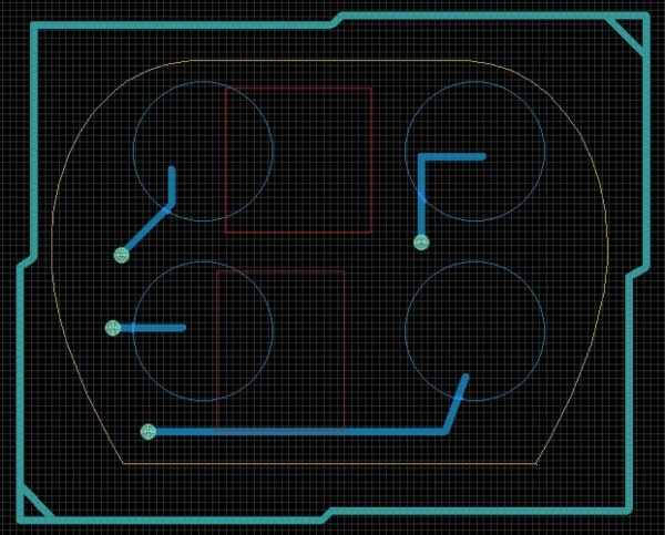
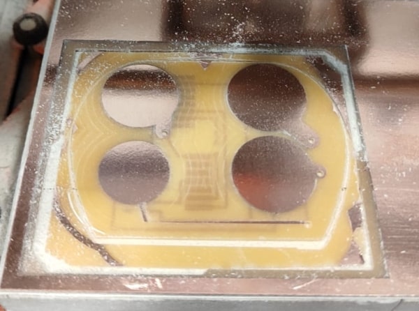
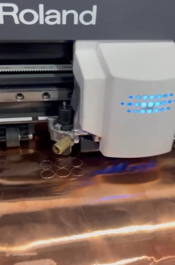
Next, I began exporting images to facilitate the modifications in the project’s workflow. To start, I focused on milling the top layer, which contained the MCU and DFPlayer. The objective was to have a clear top layer without any copper traces, ensuring that the touch sensors on the other layer would function more effectively.

To achieve a complete removal of copper on the top layer, you can set the offset number to zero (0). This ensures that all copper traces are milled away, leaving the desired clear top layer.
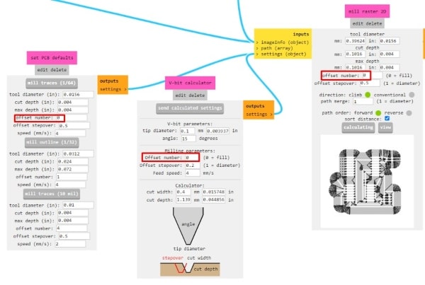
For the traces, you can use a 1/64 inch tool to achieve the desired precision. After completing the traces, you can then replace the tool with a 1/32 inch size to create the holes and the outline of the PCB.


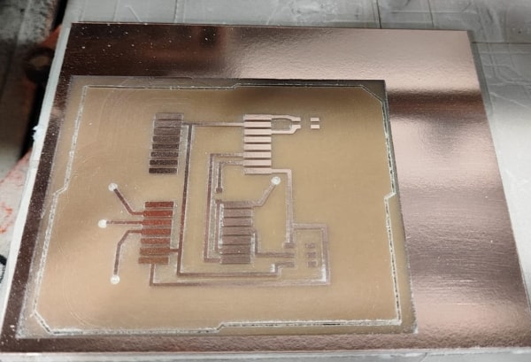
Afterward, to continue the process, you need to flip the board horizontally. This step will require you to mirror the bottom photo as well to match the flipped orientation of the board.

Afterwards, you can proceed with soldering the board. The two layers can be connected using jumper wires, allowing for the necessary electrical connections between them.
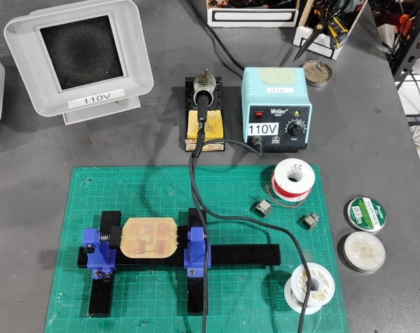
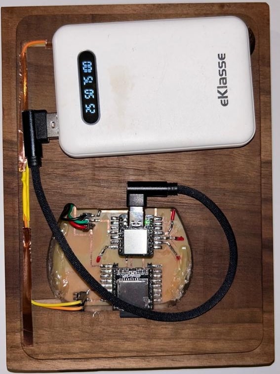
Once all the components are soldered, you can proceed to organize them within the box, placing them in their desired locations. I will use a power bank to supply power to the circuit. Additionally, I made sure to route the speaker wires along their designated path within the box for proper connectivity and placement.
#include <SoftwareSerial.h>
#include "DFRobotDFPlayerMini.h"
#include <Adafruit_NeoPixel.h>
#include "Adafruit_FreeTouch.h"

#define PIN_NEO_PIXEL  3  // Arduino pin that connects to NeoPixel
#define NUM_PIXELS     35  // The number of LEDs (pixels) on NeoPixel

Adafruit_NeoPixel NeoPixel(NUM_PIXELS, PIN_NEO_PIXEL, NEO_GRB + NEO_KHZ800);

Adafruit_FreeTouch qt_1 = Adafruit_FreeTouch(A6, OVERSAMPLE_4, RESISTOR_50K, FREQ_MODE_NONE);
Adafruit_FreeTouch qt_2 = Adafruit_FreeTouch(A8, OVERSAMPLE_4, RESISTOR_50K, FREQ_MODE_NONE);
Adafruit_FreeTouch qt_3 = Adafruit_FreeTouch(A9, OVERSAMPLE_4, RESISTOR_50K, FREQ_MODE_NONE);
Adafruit_FreeTouch qt_4 = Adafruit_FreeTouch(A10, OVERSAMPLE_4, RESISTOR_50K, FREQ_MODE_NONE);

int wait=1;

SoftwareSerial mySoftwareSerial(A0, A1); // RX, TX //seeed xiao samd 21

DFRobotDFPlayerMini myDFPlayer;
void printDetail(uint8_t type, int value);

void setup()
{
 mySoftwareSerial.begin(9600);
 Serial.begin(115200);

 Serial.println();
 Serial.println(F("DFRobot DFPlayer Mini Demo"));
 Serial.println(F("Initializing DFPlayer ... (May take 3~5 seconds)"));

     if (!myDFPlayer.begin(mySoftwareSerial)) {  //Use softwareSerial to communicate with mp3.
   Serial.println(F("Unable to begin:"));
   Serial.println(F("1.Please recheck the connection!"));
   Serial.println(F("2.Please insert the SD card!"));
   while(true);
 }
  NeoPixel.begin(); // INITIALIZE NeoPixel strip object (REQUIRED)

NeoPixel.clear(); // set all pixel colors to 'off'


 Serial.println(F("DFPlayer Mini online."));

 myDFPlayer.volume(30);  //Set volume value. From 0 to 30
//= myDFPlayer.play(1);  //Play the first mp3
}

int qt_Threshold = 850;


void loop()
{
/* static unsigned long timer = millis();

 if (millis() - timer > 3000) {
   timer = millis();
   //myDFPlayer.next();  //Play next mp3 every 3 second.
 }
*/

 int qt1 = 0;
 int qt2 = 0;
 int qt3 = 0;
 int qt4 = 0;

 if (! qt_1.begin())
   Serial.println("Failed to begin qt");
 if (! qt_2.begin())
   Serial.println("Failed to begin qt");
 if (! qt_3.begin())
   Serial.println("Failed to begin qt");
 if (! qt_4.begin())
   Serial.println("Failed to begin qt");


    qt1 = qt_1.measure(); //ANGER

  if (qt1 >= qt_Threshold) {
NeoPixel.clear();

  for(uint16_t i=0; i<NUM_PIXELS; i++) {
 NeoPixel.setPixelColor(i, NeoPixel.Color(128, 0, 128));
   NeoPixel.show();
   delay(wait);
 }
 myDFPlayer.play(1);
   delay(2000);

}

    qt2 = qt_2.measure(); //SAD

  if (qt2 >= qt_Threshold) {
NeoPixel.clear();

  for(uint16_t i=0; i<NUM_PIXELS; i++) {
 NeoPixel.setPixelColor(i, NeoPixel.Color(250, 250, 0));
   NeoPixel.show();
   delay(wait);
 }
 myDFPlayer.play(2);
   delay(2000);

}

qt3 = qt_3.measure(); //HAPPY

  if (qt3 >= qt_Threshold) {
NeoPixel.clear();

  for(uint16_t i=0; i<NUM_PIXELS; i++) {
 NeoPixel.setPixelColor(i, NeoPixel.Color(0, 0, 139));
   NeoPixel.show();
   delay(wait);
 }
 myDFPlayer.play(3);
   delay(2000);

}

qt4 = qt_4.measure(); //HAPPY


  if (qt4 >= qt_Threshold) {
NeoPixel.clear();

  for(uint16_t i=0; i<NUM_PIXELS; i++) {
 NeoPixel.setPixelColor(i, NeoPixel.Color(250, 0, 0));
   NeoPixel.show();
   delay(wait);
 }
 myDFPlayer.play(4);
   delay(2000);

}

}
The code explanation is as follows:
The project consists of four touch sensors, each corresponding to one of the four cats. The cats are designed in a way that they have copper in specific areas that will make contact with the copper traces on the circuit. When a particular cat is touched, a specific code segment associated with that cat will be executed.
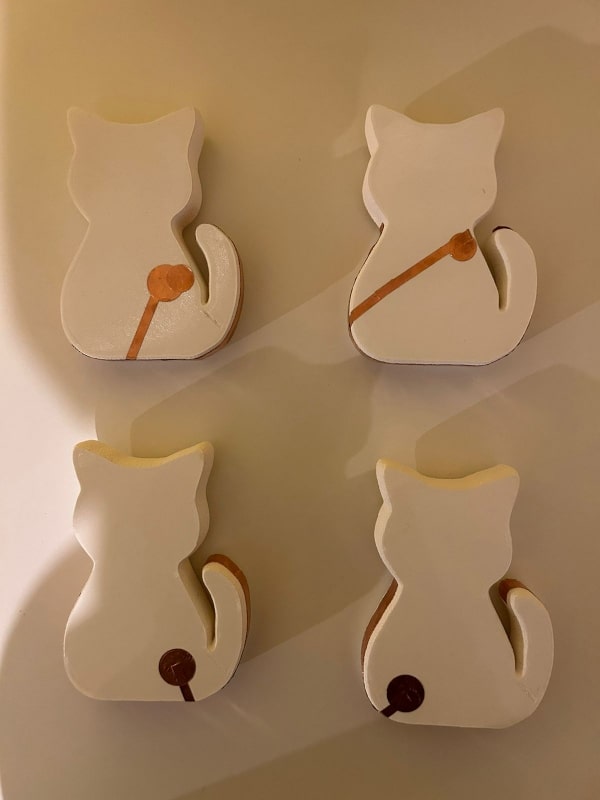
To achieve this functionality, the code uses conditional statements (if statements). Each if statement checks if the corresponding touch sensor is activated. For example, when the first touch sensor is triggered, the code within the first if statement will run. The code within each if statement can include actions like controlling the NeoPixel lights, playing specific sounds through the speaker, or any other desired behavior specific to the corresponding cat.
By detecting which touch sensor is activated through the copper connections, the code determines which cat has been touched and performs the desired actions accordingly.
Here you can download the PCB.
Finishing and Assembling
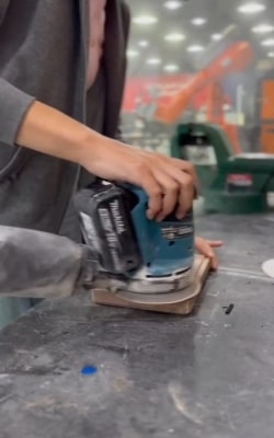
During the finishing process, I undertook two steps to achieve a smoother surface: the first one is sanding the box.
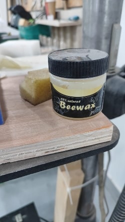
After sanding the box to achieve a smoother surface, the next step in the finishing process involved using wax. I applied wax to fill any gaps on the wood and provide a shiny surface.
After completing the aforementioned steps, I proceeded to place everything in their respective locations. The result was a fully assembled piece, showcasing the integration of all the components.

Final Result

Here is the final result.