Embedded Programming
Hello! On the embedded programming week, I will be starting to study basic command lines by running some sketches. I will discuss the new things that I learn.
Before we start, let’s begin by comparing the performance and development workflows for different microcontrollers.
Installing boards in Arduino
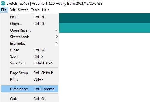
Okay, when we need to work with different boards using Arduino, we need to install the boards. You can follow these steps, in my situation, I will download the Seeed Studio XIAO RP2040. 1. In your Arduino IDE, go to File, Preferences.
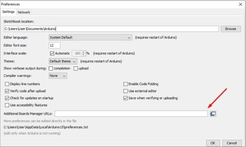
- Now you need to search for the Additional Board Manager URLs and paste it here. Here is the link where I obtained the URL from.
The URL for Seeed XIAO RP2040 is: https://github.com/earlephilhower/arduino-pico/releases/download/global/package_rp2040_index.json
- Go to the “Tools” menu, and select “Board” and then “Boards Manager”
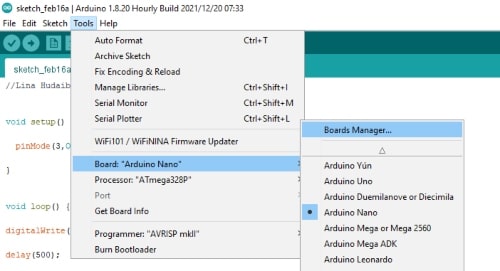
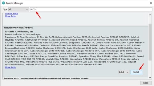
- In the “Boards Manager” window, you can search for the board you want to install by typing its name in the search box. Once you find the board, click on it and then click the “Install” button.
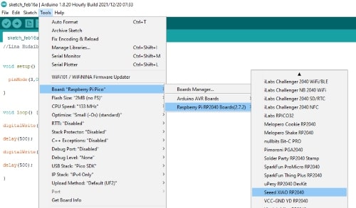
- Go to the “Tools” menu, select “Board”, and then select the board you just installed.
Performance for different microcontrollers
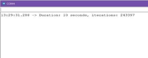
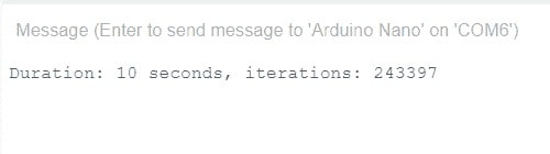
The task assigned to the group was to evaluate the performance of various modules and compare the number of iterations within the same time period. So, here we go.
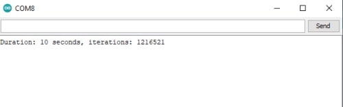
I will run the code below and check the serial monitor to observe the output.
The code:
#include "Arduino.h"

unsigned long timeNow, it = 0;
unsigned long timeLast = 0;
boolean running = true;

void setup() {
    Serial.begin(115200);
    timeNow = millis() / 1000;
    timeLast = timeNow;
}

void loop() {
    if (!running)
        return;
// Time Range of exact 10 seconds
    if (timeLast + 10 > timeNow) {
        it = it + 1;
    } else {
        Serial.print("Duration: ");
        Serial.print(timeNow);
        Serial.print(" seconds, iterations: ");
        Serial.println(it);
        running = false;
    }
    timeNow = millis() / 1000;
}
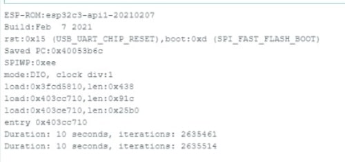
The result:
The best microcontroller performance is the one that can make the highest number of iterations in 10 seconds.
- ESP WROOM 32:
- Xiao ESP3 3C:
- Arduino UNO:
- Arduino NANO:
- XIO-RP-2040:
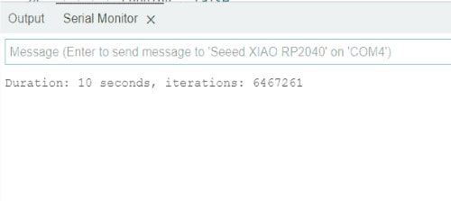
The XIAO-RP-2040 was the fastest among them and with the best performance.
The XIAO-RP-2040
The Seeed Studio XIAO RP2040 is a compact microcontroller board that is compatible with the Raspberry Pi RP2040 ecosystem. It shares the same RP2040 chip and supports multiple programming languages such as C, MicroPython, and CircuitPython.
Key features of the XIAO RP2040 include:
Powerful MCU: It features a dual-core ARM Cortex-M0+ processor with a flexible clock running up to 133 MHz.
On-Chip Resources: The board offers 264KB of SRAM and 2MB of on-board Flash memory, providing ample resources for your projects.
Flexible Compatibility: It supports MicroPython, Arduino, and CircuitPython, giving you flexibility in choosing your preferred programming language.
Small Size: With dimensions as small as 20x17.5mm, it is compact and suitable for wearable devices and small projects.
Multiple Interfaces: The board offers 11 digital pins, 4 analog pins (3 of which are usable), 11 PWM pins, and interfaces for I2C, UART, SPI, and SWD bonding pad.
Regarding power supply, it operates at 3.3V for general I/O pins. Applying voltage higher than 3.3V to these pins may cause damage. However, the built-in DC-DC converter circuit can convert 5V to 3.3V, allowing you to power the device using a 5V supply through VIN-PIN and 5V-PIN.
For more detailed information and the pinout sheet, you can refer to the Seeed Studio XIAO RP2040 documentation available on the Seeed Studio website or in the data sheet.
Basics of programming
I received all the codes and circuits from my instructor Emma’s slides, and I plan to make modifications to each one.
RP2040_Led
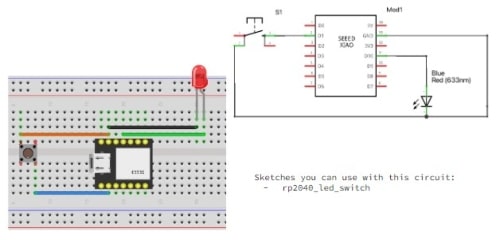
The circuit for the four coming codes:
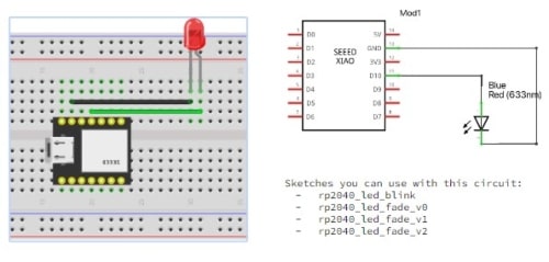
RP2040_Led_Blink
The code:
int led_pin = 3;


void setup() {

  pinMode(led_pin, OUTPUT);

}

void loop() {

  digitalWrite(led_pin, HIGH);

  delay(5000);

  digitalWrite(led_pin, LOW);

  delay(500);

}
The result:
I will study and modify the delay command, which provides a timed pause within a script. It specifies the duration of a pause in milliseconds. When you enter “delay 1000” in your script, it delays the start of the execution of the next command for approximately one second.
RP2040_Led_Fade_v0
The code:
int Zabour = 3;

void setup() {

 PinMode(Zabour, OUTPUT);

}

void loop() {

 analogWrite(Zabour, 0);

 delay(500);

 analogWrite(Zabour, 64);

 delay(500);

 analogWrite(Zabour, 128);

 delay(500);

 analogWrite(Zabour, 192 );

 delay(500);

 analogWrite(Zabour, 255);

 delay(1000);

 analogWrite(Zabour, 192 );

 delay(500);

 analogWrite(Zabour, 128);

 delay(500);

 analogWrite(Zabour, 64);

 delay(500);

 analogWrite(Zabour, 0);

 delay(500);

}
The result:
To discuss how to declare an integer variable called Zabour using the int command, we would write: “int Zabour = 3” . The “int” keyword comes first, followed by the name of the variable. Then, we set the variable equal to a number, variable, or function. This makes it easier for us to reference the variable later in our code.
The command analogWrite() takes two parameters: the first specifies the pin, and the second is a value between 0 and 255. Because the pins provide 5 volts, the equation for determining the output voltage is (value/255 * 5V).
I changed the variable name and analog write value in this code and observed the difference in changing the value by the light intensity.
RP2040_Led_Fade_v1
The code:
int led_pin = 3;

void setup() {

pinMode(led_pin, OUTPUT);

}

void loop() {

  for (int i = 255; i >= 0; i--) {
    analogWrite(led_pin, i);
    delay(10);
  }
}
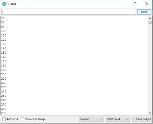
The result:
for (initialization; condition; increment) {
  // statement(s);
}
The syntax for a “for” loop includes three parameters: initialization, condition, and increment. Initialization is performed once at the beginning of the loop. Condition is tested before each iteration of the loop, and if it evaluates to true, the statements within the loop’s block are executed, followed by the increment. This process repeats until the condition becomes false, at which point the loop terminates.
On this code, I modified the code to light up at maximum intensity first and then gradually dim until it turns off, instead of going from turning off mode to lighting up by changing the for loop from this:
for (int i = 255; i <= 0; i++)
To this:
for (int i = 255; i >= 0; i--)
RP2040_Led_Fade_v2
The code:
int led = 3;
int brightness = 0;
int fadeAmount = 10;


void setup() {

  Serial.begin(9600);
  pinMode(led, OUTPUT);
}


void loop() {

  analogWrite(led, brightness);

  Serial.println(brightness);

  brightness = brightness + fadeAmount;


  if (brightness <= 0 || brightness >= 255) {
    fadeAmount = -fadeAmount;

  }


  delay(30);
}
In Arduino, the double vertical bars || are used as the logical OR operator. It is used to check if at least one of two conditions is true. The code will increment the fadeAmount until it reaches the maximum intensity of 255, and when the condition is met, it will begin decrementing the fadeAmount until it reaches zero. Once it does, the condition will become true again, and the cycle will continue.
I modified this code by changing the fadeAmount, which will result in more steps when turning towards the maximum and minimum.
The result:
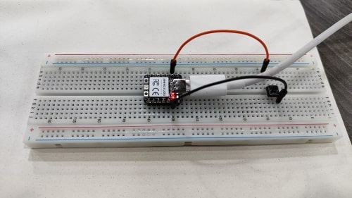
RP2040_Switch
The circuit:
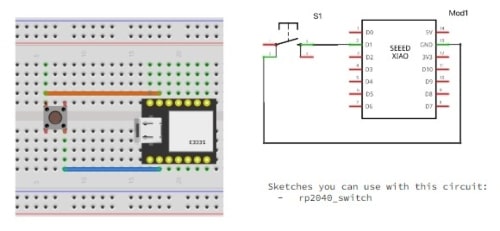
The code:
int digital_sensor_pin = 27;

int digital_sensor_value = 0;


void setup() {

  pinMode(digital_sensor_pin, INPUT_PULLUP);


  Serial.begin(9600);

}

void loop() {

  digital_sensor_value = digitalRead(digital_sensor_pin);

  Serial.print("Zero or One: ");

  Serial.println(digital_sensor_value);

  delay(100);

}
The result:
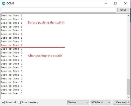
I will use this code as an opportunity to study and familiarize myself with the “serial.begin” command.
The “serial.begin” command is the most commonly used command for serial communication.
We use it when we want to print something from the microcontroller to the computer via a USB cable.
This command is usually placed in the “void setup” function because we need to establish it once in the code. It’s important to make sure that the serial number in the code matches the number on the serial monitor window.
Lastly, I’d like to mention that 9600 is the baud rate, which refers to the number of bits per second.
RP2040_Led_Switch
The circuit:
The code:
int digital_sensor_pin = 27;
int digital_sensor_value = 0;
int led_pin = 3;


void setup() {

  pinMode(digital_sensor_pin, INPUT_PULLUP);
  pinMode(led_pin, OUTPUT);
  Serial.begin(9600);

}

void loop() {
  digital_sensor_value = digitalRead(digital_sensor_pin);


  if(digital_sensor_value == HIGH){

      digitalWrite(led_pin, HIGH);
      Serial.println("the Led is ON.");

  } else {

      digitalWrite(led_pin, LOW);

  }

}
The result:
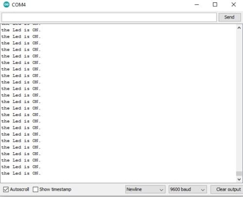
We should make it clear that pressing the switch and turning the light on are not directly related, as the code is what controls this function.
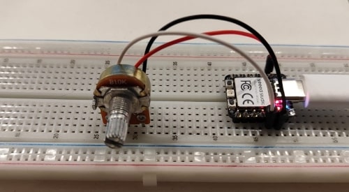
RP2040_Pot
The circuit:
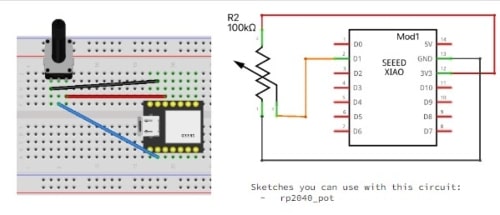
The code:
int pot_sensor_pin = 27;
int pot_sensor_value = 0;
void setup() {
pinMode(pot_sensor_pin, INPUT);
Serial.begin(9600);
}
void loop() {
pot_sensor_value = analogRead(pot_sensor_pin);
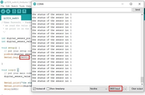
Serial.print("the status of the sensor is: ");
Serial.println(pot_sensor_value);
delay(100);
}
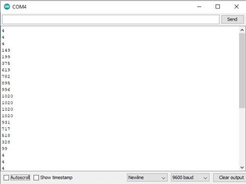
The result:
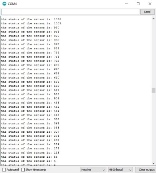
“analogRead” is a function that will read analog voltage not low and high but the values between them the “analogRead” function takes an analog pin number as input and returns a digital value ranging from 0 to 1023, This range is based on a binary system with a capacity of 2 to the power of 10.
The maximum value that “analogRead” function can return is 1023, which corresponds to 5 volts, when the analog voltage is at its minimum level of 0 volts, “analogRead” function returns 0.
RP2040_Pot_Led
The circuit:
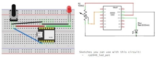
The code:
int ledPin = 3;
int sensorpin = 27;
int sensorvalue = 0;


void setup() {

  pinMode(ledPin, OUTPUT);
  pinMode(sensorPin, INPUT);

  Serial.begin(9600);

}

void loop() {

  sensorValue = analogRead(sensorPin);

  analogWrite(ledPin, sensorValue);

  Serial.println(sensorValue);


delay(500);

}
The result:
After we become familiar, I will control a LED using a potentiometer so that we can smoothly reach the maximum and minimum values.
WI-FI_Scan
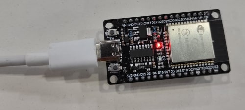
I switched to using the ESP WROOM 32 211-161007 as my development microcontroller.
From here, I took the code and ran it on my MCU
The circuit:
The code:
#include "WiFi.h"

void setup()
{
    Serial.begin(115200);

    WiFi.mode(WIFI_STA);
    WiFi.disconnect();
    delay(100);

    Serial.println("Setup done");
}

void loop()
{
    Serial.println("scan start");

    // WiFi.scanNetworks will return the number of networks found
    int n = WiFi.scanNetworks();
    Serial.println("scan done");
    if (n == 0) {
        Serial.println("no networks found");
    } else {
        Serial.print(n);
        Serial.println(" networks found");
        for (int i = 0; i < n; ++i) {
            // Print SSID and RSSI for each network found
            Serial.print(i + 1);
            Serial.print(": ");
            Serial.print(WiFi.SSID(i));
            Serial.print(" (");
            Serial.print(WiFi.RSSI(i));
            Serial.print(")");
            Serial.println((WiFi.encryptionType(i) == WIFI_AUTH_OPEN)?" ":"*");
            delay(10);
        }
    }
    Serial.println("");


    delay(5000);
}
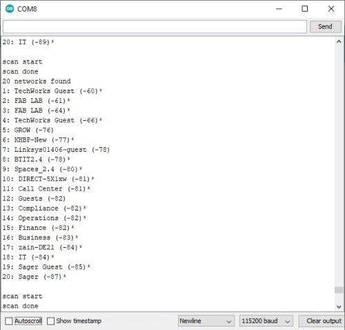
The result:
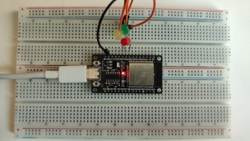
ESP32 Web Server – Arduino IDE
After copying the code from here , I made some modifications by including an additional button and LED that can be controlled via the web.
The circuit:
The code:
#include <WiFi.h>
// Replace with your network credentials
const char* ssid = "Lina";
const char* password = "9123456789";
// Set web server port number to 80
WiFiServer server(80);
// Variable to store the HTTP request
String header;
// Auxiliar variables to store the current output state
String output25State = "off";
String output26State = "off";
String output27State = "off";
// Assign output variables to GPIO pins
const int output25 = 25;
const int output26 = 26;
const int output27 = 27;
// Current time
unsigned long currentTime = millis();
// Previous time
unsigned long previousTime = 0;
// Define timeout time in milliseconds (example: 2000ms = 2s)
const long timeoutTime = 2000;
void setup() {
Serial.begin(115200);
// Initialize the output variables as outputs
pinMode(output25, OUTPUT);
pinMode(output26, OUTPUT);
pinMode(output27, OUTPUT);
// Set outputs to LOW
digitalWrite(output25, LOW);
digitalWrite(output26, LOW);
digitalWrite(output27, LOW);
// Connect to Wi-Fi network with SSID and password
Serial.print("Connecting to ");
Serial.println(ssid);
WiFi.begin(ssid, password);
while (WiFi.status() != WL_CONNECTED) {
delay(500);
Serial.print(".");
}
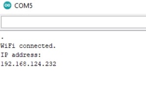
// Print local IP address and start web server
Serial.println("");
Serial.println("WiFi connected.");
Serial.println("IP address: ");
Serial.println(WiFi.localIP());
server.begin();
}
void loop(){
WiFiClient client = server.available(); // Listen for incoming clients
if (client) { // If a new client connects,
currentTime = millis();
previousTime = currentTime;
Serial.println("New Client."); // print a message out in the serial port
String currentLine = ""; // make a String to hold incoming data from the client
while (client.connected() && currentTime - previousTime <= timeoutTime) { // loop while the client's connected
currentTime = millis();
if (client.available()) { // if there's bytes to read from the client,
char c = client.read(); // read a byte, then
Serial.write(c); // print it out the serial monitor
header += c;
if (c == '\n') { // if the byte is a newline character
// if the current line is blank, you got two newline characters in a row.
// that's the end of the client HTTP request, so send a response:
if (currentLine.length() == 0) {
// HTTP headers always start with a response code (e.g. HTTP/1.1 200 OK)
// and a content-type so the client knows what's coming, then a blank line:
client.println("HTTP/1.1 200 OK");
client.println("Content-type:text/html");
client.println("Connection: close");
client.println();
// turns the GPIOs on and off
if (header.indexOf("GET /26/on") >= 0) {
Serial.println("GPIO 26 on");
output26State = "on";
digitalWrite(output26, HIGH);
} else if (header.indexOf("GET /26/off") >= 0) {
Serial.println("GPIO 26 off");
output26State = "off";
digitalWrite(output26, LOW);
} else if (header.indexOf("GET /27/on") >= 0) {
Serial.println("GPIO 27 on");
output27State = "on";
digitalWrite(output27, HIGH);
} else if (header.indexOf("GET /27/off") >= 0) {
Serial.println("GPIO 27 off");
output27State = "off";
digitalWrite(output27, LOW);
}else if (header.indexOf("GET /25/on") >= 0) {
Serial.println("GPIO 25 on");
output25State = "on";
digitalWrite(output25, HIGH);
} else if (header.indexOf("GET /25/off") >= 0) {
Serial.println("GPIO 25 off");
output25State = "off";
digitalWrite(output25, LOW);
}
// Display the HTML web page
client.println("<!DOCTYPE html><html>");
client.println("<head><meta name=\"viewport\" content=\"width=device-width, initial-scale=1\">");
client.println("<link rel=\"icon\" href=\"data:,\">");
// CSS to style the on/off buttons
// Feel free to change the background-color and font-size attributes to fit your preferences
client.println("<style>html { font-family: Helvetica; display: inline-block; margin: 0px auto; text-align: center;}");
client.println(".button { background-color: #4CAF50; border: none; color: white; padding: 16px 40px;");
client.println("text-decoration: none; font-size: 30px; margin: 2px; cursor: pointer;}");
client.println(".button2 {background-color: #555555;}</style></head>");
// Web Page Heading
client.println("<body><h1>ESP32 Web Server</h1>");
// Display current state, and ON/OFF buttons for GPIO 25
client.println("<p>GPIO 25 - State " + output25State + "</p>");
// If the output27State is off, it displays the ON button
if (output25State=="off") {
client.println("<p><a href=\"/25/on\"><button class=\"button\">ON</button></a></p>");
} else {
client.println("<p><a href=\"/25/off\"><button class=\"button button2\">OFF</button></a></p>");
}
client.println("</body></html>");
// Display current state, and ON/OFF buttons for GPIO 26
client.println("<p>GPIO 26 - State " + output26State + "</p>");
// If the output26State is off, it displays the ON button
if (output26State=="off") {
client.println("<p><a href=\"/26/on\"><button class=\"button\">ON</button></a></p>");
} else {
client.println("<p><a href=\"/26/off\"><button class=\"button button2\">OFF</button></a></p>");
}
// Display current state, and ON/OFF buttons for GPIO 27
client.println("<p>GPIO 27 - State " + output27State + "</p>");
// If the output27State is off, it displays the ON button
if (output27State=="off") {
client.println("<p><a href=\"/27/on\"><button class=\"button\">ON</button></a></p>");
} else {
client.println("<p><a href=\"/27/off\"><button class=\"button button2\">OFF</button></a></p>");
}
client.println("</body></html>");
// The HTTP response ends with another blank line
client.println();
// Break out of the while loop
break;
} else { // if you got a newline, then clear currentLine
currentLine = "";
}
} else if (c != '\r') { // if you got anything else but a carriage return character,
currentLine += c; // add it to the end of the currentLine
}
}
}
// Clear the header variable
header = "";
// Close the connection
client.stop();
Serial.println("Client disconnected.");
Serial.println("");
}
}
After running it, open the serial monitor and copy the IP address into a web browser.
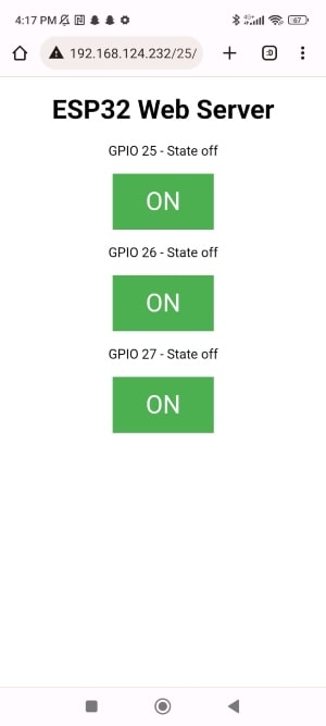
The result: