Mechanical Design and Machine Design
We chose to create a spice mixer for our group project! Arabic cuisine is known for its spiciness, and to cook any dish perfectly, you need to be skilled in blending the correct spices in the right proportions. Our machine takes care of all the mixing automatically! Initially, we programmed it to prepare one dish, but our ultimate goal is to have a collection of recipes that our machine can follow and prepare.
Planning:
When we began our research on available spice mixers in the market, we noticed that most of them were designed for industrial use and had large sizes. Therefore, we devised a plan to create a compact spice mixer that could be used in every household.
Our plan involved incorporating at least four types of spices commonly used in various dishes. We focused on three main dishes, each with its designated push button. For instance, if someone wanted dish number 1, they simply had to press the corresponding push button, and the machine would prepare the spice mix for that dish.
The key features of our machine included:
-
A linear system that allows the bowl to slide beneath the spice dispensers.
-
A dispensing system.
-
Electronics.
-
An integration system (frame).
By breaking down the components, we were able to allocate tasks and work in parallel with each other.
Dividing the components facilitated task allocation, enabling us to work concurrently.
-
The design and 3D printing of the dispensers and dispensing systems were assigned to Mohammad Shuqwara (myself) and Ahmad Jaara.
-
Rasha Khalifeh was responsible for the electronics design and integration system.
-
Ismael Qashou took charge of producing the integration system.
-
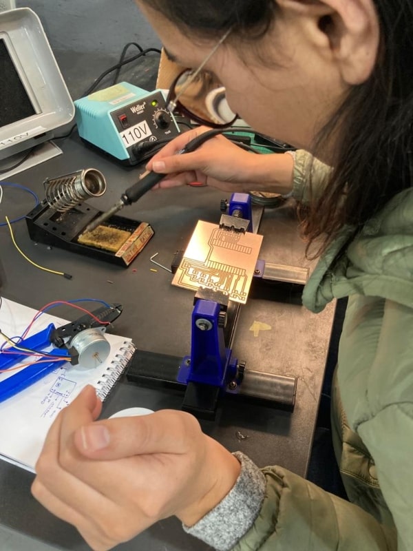
Lina Hudaib handled the soldering and assembly of the electronics.
-
Rasha Khalifeh was responsible for creating the video and presentation.
Integration System (Frame)
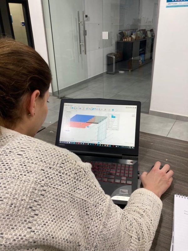
Rasha’s Contribution
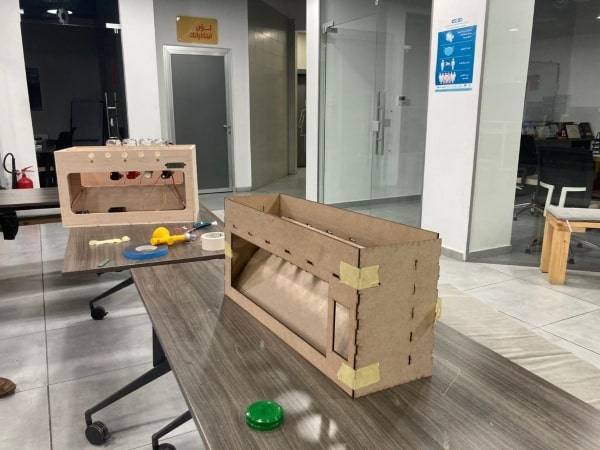
As someone who was new to Fusion360, designing the frame proved to be a challenge for me. Initially, I created a 2D frame that could be cut using a laser. After assembling it, we realized that certain modifications were necessary, so I went ahead and redesigned the frame accordingly.
I have sketched the initial frame for our systems integration box, incorporating hinges that will be press fitted into the side elements.
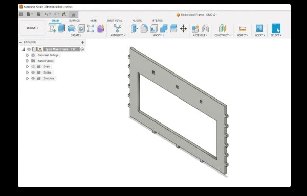
I made a duplicate of my frame to create two separate sections. One section is for the linear movement and dispensers, while the other section is meant to hide the motors, PCBs, and wires. I adjusted the opening to fit our specific requirements.
To make the modification, I moved the frame, selected the option to make a copy, and specified the desired distance. Before finalizing the distance, I measured our linear system and dispensers to ensure accuracy.
After several attempts, I discovered a crucial step in designing the frame.
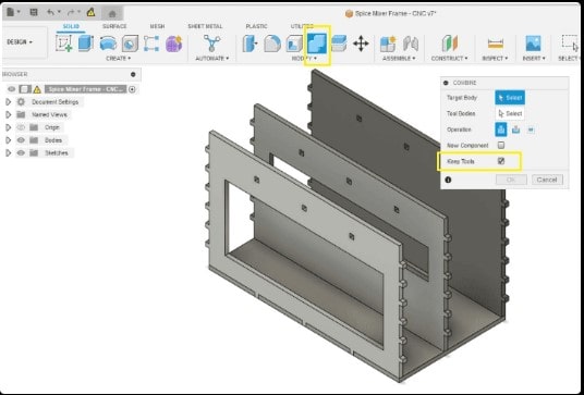
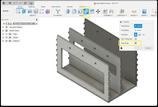
To create a surface that interlocks with the hinges you’ve created, follow these steps:
Go to Modify > Combine > Cut. Choose the targeted object and the tool object. Press “Keep Tool” - this step is crucial. Now, your new surface will have perforations exactly where the hinges are located! To ensure better fitting, I manually enlarged these openings by 0.05mm on each side. This adjustment makes it easier to press and assemble all the components together.
I repeated the process described above for multiple surfaces, including the upper, side, and lower parts of the frame. This ensured that each surface had interlocking features with hinges. Additionally, I created openings specifically for dispensers in the frame.
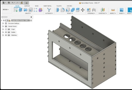
I incorporated the components created by my colleagues into the design and included the glass dispensers.
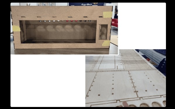
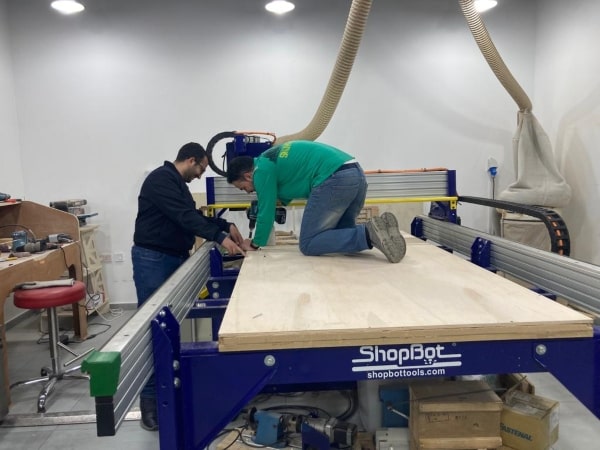
We initially created a prototype using a laser machine, and once we were satisfied with the design, we proceeded to fabricate the final version using a CNC machine.
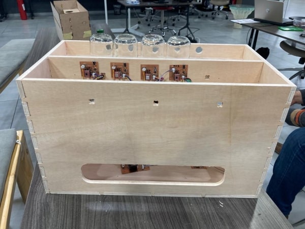
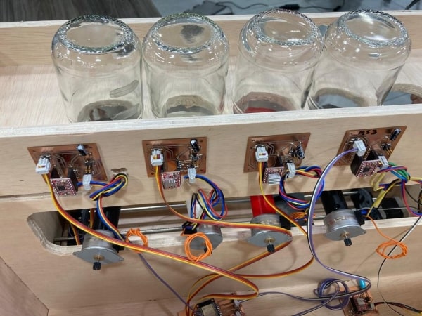
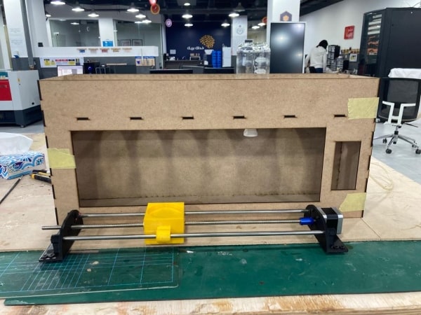
Below is the final design.
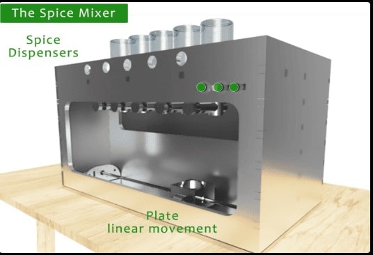
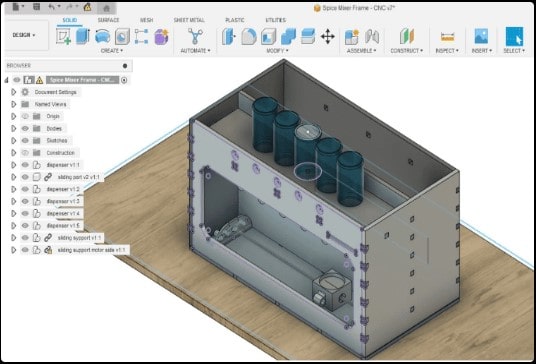
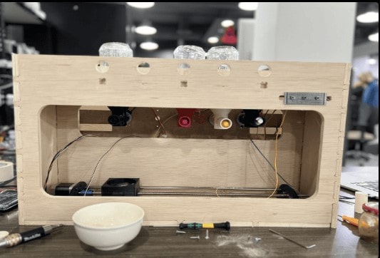
The picture below displays a Spice Mixer machine that has been put together with all its components: dispensers, linear movement mechanism, motors, and frame.
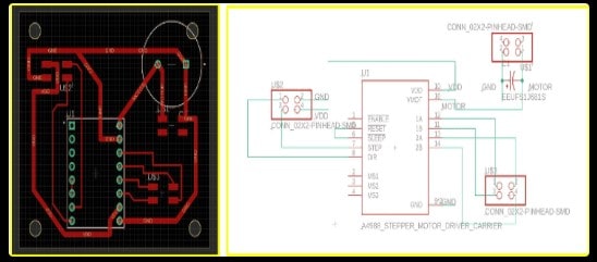
Circuit Design
For Rasha’s part in the circuit design, we chose to use stepper motors because we want to accurately count our steps and control the stopping positions of the mixing plate. In my circuit, I require the following components:
-
Stepper motors.
-
Stepper drivers.
-
Power supply.
-
ESP32 microcontroller to handle the operations.

There is only one circuit board connected to the motors and power supply.
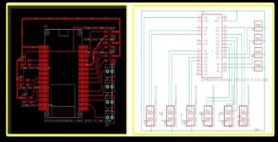
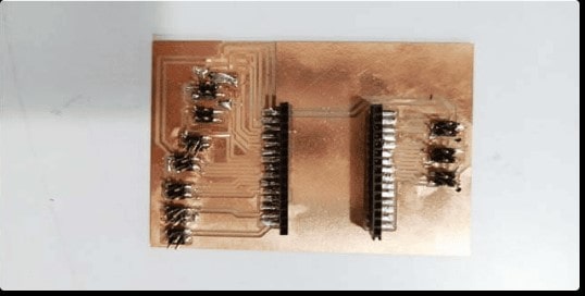
There are six circuit boards connected to stepper drivers, resistors, and a power supply.
As you can see, we had only through-hole resistors available at the lab, so we used a through-hole footprint for them. We took precautions to ensure there were no shorts by testing with a multimeter. Additionally, before soldering, we applied double-sided tape to the bottom of the resistor to prevent any movement.
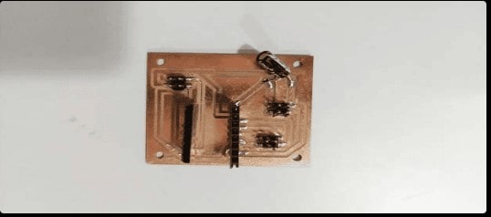
I assisted Rasha with soldering the circuit for this part.
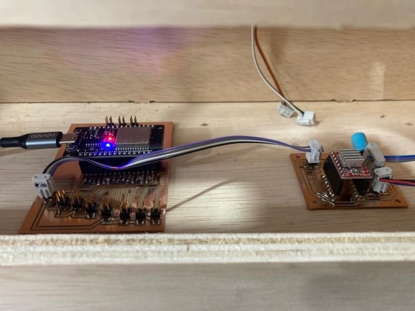
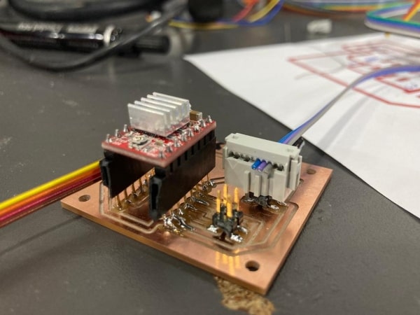
The final result:
Dispensing
Mohammad & Ahmad’s part
We faced some challenges when starting this part, so we divided it into the following components:
-
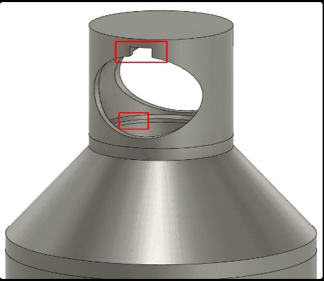
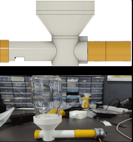
Cone: We used the revolve command to create the cone shape. Additionally, we incorporated a key feature to securely attach the housing of the Archimedes’ screw, and we added a rip to prevent powder leakage during dispensing.
-
Archimedes’ screw: This component is responsible for moving and dispensing the powder.
-
Archimedes’ screw housing: It provides support and holds the Archimedes’ screw in place.
-
The ring: This part helps stabilize the entire dispensing mechanism.
-
Coupler: The coupler connects the Archimedes’ screw to the motor for rotational movement.
By breaking down the dispensing part into these components, we were able to address the challenges and design a functional system.
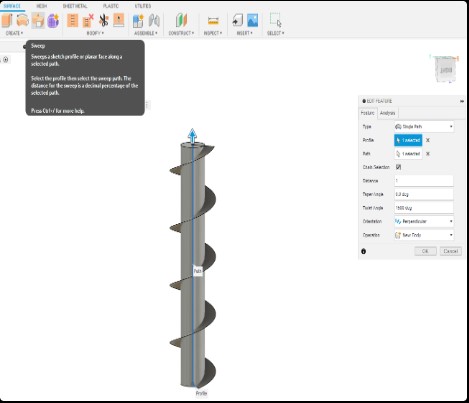
The next part, the Archimedes’ screw, was created using the sweep command in the surface tab. We applied this command to a cylinder that was previously made.
We designed the Archimedes’ screw housing with an opening specifically for dispensing spices. To ensure there is no leakage, we also included a cap to seal the housing securely.
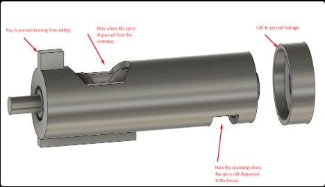
Additionally, we created a sealing piece to ensure that all the dispensed spices would enter without any leakage. This sealing piece helps maintain a tight and secure connection to prevent any unwanted spillage during the dispensing process.
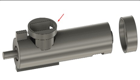
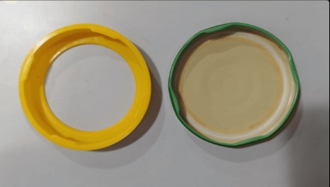
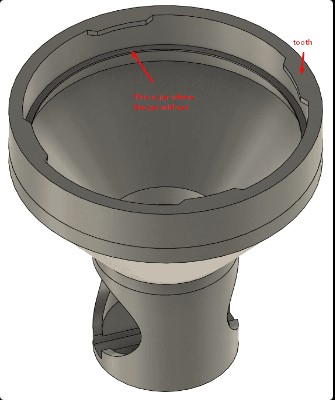
The design of the ring proved to be a bit challenging. Our goal was to ensure a secure connection between the ring and the jar without any leakage. To achieve this, we took the original cap of the jar and attempted to reverse engineer it. After numerous attempts and iterations, we successfully created a tooth profile that fits snugly with the teeth of the jar. This allows for a tight and leak-free connection between the ring and the jar.
After conducting tests, we proceeded to attach the ring to the cone and combined them together. This integration ensures the proper functioning and alignment of the components within the dispensing mechanism.
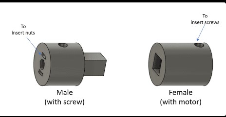
The final part involves creating a coupling between the motor shaft and the Archimedes’ screw. For this purpose, we designed two pieces that will be attached to their respective shafts using screws. These pieces ensure a secure connection and proper transfer of rotational motion from the motor to the Archimedes’ screw, allowing for efficient dispensing of the spices.
Once all the parts were designed, we proceeded to 3D print them. The fabricated parts were printed with the following settings:
-
Layer Height: 0.2mm.
-
Infill Percentage: 50%.
-
Adhesion: Brim with a diameter of 5mm.
-
Print Speed: 60 mm/s.
-
First Layer Speed & Brim Speed: 30 mm/s.
-
Build Plate Temperature: 60°C.
-
Support: Used during the printing process.
These settings were chosen to ensure accurate and reliable fabrication of the parts, providing the desired strength and functionality for the Spice Mixer machine.
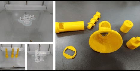
Final result:

Linear System
Lina’s part
The objective of the linear system is to go back and forth, and stop under the each dispenser for a set of time to collect the spices, first we go through the design first and on fusion 360.
This plate will move in a straight line and stop under the desired spice, then continue moving.
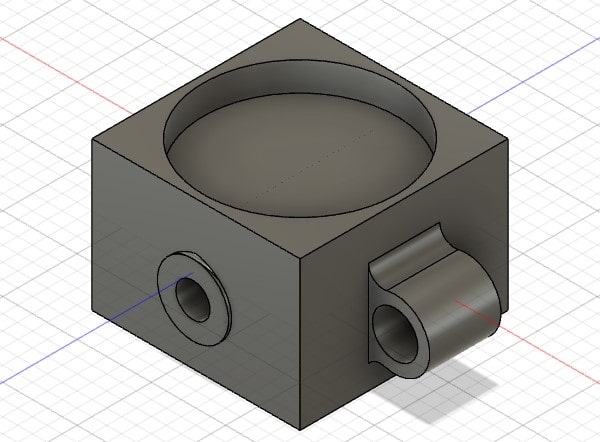
We need three parts for this mechanism. The first part will be the moving component, on which we will place the plate. This part will move along the axis, and to achieve this movement, I will use a screw and its nut.
To ensure that the plate moves in a straight line, we will use two rods and two linear bearings to reduce friction between the part and the rods.
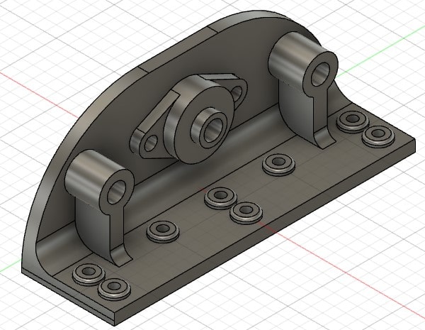
For the motor component, we plan to use a stepper motor to rotate the screw, which will cause movement in the plate. To connect the motor shaft with the screw, we originally intended to use a rigid coupler, but if we have a flexible coupler we would use it instead. This will allow for some flexibility in alignment.
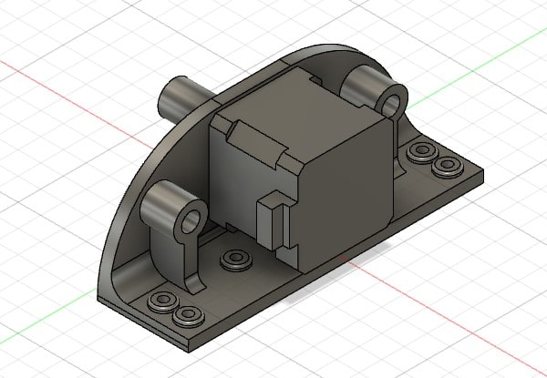
On the other side, where the block bearing is located, it will assist with aligning the system. we have installed two limit switches on either side. The limit switch is used to provide a signal to stop, start the operation of a motor when an object reaches a specific position.
The settings for 3D printing will be a layer height of 0.2mm and an infill of 20%. Additionally, I conducted several tests to ensure that the linear bearing fits properly on the sliding part.
Afterward, I began coding to achieve the desired linear movement for the Spice Mixer machine.

Coding
We list the two codes, one for the linear system and the other for the dispensing system:
First we tested the linear system through this code:
int ml_pin_step = 15;
int ml_pin_dir =2;

int dir = 0;

int sw_start_pin = 17;
int sw_end_pin = 4;

void setup() {
  pinMode(ml_pin_step, OUTPUT);
  pinMode(ml_pin_dir, OUTPUT);
  pinMode(sw_start_pin, INPUT_PULLUP);
  pinMode(sw_end_pin, INPUT_PULLUP);

  Serial.begin(9600);
}

void loop() {

if(digitalRead(sw_start_pin) == 0){
  dir = LOW; //forward
  delay(100);
}

if(digitalRead(sw_end_pin) == 0){
  dir = HIGH; //back
  delay(5000);
}

Serial.println(dir);
digitalWrite(ml_pin_dir, dir); //back

int time = 2100;
digitalWrite(ml_pin_step, HIGH);
delayMicroseconds(time);
digitalWrite(ml_pin_step, LOW);
delayMicroseconds(time);
}
This code controls the linear system of the Spice Mixer. It utilizes a stepper motor and limit switches. The code continuously monitors the status of the limit switches. When the start switch is pressed, the motor moves the linear system forward. If the end switch is pressed, the motor moves the linear system backward after a 5-second delay. The code generates step pulses to control the motor’s movement and outputs the motor direction through the serial monitor.
The integrated code for all systems:
//Pins diclirtion
#define LinearMotorDir 2
#define LinearMotorStep 15
//******************//
#define LimitSwich1 16
#define LimitSwich2 17
//******************//
#define Dis1Dir 14
#define Dis1Step 13
#define Dis2Dir 26
#define Dis2Step 27
#define Dis3Dir 33
#define Dis3Step 25
#define Dis4Dir 21
#define Dis4Step 19
#define Dis5Dir 18
#define Dis5Step 5
//******************//
#define PushButtonModeM 4

#define PushButtonModeK 22

#define PushButtonModeR 23

//******************//

#define StepsDelayUS 1000
#define IntervalDelaymS   3000

//******************//
bool LimitSwich1State = 0;
bool LimitSwich2State = 0;
//******************//
unsigned int Dis1M=10;
unsigned int Dis1K=10;
unsigned int Dis1R=10;
//******************//
unsigned int Dis2M=10;
unsigned int Dis2K=10;
unsigned int Dis2R=10;
//******************//
unsigned int Dis3M=10;
unsigned int Dis3K=10;
unsigned int Dis3R=10;
//******************//
unsigned int Dis4M=10;
unsigned int Dis4K=10;
unsigned int Dis4R=10;
//******************//
unsigned int Dis5M=10;
unsigned int Dis5K=10;
unsigned int Dis5R=10;
/******************//


void SetHome(){
digitalWrite (LinearMotorDir,HIGH);
while(digitalRead(LimitSwich1)){
digitalWrite(LinearMotorDir,HIGH);
delayMicroseconds (StepsDelayUS);
digitalWrite(LinearMotorDir,LOW);
      }
  digitalWrite(LinearMotorDir,LOW);
  }


void setup() {
pinMode(LinearMotorStep,OUTPUT);
pinMode(LinearMotorDir,OUTPUT);
pinMode(Dis1Step,OUTPUT);
pinMode(Dis1Dir,OUTPUT);
pinMode(Dis2Step,OUTPUT);
pinMode(Dis2Dir,OUTPUT);
pinMode(Dis3Step,OUTPUT);
pinMode(Dis3Dir,OUTPUT);
pinMode(Dis4Step,OUTPUT);
pinMode(Dis4Dir,OUTPUT);
pinMode(Dis5Step,OUTPUT);
pinMode(Dis5Dir,OUTPUT);
//******************//
pinMode(PushButtonModeM,INPUT);
pinMode(PushButtonModeK,INPUT);
pinMode(PushButtonModeR,INPUT);
pinMode(LimitSwich1,INPUT);
pinMode(LimitSwich2,INPUT);
}

void loop() {
SetHome();
if(digitalRead(PushButtonModeM)==HIGH){
    SetHome();
    Maqloba();
}
else if (digitalRead(PushButtonModeK)==HIGH){
    SetHome();
    Kabsa();
}
else if (digitalRead(PushButtonModeR)==HIGH){
    SetHome();
    Rice();
}

}
This code integrates the control of all systems within the Spice Mixer machine. It includes pin assignments for components such as motors, limit switches, and push buttons. The code establishes delay intervals and initializes variables for spice quantities. In the main loop, it continuously checks the state of the push buttons. When a specific push button is pressed, the corresponding recipe function is executed. Within each recipe function, the linear system moves to the desired position using the SetHome function. Then, the code controls the dispensing of spices by generating step pulses for each dispenser motor. The spice quantities are determined by the values assigned to the respective variables. Once each recipe is completed, the linear system returns to the initial position using the SetHome function.
The interface presented a challenge, but we successfully completed the assembly. It is important to note that there is room for improvement in the final result. Finally, here is the video showcasing the functioning of the completed machine.

Conclusion:
In conclusion, our Spice Mixer project involved the design and development of a compact spice mixing machine for home use. We successfully divided the tasks among our team members and executed our respective parts. This included designing and 3D printing components for the dispensing system, creating a frame using Fusion360, developing circuit designs for motor control, and assembling all the parts together. Additionally, we wrote code to control the linear system’s movement and integrated it with the dispensing system.
The end result was a functional Spice Mixer machine capable of accurately dispensing spices for specific recipes. The project showcased our team’s collaboration and the utilization of mechanical, electronic, and programming skills to create an automated spice mixing machine.
Looking ahead, there are several potential future improvements and enhancements we could consider. These may include the development of a recipe database, adjustable spice intensity, integration with smartphones for remote control, voice command functionality, smart ingredient detection, multi-language support, nutritional information display, simplified cleaning processes, cloud syncing and sharing capabilities, and expandable spice dispensers.
We would like to express our sincere appreciation and gratitude to our instructor, Emma. Her guidance, expertise, and support have been instrumental throughout our Spice Mixer project. Her dedication to teaching, prompt assistance, and valuable feedback have significantly contributed to our success. We are grateful for the knowledge and skills we have gained under her mentorship. Emma’s passion for the subject matter and her commitment to our learning have inspired us to strive for excellence. We are truly thankful for her exceptional instruction and the positive impact she has had on our project.
Here you can download the spice mixer frame.
Here you can download the Dispensing system.
Here you can download the mother PCB.
Here you can download the motor PCB.
Here you can download the codes.