Input Devices
Group assignment
For the group assignment, we will test two input devices -analog and digital- and monitor the voltage changes using a multimeter.
The light sensor circuit:
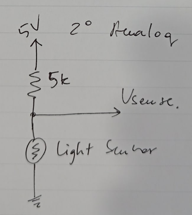

When using the light sensor as an analog input device, the voltage decreases with stronger light due to the light’s impact on the resistance of the sensor. This change in resistance subsequently affects the current. It is important to note that the effect of light is observed on the material of the sensor rather than on the electrons themselves.
The push button circuit:
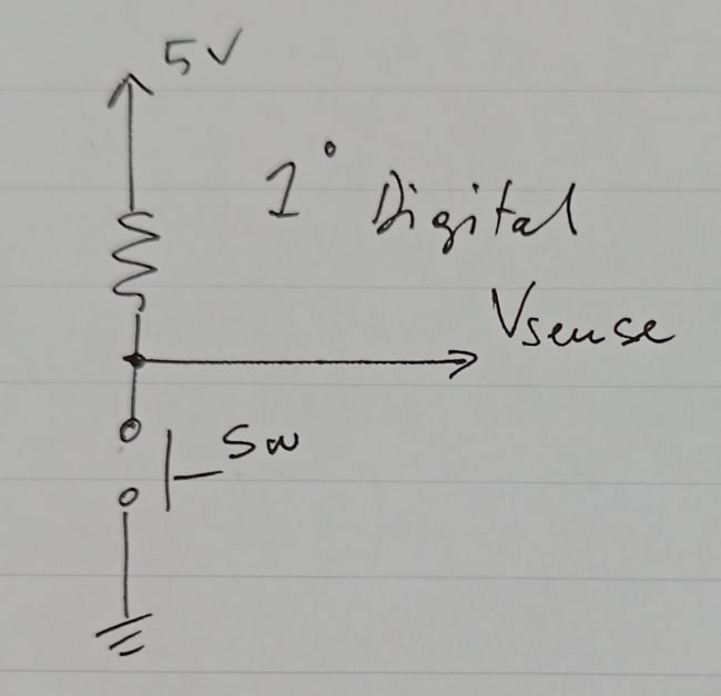

Similarly, the push button can also be used as a digital input device, where its output voltage is either high (around 5 volts) or low (around 0 volts), depending on whether the button is pressed or not.
Now, let’s move on to my assignment.
This week, I’ve started thinking about my final project circuit, so I did something closely related to my project.
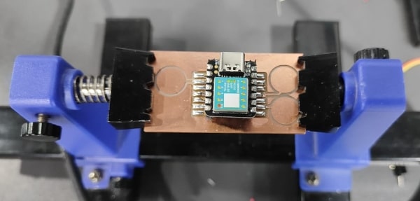
My final project relies heavily on the capacitive touch sensor, as I will be using its signal to control all the output devices. To achieve this, I have started designing my board using the Seeed Studio XIAO SAMD21 microcontroller.
Eagle
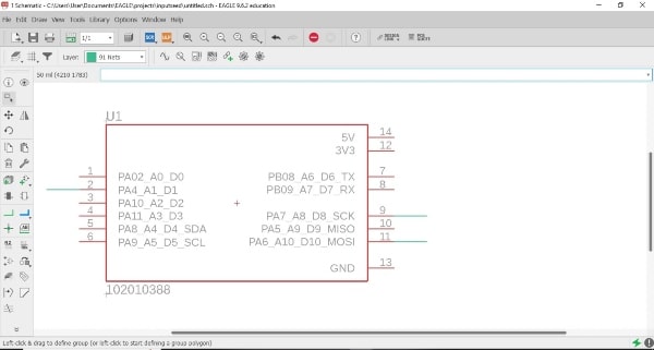
I started designing my circuit on Eagle.
I began searching for a footprint for the MCU I wanted to use, but couldn’t find one with rectangular pads - they all had holes. So, I downloaded the closest library I could find and started editing it in Eagle, here is the link for it.
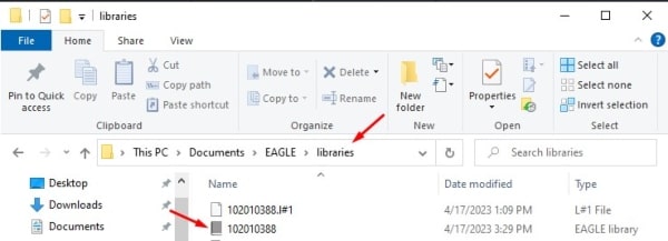
Download the library and place it in the library folder on your computer.
Once you’ve done that, open Eagle and double-click on the library that you want to edit.
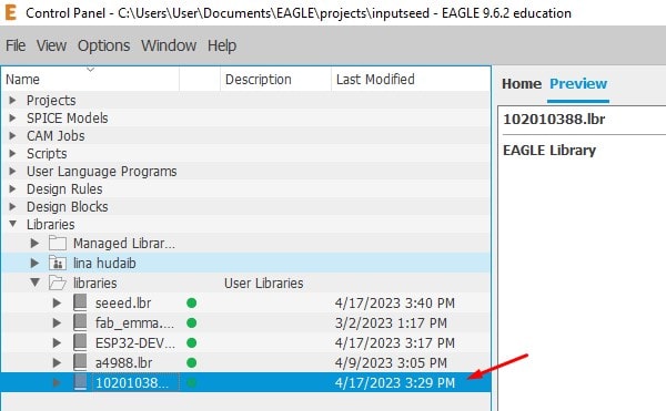
This interface will appear.
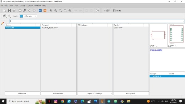
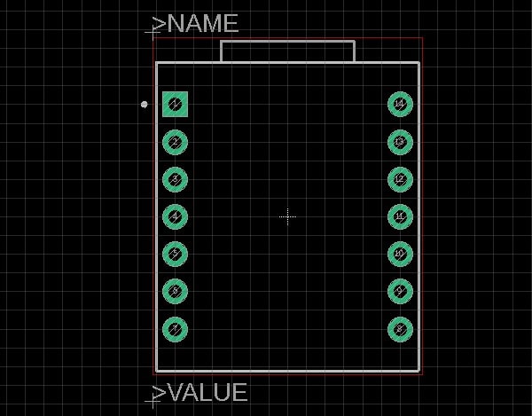
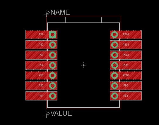
This is the footprint with the holes that we will edit.
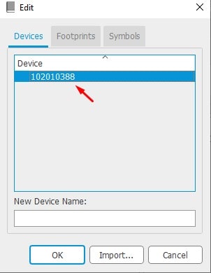
Now we need to go to the device and disconnect the pins with holes so that we can edit them.
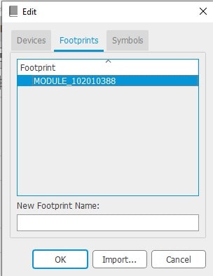
Select the device that you want to edit.
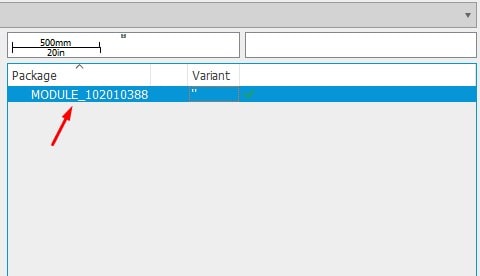
Next, you need to select the module that you will be working on
To make it easier, take a screenshot or else you will have to double-check which pin is the ground, 3v3, etc.
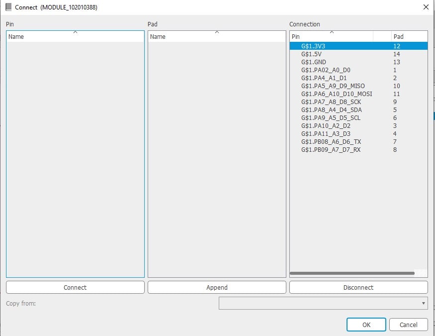
Now, disconnect all of the pins. Press Ok.
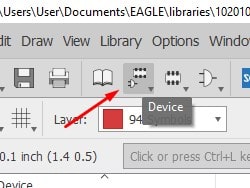
To begin editing, click on Footprint.
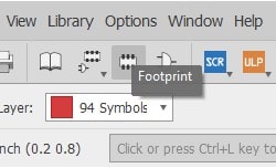
Next, select the module again.
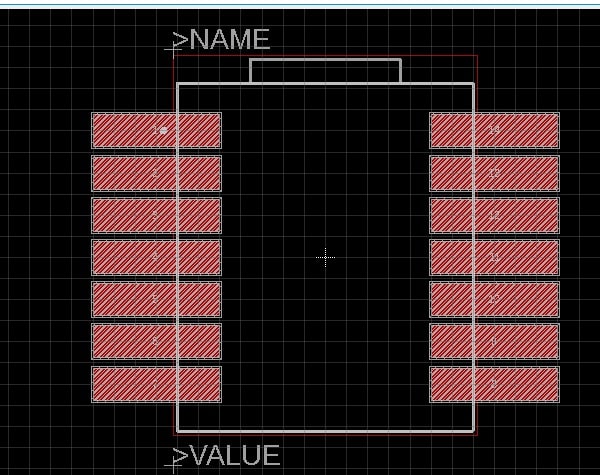
Navigate to the top layer where you will create the Smd.
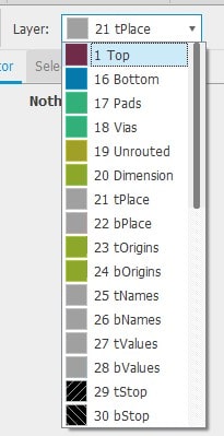
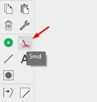
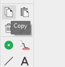
Since I want Smd instead of holes, I will use this option.
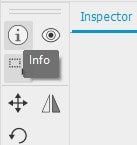
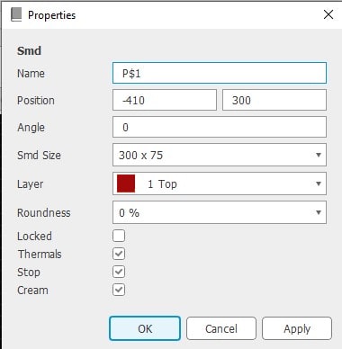
Click on info to modify the name, position, and SMD pad size.
Copy it and paste it above all of the holes.
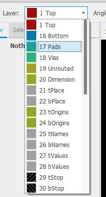
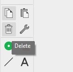
Afterward, delete the holes by navigating to the pads layer.
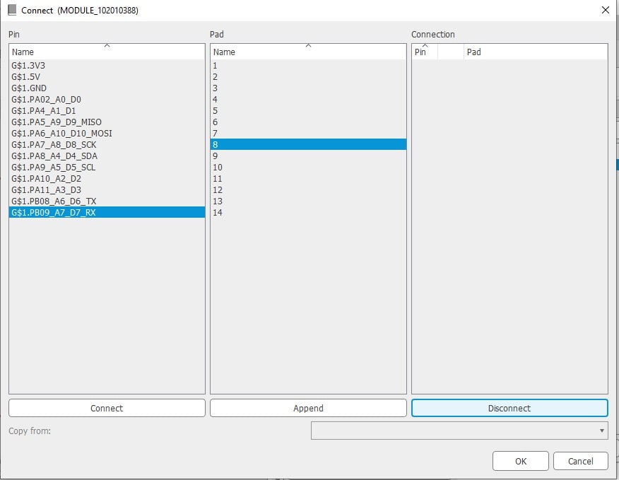
Return to the device and connect the pins as shown in the screenshot that you took earlier.
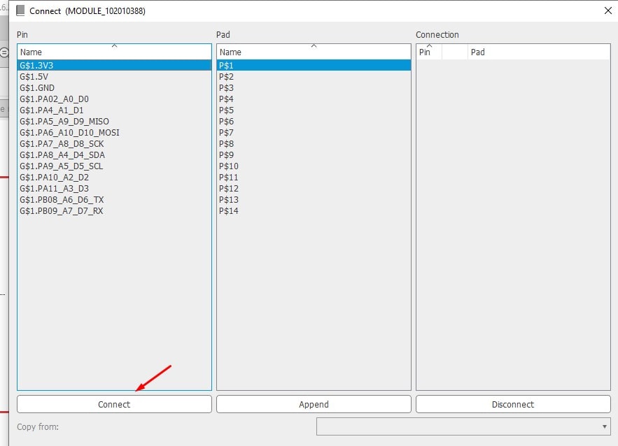
Finally, you can save the changes and begin using it.
As this MCU has a built-in touch sensor, I will simply attach a copper plate to the pin to enable touch detection.
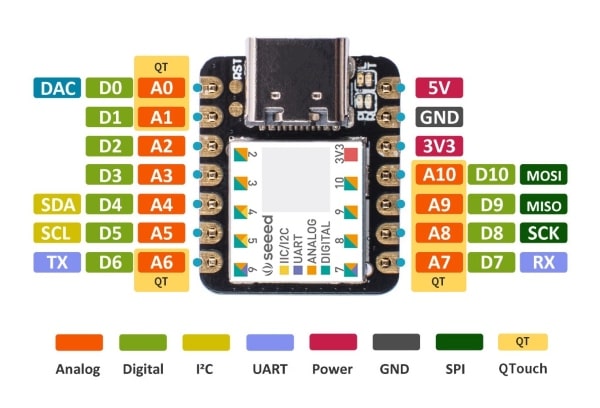
I will choose three pins: A8, A10, and A1.
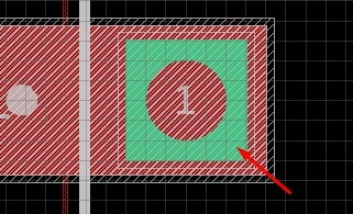
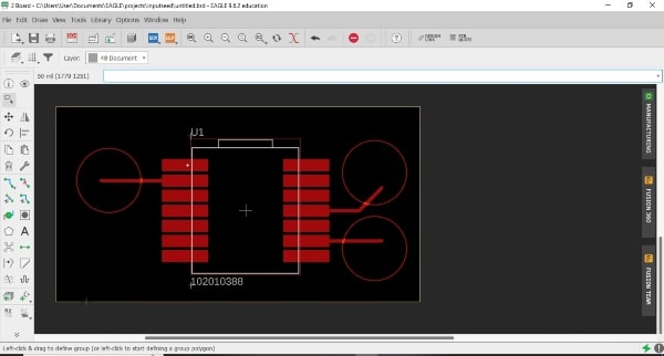
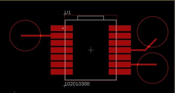
Then, I will draw the circles on the board layout.
Here you can download the schematic file.
Here you can download the board file.
To convert the layout board to an image, and then edit it on GIMP.


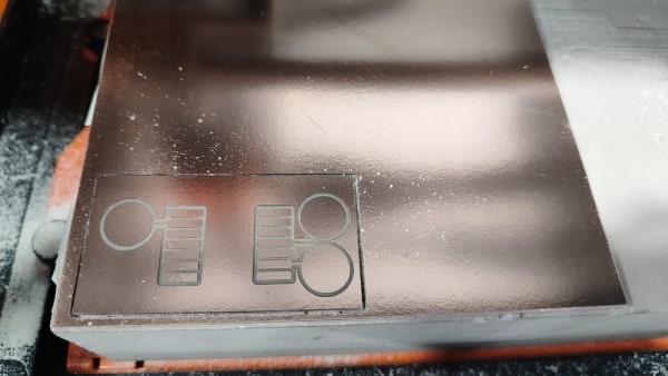
Miling and soldering
After that, I began the milling process. For a detailed breakdown of the steps I took in this part, please refer to the electronics production week.
The next step is the soldering process.
After I finish the board, it is time to code it.
Coding
I found a code on this website that closely resembles the one I want to use for my code.
We’ll begin by downloading the library, Adafruit_FreeTouch to learn how to download the library, please refer to the output device week.
The code:
#include "Adafruit_FreeTouch.h"
Adafruit_FreeTouch qt_1 = Adafruit_FreeTouch(A1, OVERSAMPLE_4, RESISTOR_50K, FREQ_MODE_NONE);
Adafruit_FreeTouch qt_2 = Adafruit_FreeTouch(SCK, OVERSAMPLE_4, RESISTOR_50K, FREQ_MODE_NONE);
Adafruit_FreeTouch qt_3 = Adafruit_FreeTouch(MOSI, OVERSAMPLE_4, RESISTOR_50K, FREQ_MODE_NONE);

void setup() {

 Serial.begin(115200);

}

int qt_Threshold = 850;

void loop() {
  int qt1 = 0;
  int qt2 = 0;
  int qt3 = 0;

  if (! qt_1.begin())
    Serial.println("Failed to begin qt");
  if (! qt_2.begin())
    Serial.println("Failed to begin qt");
  if (! qt_3.begin())
    Serial.println("Failed to begin qt");


   qt1 = qt_1.measure();

  if (qt1 >= qt_Threshold) {
   Serial.println("Touched1");
   delay (2000);
  }
  else {
    Serial.println("Untouched1");
    delay (2000);

  }

    qt2 = qt_2.measure();

  if (qt2 >= qt_Threshold) {
    Serial.println("Touched2");
    delay (2000);

  }

   else {
    Serial.println("Untouched2");
    delay (2000);

  }

  qt3 = qt_3.measure();

  if (qt3 >= qt_Threshold) {
    Serial.println("Touched3");
    delay (2000);

  }
   else {
    Serial.println("Untouched3");
    delay (2000);
  }
}
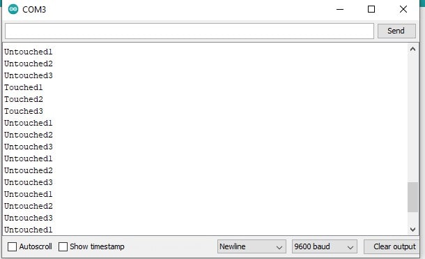
In this code, the first step is to define the variables that will read the signals from the pins, as well as to assign the pins to be used. These variables are then initialized with a starting value of zero. A condition is included to verify that all pins are working correctly. Next, the value read by the capacitive sensor is compared to the qt_Threshold using a conditional statement. Based on the conditional statement, the program will then print on the serial monitor whether the capacitive sensor has been touched or not.
The result when I am touching different capacitors:
#include "Adafruit_FreeTouch.h"
Adafruit_FreeTouch qt_1 = Adafruit_FreeTouch(A1, OVERSAMPLE_4, RESISTOR_50K, FREQ_MODE_NONE);
Adafruit_FreeTouch qt_2 = Adafruit_FreeTouch(SCK, OVERSAMPLE_4, RESISTOR_50K, FREQ_MODE_NONE);
Adafruit_FreeTouch qt_3 = Adafruit_FreeTouch(MOSI, OVERSAMPLE_4, RESISTOR_50K, FREQ_MODE_NONE);
void setup() {
  Serial.begin(115200);

}

int qt_Threshold = 850;

void loop() {
  int qt1 = 0;
  int qt2 = 0;
  int qt3 = 0;

  if (! qt_1.begin())
    Serial.println("Failed to begin qt");
  if (! qt_2.begin())
    Serial.println("Failed to begin qt");
  if (! qt_3.begin())
    Serial.println("Failed to begin qt");

    qt1 = qt_1.measure();
    qt2 = qt_2.measure();
    qt3 = qt_3.measure();

    Serial.print(qt1);
    Serial.print(",");
    Serial.print(qt2);
    Serial.print(",");
    Serial.println(qt3);

}
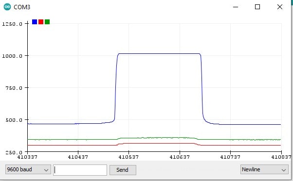
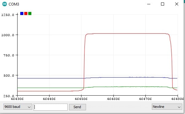
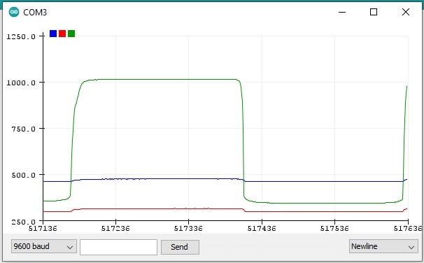
Here is the same code as before, but now the signal will be plotted.
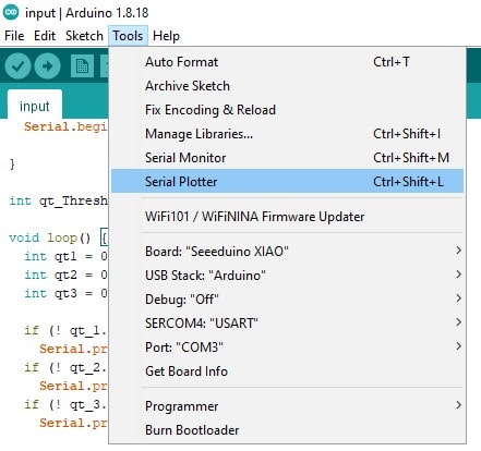
The result when I am touching different capacitors: