Electronics Design
Electrical Instruments
This week, I will study and become much more familiar with three instruments in the electronics section: the multimeter, oscilloscope, and power source.
Multimeter
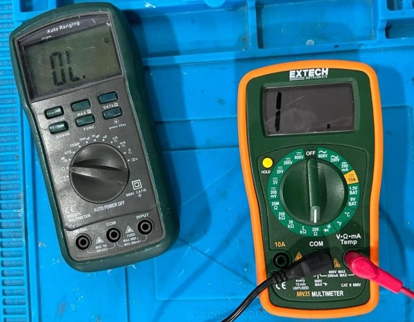
A multimeter is an electronic measuring instrument that can measure multiple electrical properties such as voltage, current, and resistance.
Set the multimeter to the appropriate mode: Depending on what you want to measure. Most multimeters have a dial or button to switch between voltage, current, and resistance modes.
You should be aware that a multimeter has different measurement ranges, and it is important to set the selector to the appropriate range in order to obtain accurate readings. Otherwise, the display may show either “1” or “OL”, indicating an overload condition.
Depending on what you want to measure, you may need to connect the multimeter in series or in parallel with the circuit.
-
Measure voltage: To measure voltage, connect the multimeter in parallel with the circuit. Ensure that the multimeter is set to the voltage mode and select the appropriate range. Touch the multimeter leads to the positive and negative terminals of the circuit to measure the voltage across them.
-
Measure current: To measure current, connect the multimeter in series with the circuit. Ensure that the multimeter is set to the current mode and select the appropriate range. Touch the multimeter leads to the circuit in series with the current flow to measure the current.
-
Measure resistance: To measure resistance, disconnect the circuit from any power source. Ensure that the multimeter is set to the resistance mode and select the appropriate range. Touch the multimeter leads to the two ends of the component or wire whose resistance you want to measure.
Typically, a multimeter is employed to verify continuity between two wires, particularly after soldering. It is also utilized to measure the voltage output from pins of a microcontroller, and can be used to check the polarity of an LED.
Oscilloscope
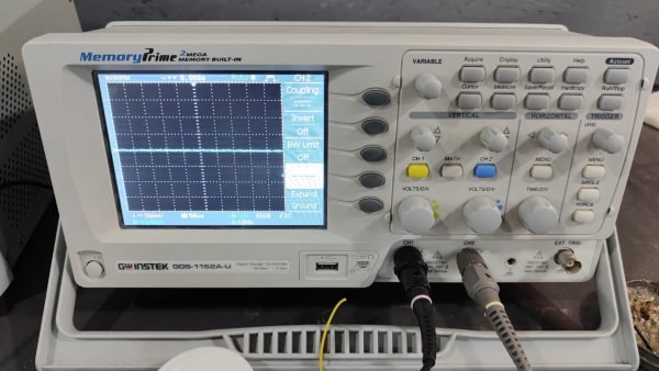
An oscilloscope, is a type of electronic test instrument used to visualize and analyze the waveform of electrical signals. It displays the amplitude, frequency, and time-based variations of signals as a graph on a screen.
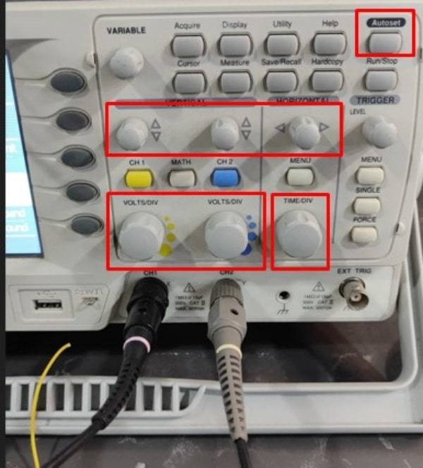
The time/division control on an oscilloscope adjusts the horizontal scale of the display, determining the time duration represented by each division. This control allows users to zoom in or out on the signal, allowing for more detailed analysis of signal behavior.
The voltage control, on the other hand, adjusts the vertical scale of the display, determining the voltage represented by each division. This control allows users to measure the amplitude of the signal and to ensure that the signal is within the desired voltage range.
When the “Autoset” button is pressed, the oscilloscope will analyze the input signal and adjust the settings to optimize the display. This may include adjusting the vertical scale to fit the signal within the display area, adjusting the horizontal scale to show multiple periods of the signal.
We can also adjust the position of the signal on the screen and control its placement using the controls provided on the oscilloscope.
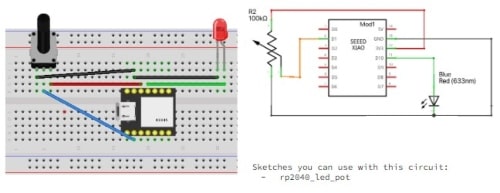
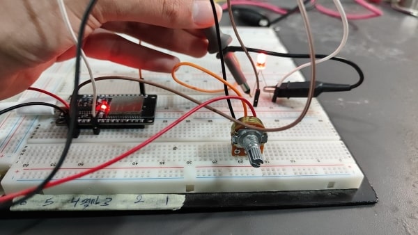
To test the oscilloscope, I will run this code and observe the resulting waveform on the oscilloscope screen. The circuit consists of a potentiometer and an LED, I will control the LED light intensity using the potentiometer in the circuit.
By turning the potentiometer knob, the resistance of the potentiometer changes, which in turn changes the voltage at the analog pin. This change in voltage is read by the Arduino as an analog value, which is then mapped to control the LED brightness. As a result, adjusting the potentiometer allows you to vary the brightness of the LED.
The signal on the oscilloscope in this case would represent the voltage level at the analog pin of the Arduino over time. Since we are using a potentiometer to control the LED brightness, the signal would show a varying voltage level based on the position of the potentiometer knob.
The code:
int ledPin = 16;
int sensorPin = 36;
int sensorValue=0;
int outputValue=0;
const int freq = 5000;
const int ledChannel = 0;
const int resolution = 8;

void setup() {

  pinMode(ledPin, OUTPUT);
  pinMode(sensorPin, INPUT);
  ledcSetup(ledChannel, freq, resolution);
  ledcAttachPin(ledPin, ledChannel);

  Serial.begin(9600);

}

void loop() {

  sensorValue = analogRead(sensorPin);
  outputValue = map(sensorValue, 0, 4095, 0, 255);
  ledcWrite(ledChannel, outputValue);

  Serial.println(outputValue);

delay(100);
}
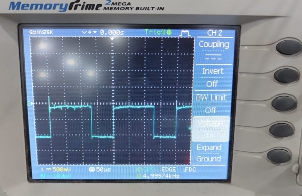
The result:
Power source
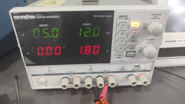
A power source, also known as a power supply, is an electronic device that converts electrical power from a source, such as a battery.
We can control the voltage output of a power source and also determine the maximum amount of current that can be supplied to a circuit by setting the current limit.
Eagle
Okay, now I will start with electronics design. The program I will use is Eagle.
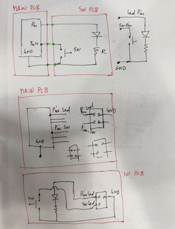
I am planning to design two PCBs for my final project. The first one will be the main PCB that includes the MCU. This main PCB will control the other PCB.
So basically, I will design two PCBs. The first PCB will contain the microcontroller unit (MCU) along with four connectors, each having three wires. These connectors will be connected to two pins, one for input and the other for output and a ground. The other four PCBs will each have a connector to accommodate a switch for the input signal and an LED for the output signal and ground.
Designing this PCB will allow me to become more familiar with Eagle.
How to Add Library
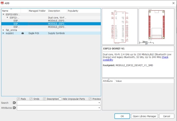
If I need a component like the MCU (in this case, the ESP32), and it is not in the Eagle library, I will need to add the library for the ESP32 in order to use it in my design.
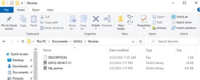
I will download the library for the ESP32 and place it in the “Libraries” folder within the “EAGLE” directory in my “Documents” folder.
After downloading the library, I will open Eagle and go to the control panel, then select “Libraries” and activate the library I downloaded.
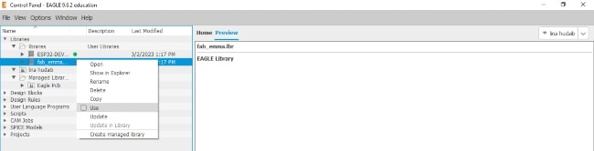
The library and its components are now available for use.
Schematic Editor and Board Layout Editor
Before we begin designing the PCB, it is important to understand the difference between the Schematic Editor and the Board Layout Editor.
-
Schematic Editor: This is where you can create and edit the schematic diagram of your PCB design, and add components and connections.
-
Board Layout Editor: This is where you can design and layout the physical PCB, including placing components and routing traces between them.
Designing Process
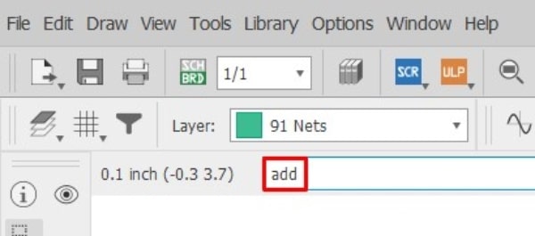
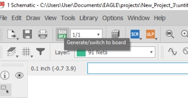
Now, to create a new project, please follow the picture below.
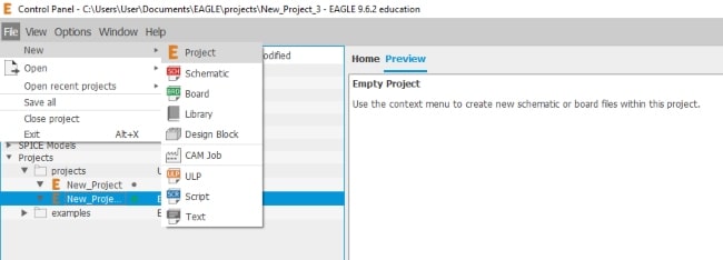
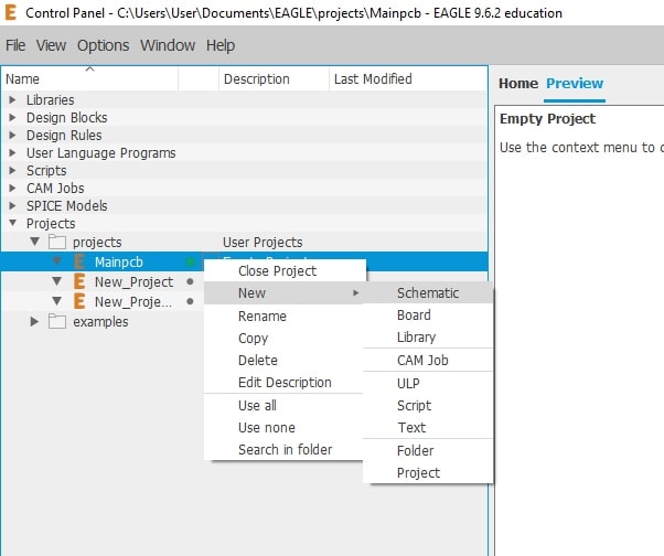
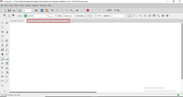
The red box indicates where we will enter the command.
Let’s discuss the two PCBs that I will be designing this week before starting.
When I was thinking about my final project PCB, I realized that I would start with a very simple PCB and develop it. So, I began with the main PCB, which had the MCU and four connectors to control other PCBs that are far away from it. Before starting with Eagle, let’s begin with pen and paper.
Now let’s begin designing the main PCB. If you want to add a component, write “add” in the command box and choose what you want.
In Eagle, a footprint refers to the physical layout and configuration of a component on a PCB. When selecting a component, it is important to choose a suitable footprint that matches the physical dimensions and pin configuration of the component you have.
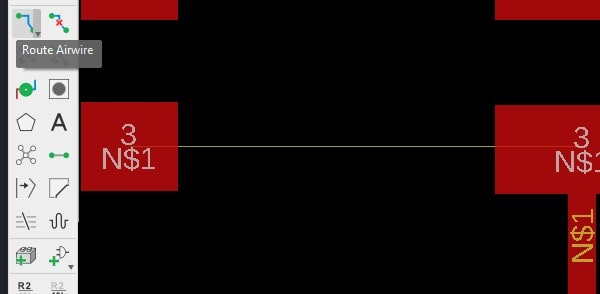
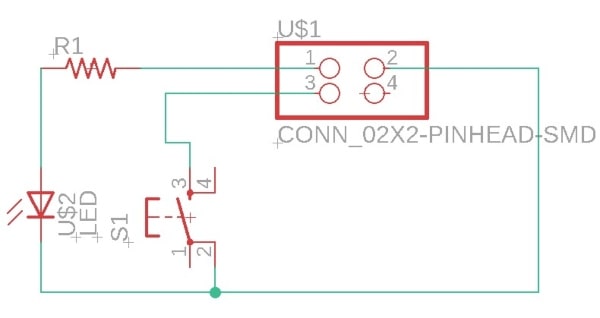
To connect components, type “wire” in the command box and connect them together.
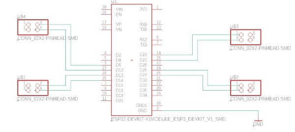
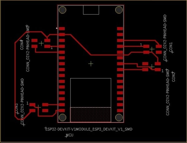
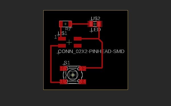
After finishing the circuit design, it is time to generate the PCB layout.
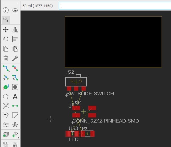
Alright, now I will move all the components onto the layout within the yellow box and organize them. Then, I will use the “Route Airwire” commands to create the necessary connections.
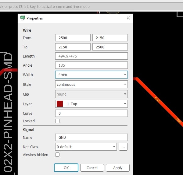
Before we conclude the design, there is one final thing to consider, the wire thickness. I will set it at 0.4mm. If you need to modify it, simply type “info” in the command box and select the wire you wish to adjust and edit the width.
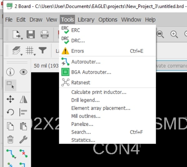
There is one final command I’d like to discuss, which is DCR.
DCR stands for Design Rule Check. It is a feature that checks your PCB design against a set of predefined rules to ensure that your design meets certain requirements. These rules can include things like minimum trace width, minimum spacing between components, and clearance requirements for different types of signals. Running a DRC can help you catch design errors early on, before you send your design to manufacturing.
I have set these conditions so that the program can take them into account when I execute the error command.
![]()
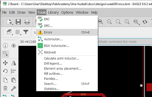
Check for errors using the “Errors” command.
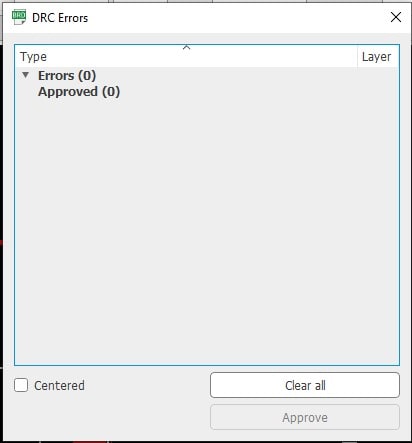
I repeated all the necessary steps to design the other PCB.
Finally, I am done.
Here you can download the two PCBs.