Output Device
Group assignment
For the group assignment, we are supposed to test some output devices and see how much current they will take. I will start with devices that run on 3 volts.
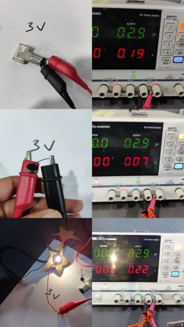
- Air pump:
Runs on 2.9 volt and takes .19 Amber, power 2.9*.19 =.551 Watt
- Vibrator motor:
Runs on 2.9 volt and takes .07 Amber, power 2.9*.07 =.203 Watt
- Led:
Runs on 2.9 volt and takes .22 Amber, power 2.9*.22 =.638 Watt
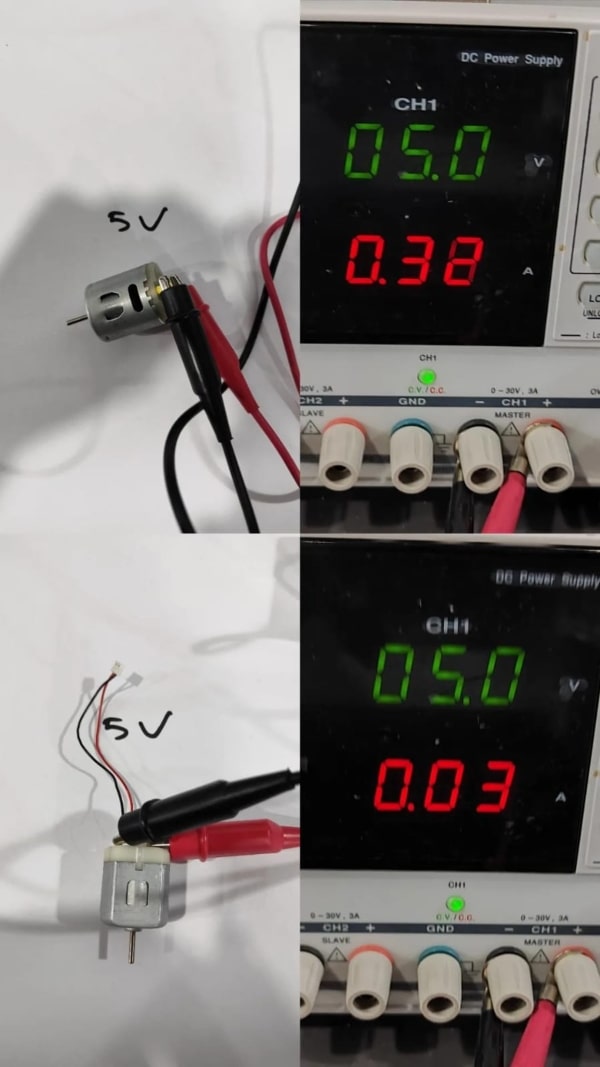
Afterwards, we tested two DC motors which run on 5 volts. The first motor drew 0.03 amperes and consumed 0.15 watts of power, while the second motor drew 0.32 amperes and consumed 1.6 watts of power.
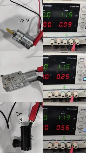
For the last test, we used two DC motors that run on 12 volts. The first motor drew 0.25 amperes and consumed 2.975 watts of power, while the second motor drew 0.09 amperes and consumed 1.071 watts of power.
The third device we tested was a water pump that drew 0.56 amperes and consumed 6.664 watts of power.
The formula used to calculate power is P=VI, where P represents power, V represents voltage, and I represents current.
Individual assignment
Eagle
I am planning to test two output devices this week, the speaker and NeoPixel LED. My intention is to control both of them using a push buttons.
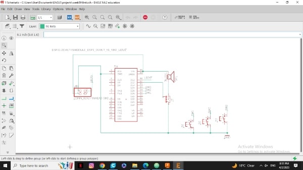
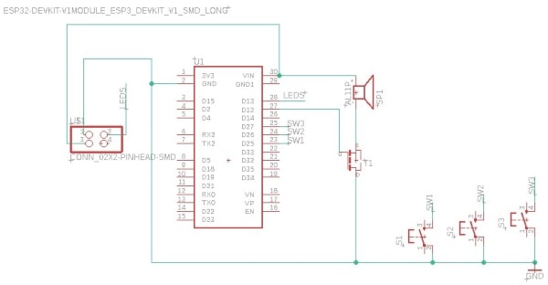
The first thing I will do is design the circuit on Eagle.
For the speaker, a high current is required which the microcontroller alone cannot provide. However, I want to control the speaker using the microcontroller. This is where a transistor comes in handy - it acts as a switch that can handle high currents. By sending a signal to the transistor’s gate from the microcontroller that means the gate will be connected to an output pin, the current can flow from the transistor’s drain to source, allowing the microcontroller to control the speaker’s operation.
Other components such as push buttons will be connected to three input pins.
The last component, the NeoPixel LED, will be connected to an output pin.
If anything is unclear about the Eagle process, such as adding components or converting it to an image, you can attend the Electronics Design and Electronics Production weeks for more information.
Here you can download my schematic design.
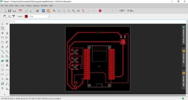
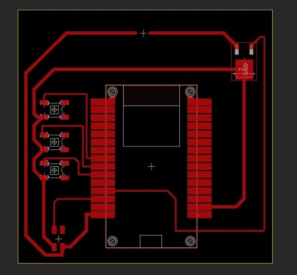
Here you can download my board design.
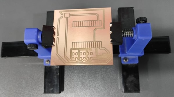
Milling and Soldering
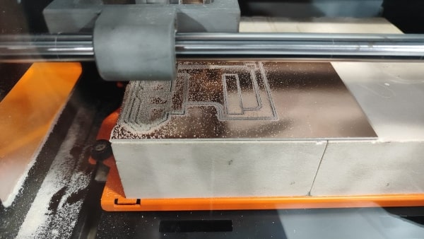
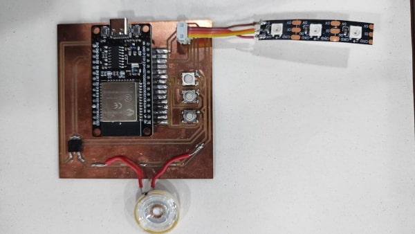
After soldering the components and uploading the code, I accidentally burned out the speaker. Initially, I thought the issue was with the code, so I continued trying different versions. Unfortunately, I burned out two more speakers before realizing that the problem was actually with the transistor, which was connected incorrectly. The error was due to the connection. I connected the drain to the ground, but it should have been connected to the source However, I didn’t have time to fix the issue at the moment, so I decided to test the speaker again in a few weeks.
Coding
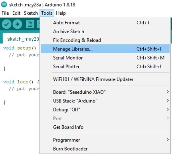
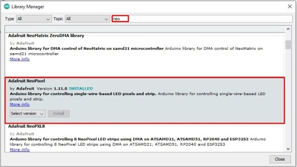
Firstly, I will include all the necessary libraries to run the NeoPixel. So we currently require understanding the process of installing a library.
Open the Arduino software and navigate to the tool menu. Select “Manage Libraries” from the dropdown. In the search box, enter the name of the library you are looking for. Locate the library in the search results click the “Install” button to proceed with the installation.
Then, I will define the pin that will connect to the NeoPixel and specify how many LEDs we will use. Additionally, I will connect three switches to their input pins.
To turn off all the pixels, we will use the function “NeoPixel.clear()”. However, this will only take effect when “pixels.show()” is called.
To set a specific color, we will call the strip number and specify the RGB value.
#include <Adafruit_NeoPixel.h>
#ifdef __AVR__
#include <avr/power.h> // Required for 16 MHz Adafruit Trinket
#endif

#define PIN_NEO_PIXEL  13  // Arduino pin that connects to NeoPixel
#define NUM_PIXELS     3  // The number of LEDs (pixels) on NeoPixel

Adafruit_NeoPixel NeoPixel(NUM_PIXELS, PIN_NEO_PIXEL, NEO_GRB + NEO_KHZ800);

int SW1= 25;
int SW2=26;
int SW3=27;
int swv1=0;
int swv2=0;
int swv3=0;


void setup() {
 NeoPixel.begin(); // INITIALIZE NeoPixel strip object (REQUIRED)

 NeoPixel.clear(); // set all pixel colors to 'off'

 pinMode (SW1, INPUT_PULLUP);
 pinMode (SW2, INPUT_PULLUP);
 pinMode (SW3, INPUT_PULLUP);


}

void loop() {
swv1= digitalRead(SW1);

if(swv1==HIGH){
 NeoPixel.clear();
 NeoPixel.show();
 }
 else {

  NeoPixel.setPixelColor(0, NeoPixel.Color(255, 0, 0));
  NeoPixel.show();
  delay (2000);

  NeoPixel.clear();
  NeoPixel.show();

  }


swv2= digitalRead(SW2);

if(swv2==HIGH){
 NeoPixel.clear();
 NeoPixel.show();
 }
 else {

  NeoPixel.setPixelColor(1, NeoPixel.Color(125, 125, 0));
  NeoPixel.show();
  delay (2000);

  NeoPixel.clear();
  NeoPixel.show();

  }
swv3= digitalRead(SW3);
if(swv3==HIGH){
 NeoPixel.clear();
 NeoPixel.show();
 }
 else {

  NeoPixel.setPixelColor(2, NeoPixel.Color(125, 80, 200));
  NeoPixel.show();
  delay (2000);

  NeoPixel.clear();
  NeoPixel.show();

  }


}
The result