Computer-Aided Design
I will be using different designing programs for 2D and 3D this week, so let’s get started.
2D Design
Vector
In the 2D design vector section, I plan to use Inkscape to create a design aimed at educating children through a toy about traditional Palestinian clothing and their embroidery techniques. We will learn how to use Inkscape while we are designing. This design will be fabricated using a laser cutter in the coming weeks.
To start with our design in Inkscape, first open a new document. You will see the interface.
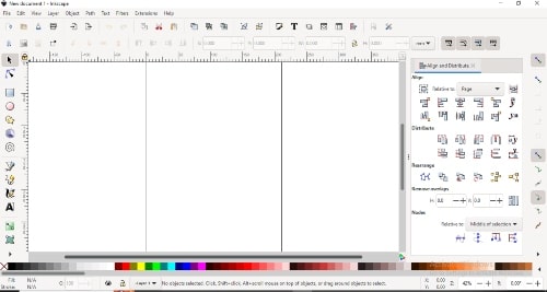
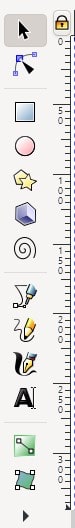
With the left side containing text, lines and shapes to draw.
At the bottom of the window, you will see the color palette.

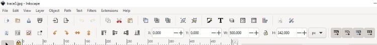
And at the top, you have the tools to control size, rotation, and location. This is a quick overview.
Now let’s start with our design.
I’ll create the outer shape in a hexagon and use an image instead of drawing it.
I will import an image in pixels which known as a raster image and perform a trace bitmap operation to convert it into a vector image.
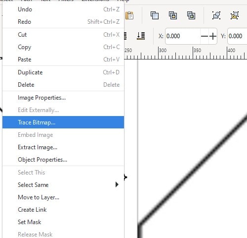
Select the photo, click on the photo or image to highlight it. With the photo selected, click the right mouse button. This action will open a context menu. In the context menu, look for the option named “Trace Bitmap”
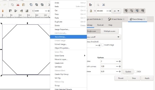
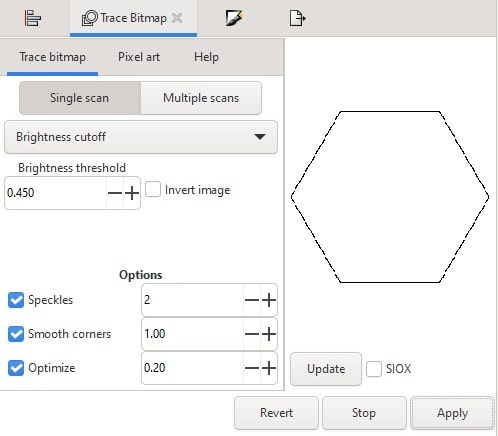
Next, we will click on the “Apply” button to generate the vector from the pixel.
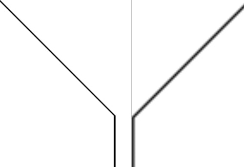
We can observe the difference between pixels and vectors.
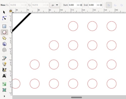
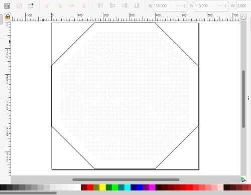
Now, I will draw circles that will be holes in the fabrication process. This will function as the base for the embroidery. It is necessary to maintain a constant distance between the circles.
The design is now finished, and here it is.
Here you can download the design.
Raster
Honestly, this is my first time using a raster program. I decided to download GIMP and work on a basic logo to familiarize myself with the basics of the program.
Here is the tutorial I followed.
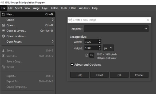
Click on the “File” menu, select “New” and choose the size of your canvas
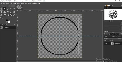
I will draw two circles on the first layer in order to obtain the region between them, creating a circular shape with thickness.
I will create a new layer and repeat the process, but this time using rectangles and rotating them 45 degrees.
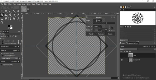
Now, I would like to remove the overlapping parts. I will add text and make some modifications to the background color.
This is the final result. By the way, this is how I write my name in Arabic.

Here you can download the design.
3D Design
In this section of my assignment this week, I seized the opportunity to create a toy for kids that explains the hydraulic system in the simplest and most interesting way possible.
I have decided to implement my model in Fusion 360, let’s begin discussing all the commands I used and how we can derive benefits from them.
Design
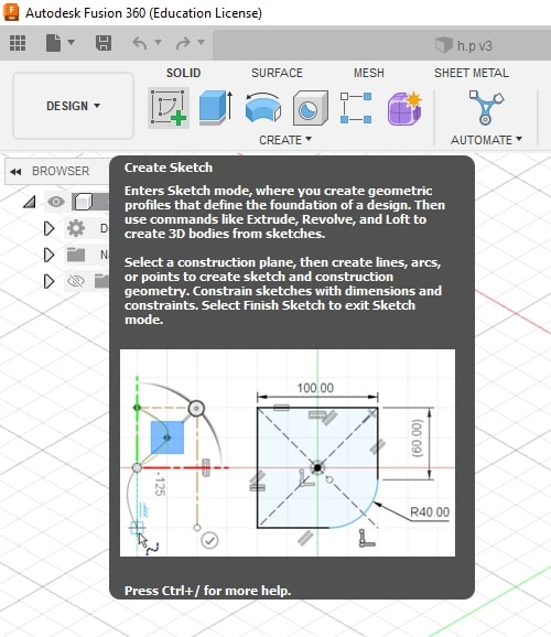
Create Sketch
Create a sketch in Autodesk Fusion 360 refers to the process of creating a 2D design. The sketch can be used as the basis for creating 3D models.
The Create Tab
The Create tab in Autodesk Fusion 360 contains basic shapes and templates that can be used as a starting point for your design.
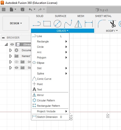
In my design, I used circles, rectangles, and lines. I also used a rectangular pattern.
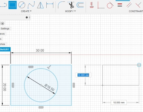
When using the circle command, you must define the center point and the radius.
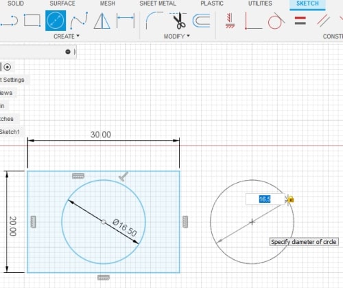
To use the rectangular command, you had to define the start point of rectangular and specify its size.
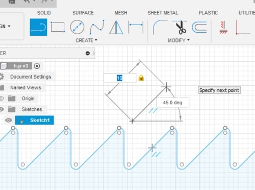
For the line command, you had to define the start point, its length, and the degree between the x-axis and it.
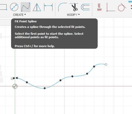
The spline command allows you to create a curved path defined by control points. To use the spline command, you have to specify the control that define the shape of the spline.
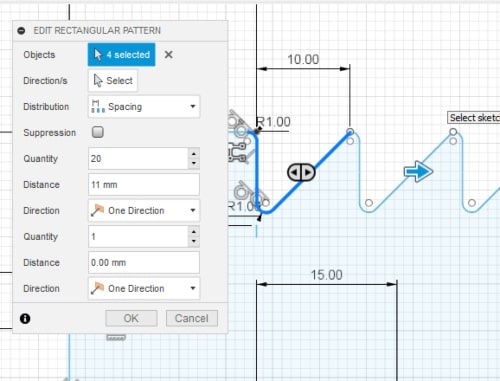
I used a rectangular pattern to create the path for the toy. The pattern allowed me to efficiently repeat a specific design element and save time compared to manual creation.
To use this command, you must specify the number of repetitions you want for the selected item and the distance between each repetition.
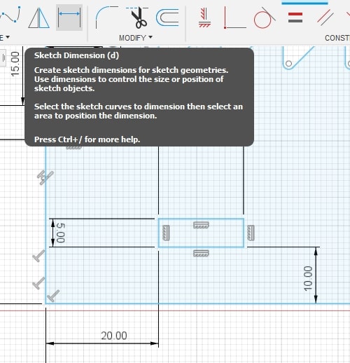
Sketch dimension is a feature used to define the size or distance between objects in a sketch.
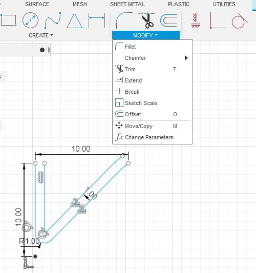
The Modify Tab
The Modify tab in fusion 360, helps you to make changes to your design, allowing you to quickly and easily make modifications as needed, rather than having to recreate your entire design from scratch.
The trim command can be used on sketches to remove unwanted lines or shapes also to cut away parts of a 3D model that you don’t need.

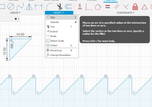
The fillet command is a useful tool for adding rounded edges to your 3D models or sketches. It allows you to blend the corners of two adjacent faces into a smooth and curved transition by defining the radius of the edge. This also improves its functionality and performance by reducing stress concentration, which is exactly what I need for my design.
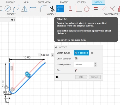
The offset command allows you to create a copy of a model that is parallel and a specified distance away from the original. To use this command, you must specify the distance and direction of the new model.
The Constrain Tab
The Constrain tab in Fusion 360, constraints are used to control the behavior and relationships between different design elements. For example, constraints can be used to fix the position of a model, control the size and shape of an object, or enforce geometric relationships between different parts of a design.
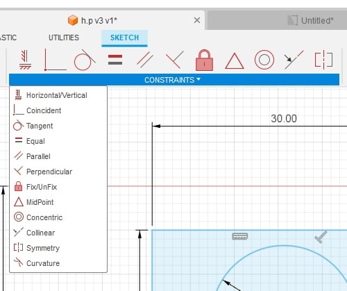
In my design I used the tangent command.
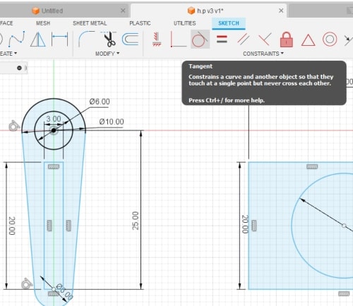
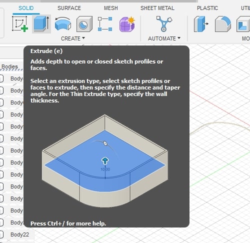
Once the sketch is completed, it’s time to move on to extruding it and putting all the pieces together.
The extrude command is used to create 3D models from 2D profiles this allows you to create solid models from a flat sketch or drawing. You can control the depth and direction of the extrusion and you can also set parameters such as draft angle, taper angle, and corner radius to shape the extruded object.
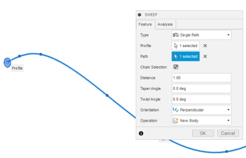
The sweep command can be used to create a 3D object by sweeping a profile along a path.
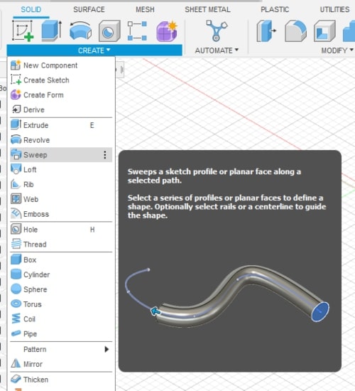
A taper angle can be applied to the sweep to create a tapered shape, where one end of the object is wider or narrower than the other.
Render
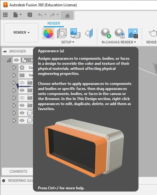
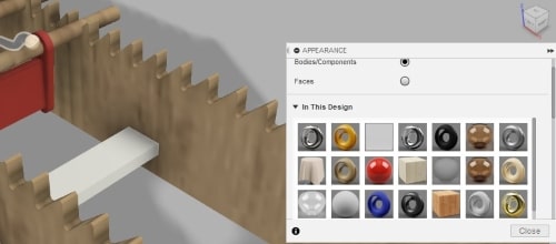
Upon completing the assembly of the model, it’s crucial to bring it to life through rendering and adding appropriate materials.
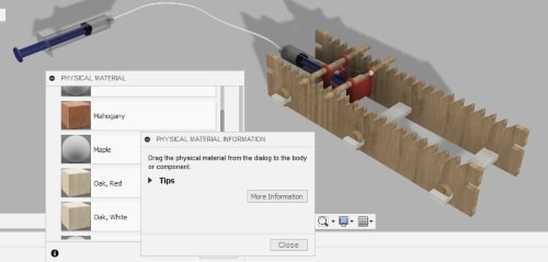
Now, as we begin the rendering process, we need to navigate to the “Appearance” section. Click on “Appearance” and a list of available materials will be displayed. From there, I will select and apply the desired material to the specific part. Drag and drop the material as simple as that.
This is the assembly in fusion 360 step by step.

And this the final result.

Here you can download the design.
Compress Images and Videos
I use a web application to resize my photos and make them the same width, and then I use another web application named Compress PNG/JPG to compress them, and for videos, I uploaded them on YouTube and attached the links.
This is an external link to befunky.com
This is an external link to compress.com