Computer Controlled Machining
Group Assignment
Prior to operating any machine, it is crucial to prioritize safety for both ourselves and the laboratory. To achieve this, we must strictly follow the provided safety instructions. The necessary safety guidelines for using the CNC machine are clearly outlined through the following signs:

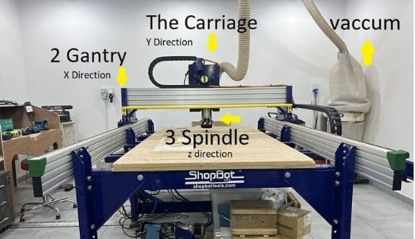
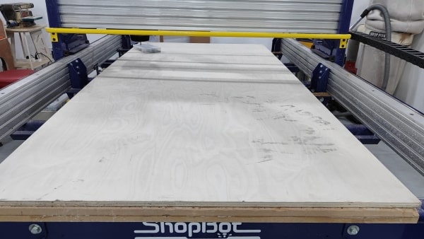
At TechWorks, we have the ShopBot PRSalpha ATC 96-60-8 CNC machine, which offers the following specifications:
-
Working Area (Length x Width x Plunge): 105” x 61” x 8” (2.67m x 1.55m x 0.2m)
-
XY Moving Speed (with full cutting force): Maximum 5” per second (7m/min)
-
Z Move Speed (with full cutting force): Maximum 2” per second (3m/min)
-
Step Resolution: 0.0004” (0.010mm)
-
Spindle RPM: Maximum 18,000 RPM
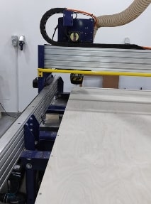
The machine is equipped with the following axes for movement:
-
X-axis: Horizontal movement along the length of the machine.
-
Y-axis: Horizontal movement across the width of the machine.
-
Z-axis: Vertical movement, controlling the depth or plunge of the cutting tool.
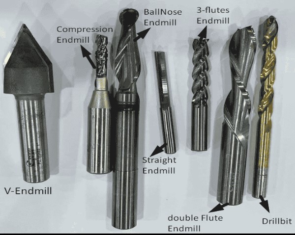
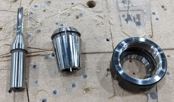
In CNC machining, a variety of tools are available, each with distinct characteristics such as size and material. These attributes determine the suitability of a particular tool for specific operations based on factors like shape, size, and material type.
At TechWorks, we employ a range of tools, but primarily distinguish between those designed solely for drilling and those suitable for milling as well. Tools exclusively for drilling lack sharp edges on their flutes, making them unsuitable for milling tasks. On the other hand, end mills can be used for both drilling and milling operations, thanks to their versatility and ability to perform both functions effectively.
Each endmill utilized in CNC machining requires specific settings, and this information is typically provided by the tool manufacturer. For instance, at TechWorks, we often use Onsrud tools, and different materials necessitate distinct cutting settings. Several crucial parameters come into play, including the number of flutes, feed rate, chip load, and RPM.
To determine the appropriate feeds and speeds, we rely on the fswizard calculator. By inputting the following settings into the calculator, we can calculate the optimal values:
-
Tool type: Whether it’s a flat endmill or a ball-nose endmill.
-
Tool diameter.
-
Tool coating (if applicable).
-
Flute angle, distinguishing between helix-shaped and flat endmills.
-
Flute length.
-
Shank diameter, which can be equal to or larger than the tool diameter.
-
Chip load, representing the thickness of material removed during cutting. This value is typically provided by the tool manufacturer.
-
RPM, denoting the rotation speed per minute. For our ShopBot machine, the maximum RPM is 18,000.
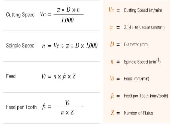
Additionally, feeds and speeds can be calculated using the following equations:
Once we completed the safety training and familiarized ourselves with the tools and the machine, we proceeded to conduct a series of tests, including the following:
-
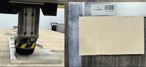
We practiced securing the wood board firmly onto the sacrifice bed using screws. This ensured stability during the cutting process.
-
After the cutting operation, we meticulously measured the alignment of the finished piece. We were pleased to find that it exhibited precise alignment with sharp 90-degree angles at the corners.
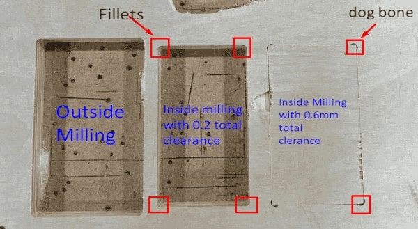
During our clearance testing, we conducted the following experiments:
For outside milling, we successfully obtained a rectangle with precise dimensions that closely matched the design specifications. The accuracy of the dimensions indicated the effectiveness of the outside milling process.
When performing inside milling with a clearance of 0.1mm, we observed that the corners exhibited fillets. These fillets were equal to the radius of the cutting tool, making it impossible to fit the rectangle obtained from the outside milling process.
In another attempt at inside milling, we adjusted the clearance to 0.6mm on each side, along with a 0.6mm height and width clearance, including the addition of dog bone features. This modification allowed us to successfully place the rectangle within the milled space, achieving a suitable clearance for the desired fit.
In conclusion, we have gathered the following key points from our CNC machining experience:
Adhering to safety instructions is paramount when operating the CNC machine. It is crucial to never leave the machine unattended while it is running to ensure the safety of both the operator and the machine.
Proper fixturing of the workpiece is essential for safe and successful cutting operations. Inadequate fixturing can lead to tool breakage, operator injuries, and machine damage. It is important to take the necessary precautions to securely hold the workpiece in place.
The running time of the machine depends on the complexity and size of the job being performed. More intricate and larger projects may require additional time for completion.
When measuring the dimensions of the cut rectangle, we observed high accuracy with an error of only 0.0(X)mm compared to the design. This demonstrates the machine’s capability to achieve precise milling results, indicating its reliability in creating accurate parts.
By considering these points and implementing proper safety measures, we can maximize the efficiency and effectiveness of CNC machining operations.
Individual Assignment
Design
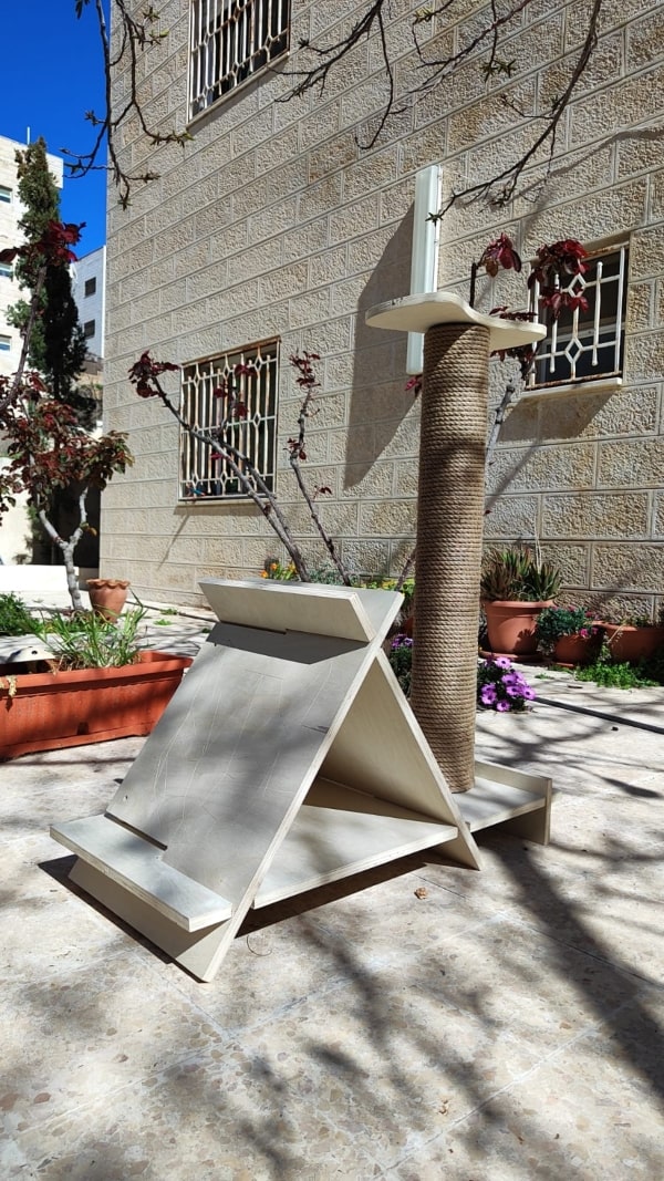
For this week’s assignment, I chose to fabricate a cat house for my cats. I started by using Fusion 360 and creating some designs. However, I was completely unsatisfied with my first design.
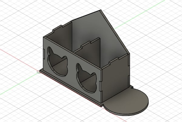
So I redesigned it and added some playing parts. I also did something different than just creating a simple box.
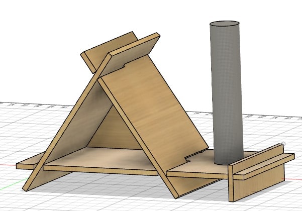
I planned for all the parts to fit together without the need for any glue or screws.
Now, I am incredibly satisfied with the final design compared to the initial one.
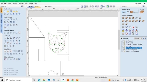
V-Carve
After finishing the design, I proceeded to use V-Carve to prepare for the fabrication process.
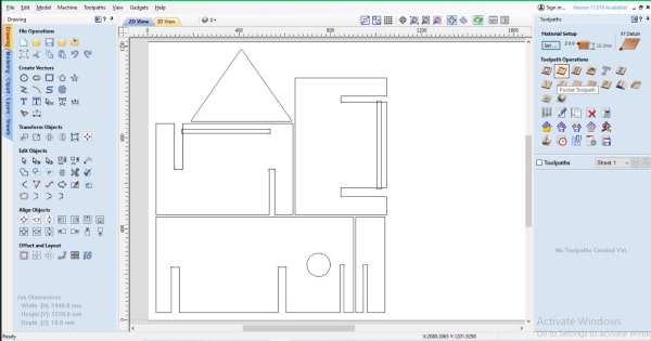
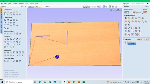
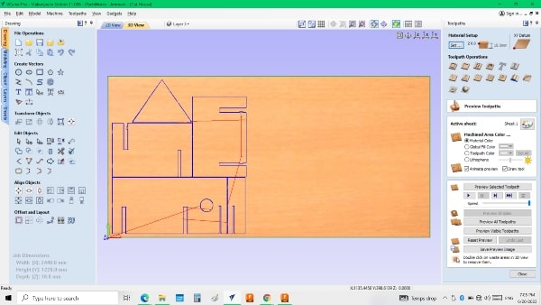
When you open V-Carve, this is the interface you will see.
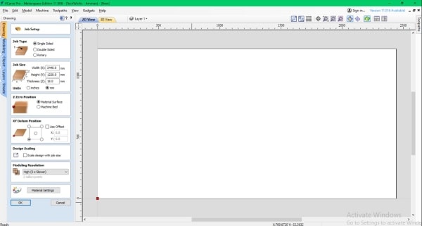
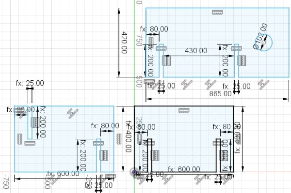
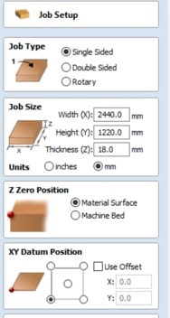
Here, we can set up the job according to the dimensions of the part that will be used
When we import the DXF file to V-Carve, it may be placed in a random position. In that case, we need to select the “Center” command to center it on the surface that we have already specified the dimensions for in the job setup.
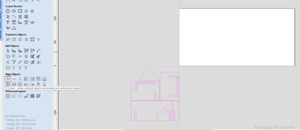
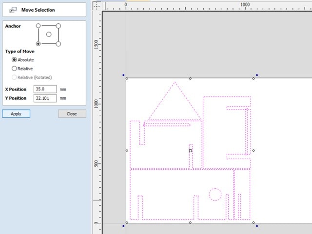
Then, I will move it to the corner of the board so that I can utilize the remaining space efficiently without wasting any of it.
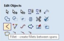
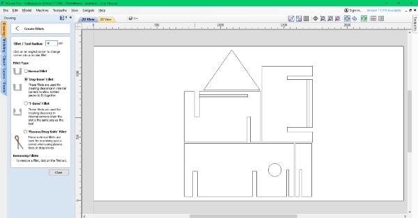
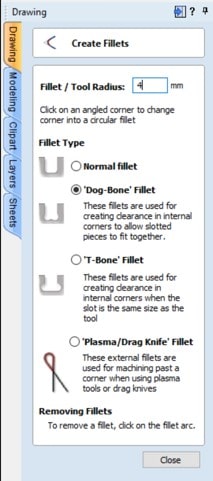
Okay, it’s important to note that the tool has a diameter, which means that if we don’t put a fillet on the sharp edges, the tool won’t be able to create sharp edges because it can’t reach the edge. As a result, the joint will be smaller, and it won’t fit properly. To avoid this, we can add an outer fillet to the edges, and we need to take into consideration the tool’s diameter when doing so.
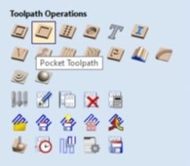
Before diving into the tool paths, it’s worth discussing the difference between pocket and profile operations.
The main difference between pocket and profile operations lies in their purpose and the way they cut into the material.
Pocket: A pocket operation involves cutting out a flat area or recessed pocket within a material. It removes material from the inside, leaving a flat or curved surface. Pockets are commonly used for creating cavities, inlays, or recesses for fitting objects.
Profile: A profile operation, on the other hand, cuts along the outline or perimeter of a shape, following a specific path. It does not remove material from the inside like a pocket. Profile cuts can be done on the outer edge of a material, inside holes, or along any desired path. Profiles are often used for cutting out shapes or creating detailed outlines.
In summary, pockets remove material from the inside to create recessed areas, while profiles cut along the outline or specific paths to shape the edges of a material.
Now, I will create a pocket on the sides of the house so the back that it will fit on the sides without any gaps.
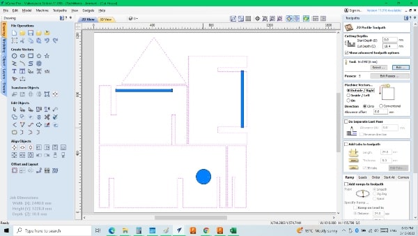
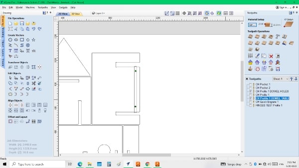
All the pockets in my design are indicated by the color blue. I created two separate toolpaths because there is a difference in the depth of each pocket.
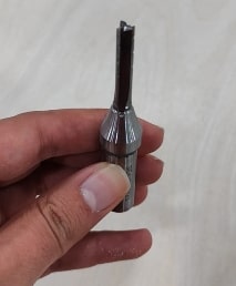
This is the tool that I will be using, so I will include its information in the “Edit Tool” section.
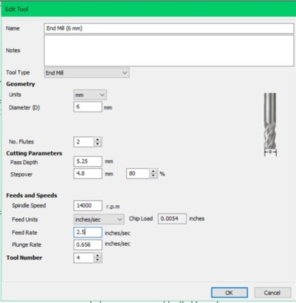
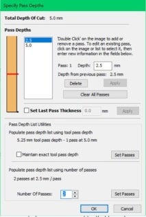
Since we can’t machine the entire depth in one pass, we’ll need to divide it into two or more passes. I’ll determine the depth step, and the program will automatically divide the full depth into equal steps.
Afterwards, I selected the cut path to shape the profile, using the same tool as before.
I had a change of plans and decided to use a circular profile to cut through the material instead of creating a pocket.
Additionally, I will create holes on the table and the piece itself. Furthermore, I will engrave a cat shape on one side of the piece so that I can later flip it over and engrave on the other side as well.
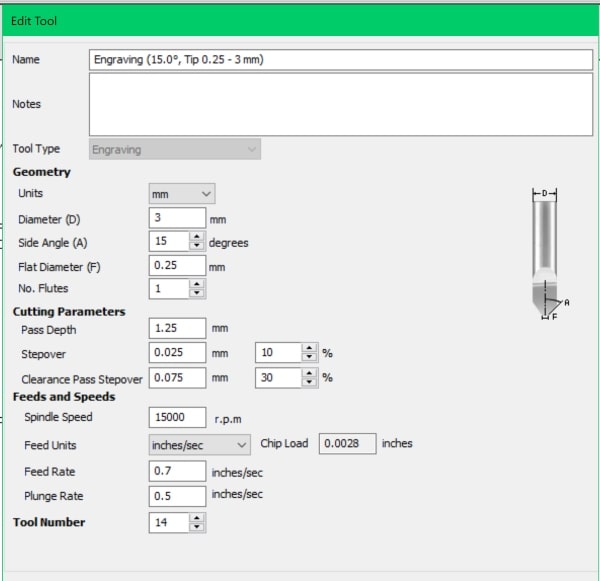
Here is the engrave tool that I will be using for the project.
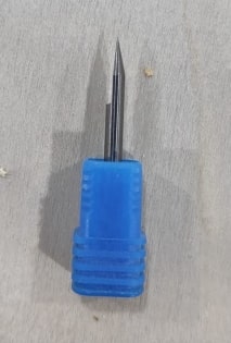
I will include all the necessary information about the engrave tool, similar to what we did for the previous tool. This will ensure that the tool is properly identified and its specifications are documented for future reference.
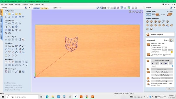
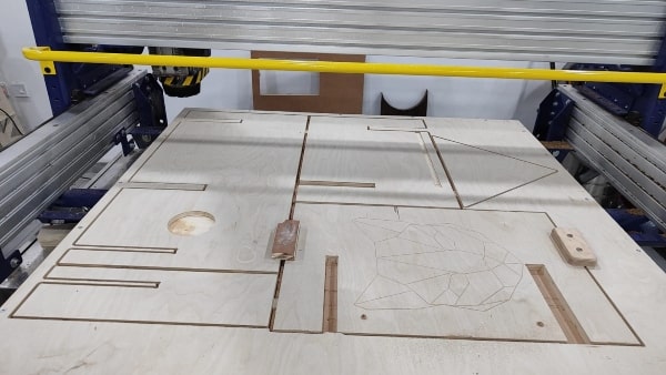
With the completion of the V-Carve process and all the necessary preparations, I am now ready to proceed to the machine and begin the fabrication or production phase.
CNC Router
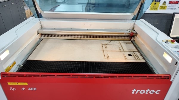
Before proceeding with the CNC machine, I created a prototype of the project using a laser cutter. This allowed me to test and refine the design, ensuring that it meets my expectations before executing it on the CNC machine.
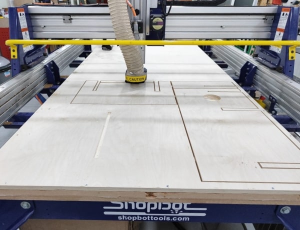
I placed the wood that I will be working with onto the bed of the machine and secured it in place using screws. This ensures that the wood remains firmly fixed during the machining process, minimizing any movement or shifting that could affect the accuracy of the cuts.
To establish a reference point for my work, I will move the machine to the edge where I intend to place it as the zero reference. This means that all operations will be based on this reference point.
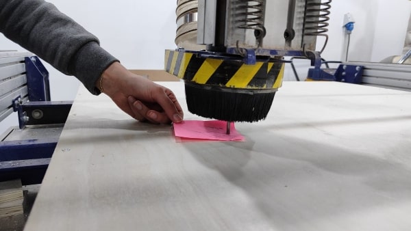
The next step is to set the tool for zeroing the Z-axis.
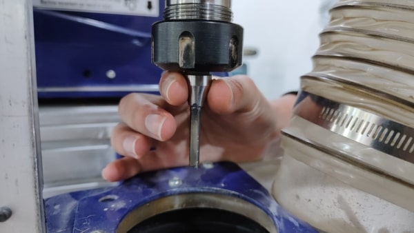
After ensuring that the tool is securely fixed in place, I will lower it using the Page Down key on the keyboard. As I approach the bed, I will press the ‘D’ key to make incremental movements, taking it step by step rather than continuous motion. Meanwhile, I will keep a sheet of paper under the tool, gradually moving it until it no longer slides easily. This indicates that the tool has reached the desired zero position. At this point, I will set the Z-axis to zero and press “D” again to raise the tool more quickly.
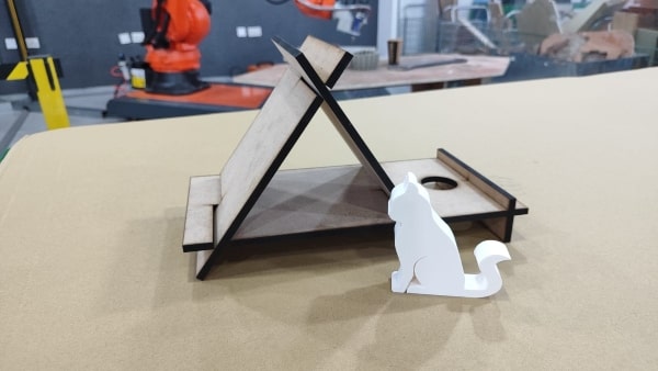
Assembling

Hero Shot