Electronics Production
Group assignment
To characterize the design rules for your in-house PCB production process, we need to run a test job using a 1/64 tool to determine the thickness of the traces we can create, and a 1/32 tool to cut the test. Just so you know, we’re using a Roland SRM-20.
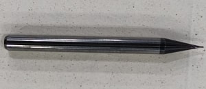
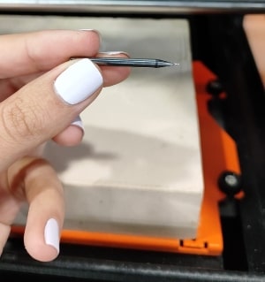
The tracing tool 1/64 mm.
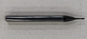
The cutting tool 1/32 mm.
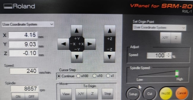
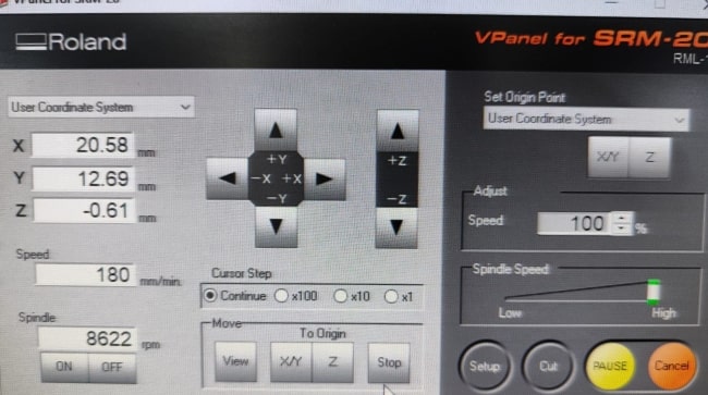
We ran the trace job at a speed (the head speed) of 240mm/min, while for the cut job it was 180mm/min. The spindle (the tool speed) was positioned very close to the material in both the cut and trace jobs, with an average speed of about 8600rpm.
Tracing:
Cutting:
The result:
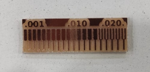
In conclusion, when using the milling tool with a 1/64 bit, I have found that I can achieve good tracing starting from a thickness of 0.01 inch. However, to ensure safety and avoid accidental removal, I will make the trace lines for any input/output signal 0.04mm, which is approximately 0.015748 inch. Additionally, for traces carrying higher currents such as ground and Vcc, I will make them thicker at 0.1mm, approximately 0.039 inch.
Now we will go to the my assignment.
When we want to create a printed circuit board (PCB), there are typically three main steps involved. First, we use Eagle software to design the circuit and export the circuit to PNG. Then, we create the file that will go to the machine. Finally, we use a PCB milling or manufacturing machine to produce the actual board.
Eagle
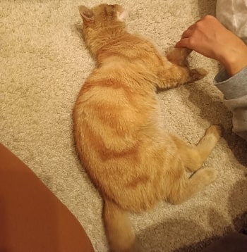
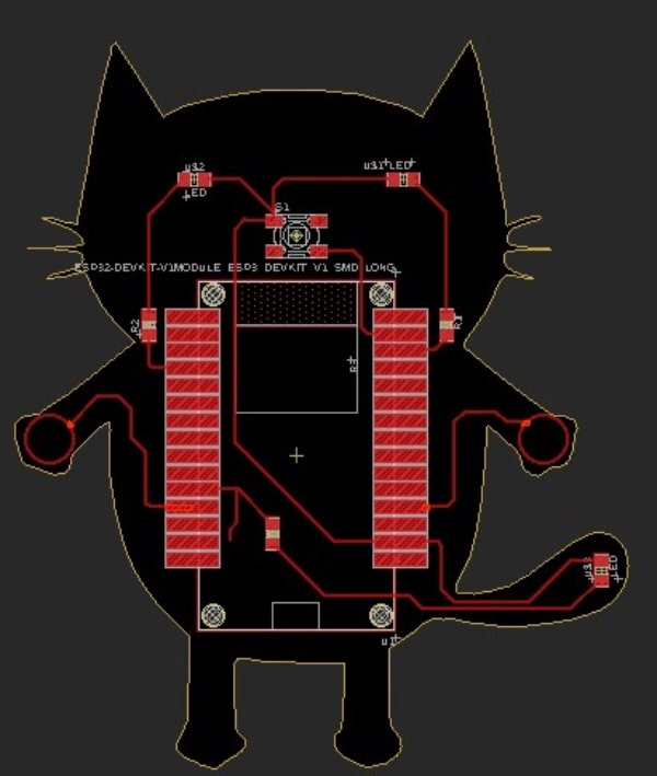
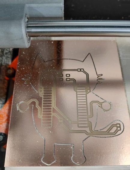
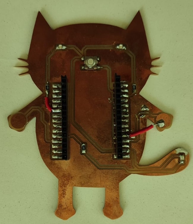
The circuit for today is inspired by Zuzi, my cat. When you touch a cat’s paw, its tail will shine, and your heart will be overwhelmed with love.
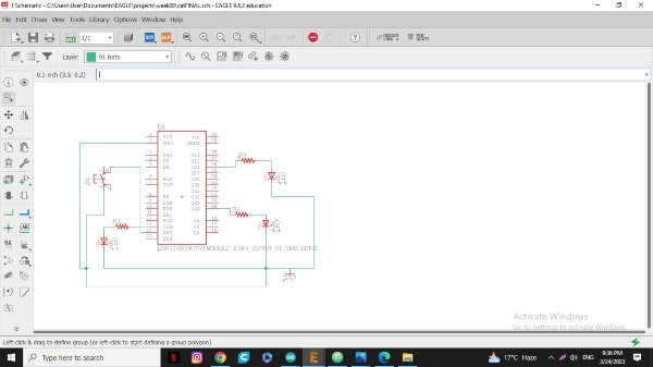
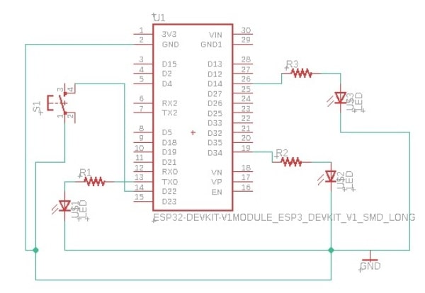
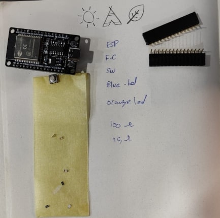
So, I started designing my board, with the ESP32 Development board “ESP WROOM32 WIFI + BLE Module” and it has a pins can behave as a touch sensor.
Capacitive sensing technology works by measuring the change in capacitance, the ability of a system to store an electric charge.
In my case, I will connect the copper on the hands to two different touch pins, and the other terminal of the capacitor will be the finger. When you change the distance between the copper and your finger, the capacitance will change. Then, the LED on the tail will light up.
And to make the cat more realistic, I will put LEDs to represent the eyes and a push button to control them.
You can find the datasheet for the blue and orange LEDs I used, so you can calculate the resistor you’ll need to use with them. Additionally, you can find the datasheet for the switch I used.
In the image below, I’ll demonstrate how to calculate the resistance needed using Ohm’s law. If you don’t have the exact value of the resistance, it’s recommended to use a larger value. For instance, I don’t have a 65 ohm resistor available for the orange led, so I’ll use a 100 ohm resistor instead. For the blue led I have 25 ohm so I will use it.

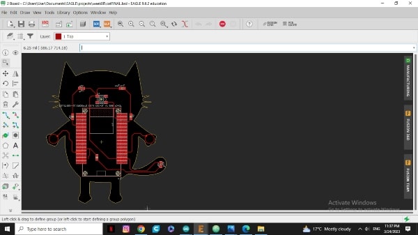
After finishing the design process in Eagle (check week 4), there are several additional steps we need to take in order to obtain the desired printed circuit board. These steps include optimizing the circuit layout.
When creating the layout for your printed circuit board, it’s important to include an outer border around the edges of the board create it on unused layer. This border increases the width of the cutting path and helps to ensure that the board is properly cut during the manufacturing process. We recommend a minimum spacing of 8mm between shapes, which corresponds to the diameter of the milling tool that we use to create the board.
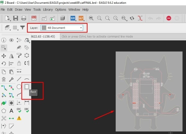
There is another option you can use in addition to drawing an outer border. You can adjust the width of the yellow box that appears around the perimeter of the board using the “info” command. By setting the width of the yellow box to 8mm.
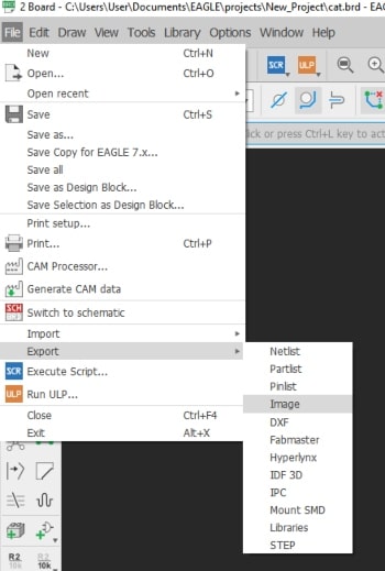
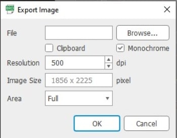
After that we need to export the circuit board to PNG so the website www.modsproject.org, is able to accept it.
To produce the necessary files for PCB fabrication, we typically use two different tools with different diameters. The first tool is used for tracing, while the second tool is used for cutting. As a result, we will generate two separate PNG files: one for the tracing tool, which will contain all of the traces for the board, and another for the cutting tool, which will contain all of the necessary information for cutting the board to its final shape.
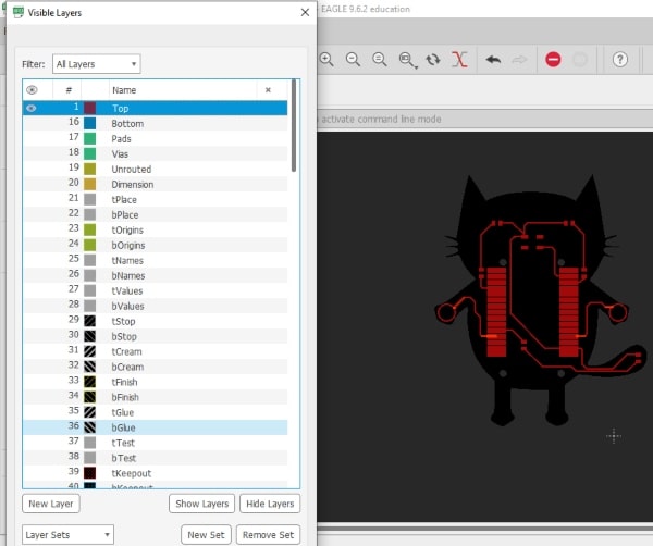
Prior to exporting the printed circuit board design as PNG files, we will need to adjust the layer settings in our PCB design software. This involves hiding any layers that are not required for the specific PNG export. For instance, we will hide any layers that are not related to tracing for the trace PNG file, and similarly for the cutting PNG file. Additionally, it is important to note that even if a layer is hidden, it will still contribute to the overall dimensions of the design. Therefore, when exporting the PNG files, the dimensions will be based on the outermost dimensions of the design. Repeat all these steps for the dimension layer.
In PCB manufacturing, the printed circuit board design is typically represented as a black and white image in a PNG format. During the manufacturing process, any black areas in the PNG image are where the copper will be removed from the board. And, any white areas in the PNG image are where the copper will remain.
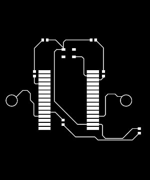
I will now make some edits to the PNG I received from Eagle to ensure that all the spaces I want to keep are white.
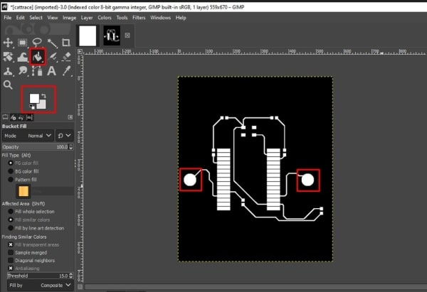
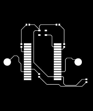
This is the PNG for tracing level.
For the cutting level, I want to keep all things and just cut the outer line.G


Modsproject
Let’s go to www.modsproject.org to get the file ready for the machine.
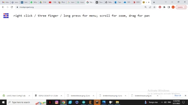
When you visit the ModsProject website, the main page or first page will be displayed. To continue, you will need to right-click on the page.
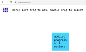
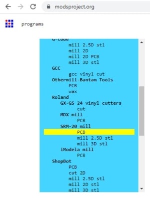
Choose “programs”.
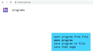
Then “open program”.
Here we will choose the machine, in my case, Roland SRM-20.
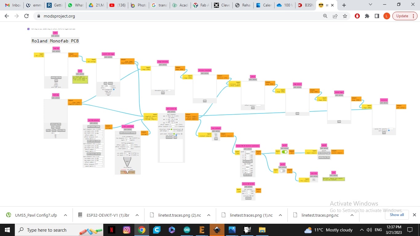
After that, this page will appear, featuring various boxes where you can input the appropriate settings for cutting and tracing.
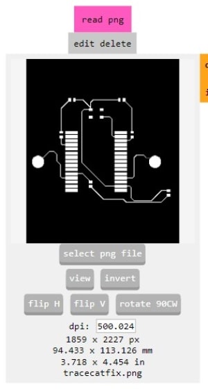
From this block, you can insert the PNG file that you want to cut or trace. Also, it will display the dimensions of the photo for you.
Here, we have selected the milling tool. We will be using a 1/64 inch tool for tracing and a 1/32 inch tool for outlining.
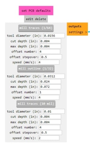
Also, you have the option to determine both the offset numbers and offset stepover.
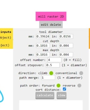
To optimize speed, we recommend two different settings: one for tracing at a speed of 4, and another for cutting at a speed of 3. The origin has to be zero.
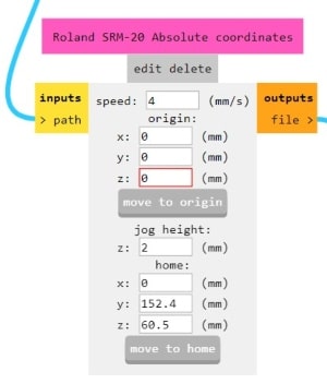
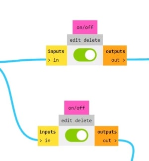
Make sure you enable these buttons so that the RML file can be downloaded.
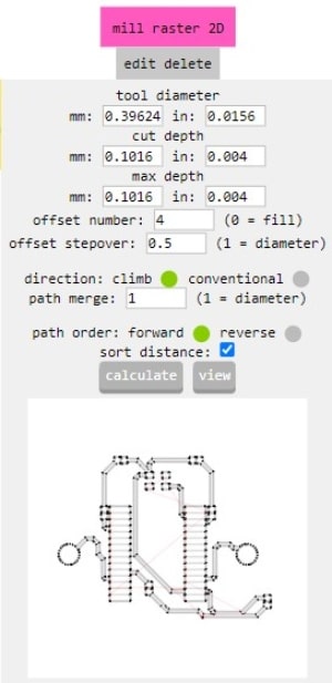
After completing all the steps, press calculate to generate the RML file.
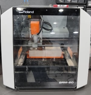
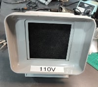
Roland SRM-20
This is the Roland SRM-20 machine that I will be using in the lab for milling my PCBs.
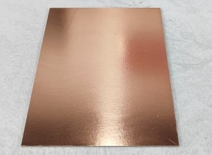
I will use a double layer fiber board to mill my circuit on it, even though my circuit is only one layer. But this is what we found in the lab.
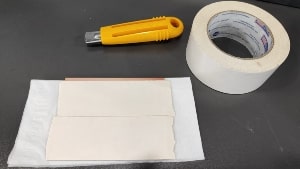
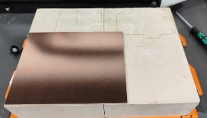
In order to attach it to the bed of the machine, I require a double-sided adhesive. Afterwards, I will use my hand to press it down and ensure there are no air bubbles and it is almost level.

Now I need to learn how to change the tool. I will start by putting the tracing tool first, the 1/64 inch.

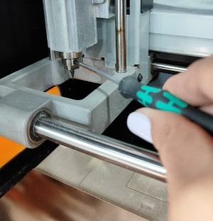
After changing my tool, I need to reset the zero point of my work.
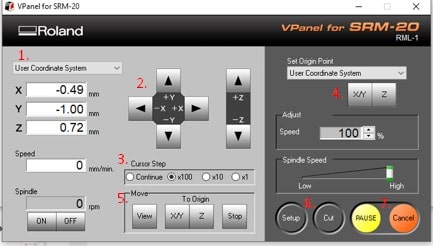
But first let’s become more familiar with the VPanel program.
-
Select the user coordinate system or the machine coordinate system so that all points below will be relative to the system you choose.
-
This arrow is used to control the milling head on all axes.
-
The steps here indicate how many millimeters the head will move in one step. When we set it to 100, it means that the head will move 1 millimeter per step. Also, please note that it is recommended not to use the continuous mode when moving the Z-axis to avoid damaging the tool.
-
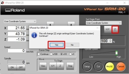
When we reach the point that we want to set as the zero reference, we press it.
-
Here, selecting the machine coordinate system will move the head to the absolute zero of the machine, while selecting the user coordinate system will move the head to your zero point.
-
The “Cut” button is used to upload the job.
-
Keep your mouse hovering over the “Pause” and “Cancel” buttons so that you can press them immediately if anything happens, especially at the beginning of the job.
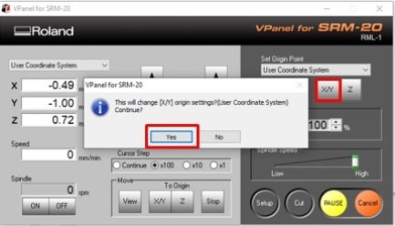
Once you have positioned the head where you want it on the XY axis, press the “X/Y” button to establish it as the a zero point, after setting the zero point, the bottom left corner of the job will serve as the starting point.
To set the Z-axis to zero, you need to adjust the steps to 0.1mm and take the zero point at the center of your job’s working area. Once you’ve done this, you’ll need to manually lower the tool a few millimeters until it touches the bed.

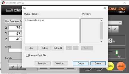
Next, press “Cut”, add the file, and then press “Output” to start the job.
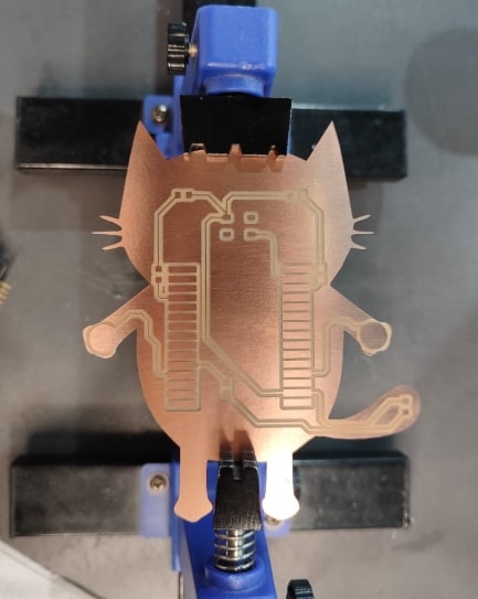
Here is the result after tracing.
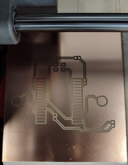
After milling the trace, we need to change to a 1/32 inch cutting tool and repeat the Z-axis calibration.

Soldring
I have prepared all the components to begin soldering.
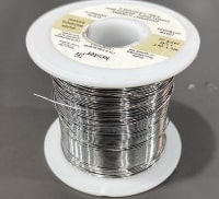
Solder wire is a thin wire made of a metal alloy that is used in the process of soldering.
The soldering iron is used to heat the joint being soldered, while the solder wire is melted by the heat.
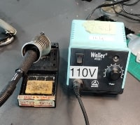
It’s important to note that soldering itself can produce harmful fumes and particles, to protect yourself from the potential health hazards of soldering, it’s important to work in a well-ventilated area this equipment will help on that.
When I started coding the circuit, I realized that I had mistakenly used two pins that were not suitable for the purpose. I had overlooked checking whether they were input or output pins. So, I had to cut their traces using a scalpel and solder a jumper wire to connect them to the correct pins. In the future, I would recommend using a website that can help you check whether the pins are suitable for input or output before beginning the design process on the link below.
https://randomnerdtutorials.com/esp32-pinout-reference-gpios/
The correct pin for the left eye is 32 and 12 for the right hand.
Coding
I programmed my circuit so that when I push the button, which is located where the nose would be, the LEDs (acting as eyes) will turn off. Otherwise, they will remain lit. Additionally, when I touch or get closer to the hands, the LED on the tail will shine. The hands are touch sensors that behave like the terminals of a capacitor.
The code:
int switch_sensor = 22;
int digital_sensor_value = 0;
int led_eye_right = 1;
int led_eye_left = 32;

int led_tail = 14;

int right_hand = 12;
int left_hand = 4;

const int threshold = 80;

int touchValueR = 0;
int touchValueL = 0;


void setup() {

  pinMode(switch_sensor, INPUT_PULLUP);
  pinMode(led_eye_right, OUTPUT);
  pinMode(led_eye_left, OUTPUT);
  pinMode(led_tail, OUTPUT);

}


void loop() {

  digital_sensor_value = digitalRead(switch_sensor);
  digitalWrite(led_eye_right, digital_sensor_value);
  digitalWrite(led_eye_left, digital_sensor_value);

delay(500);

 touchValueR = touchRead(right_hand);
 touchValueL = touchRead(left_hand);

 if(touchValueR < threshold){

    digitalWrite(led_tail, HIGH);

  }
  else{

    digitalWrite(led_tail, LOW);

  }

delay(500);

   if(touchValueL < threshold){

    digitalWrite(led_tail, HIGH);

  }
  else{

    digitalWrite(led_tail, LOW);

  }

delay(500);
}
To begin with, I define all the pins that I will be using in my code. Then, I define the variables that will store the readings from these pins and initialize them to a value of zero to start with. Next, I specify which pins are input and which are output. Then I will compare the readings from the capacitive sensor with a pre-defined threshold value. The threshold value is the reading that the capacitive sensor takes when it is not being touched or affected by any other capacitors nearby. When the sensor is touched or affected by other capacitors, the readings will go down and trigger the conditional statement that I have set up.
Result

The files
Here you can download EAGLE schematic.
Here you can download EAGLE board.