Computer Controlled Cutting
Laser Cutter
Group Assignment
For the group assignment, we will characterize the speed, power, and kerf of our laser cutter on different materials.
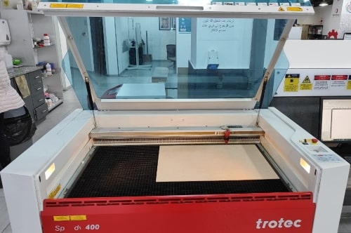
We have to mention some things before we start: The name of our machine is Trotec Speedy 400 Co2 laser engraving machine. The power we’re using is a percentage of the maximum power. In our case, the maximum power is 120 watts.
We have selected MDF with a thickness of 4.3 mm and acrylic with a thickness of 5 mm as the materials to test for optimal cutting and engraving speed and power.
We designed a test in Inkscape to test different powers and speeds.
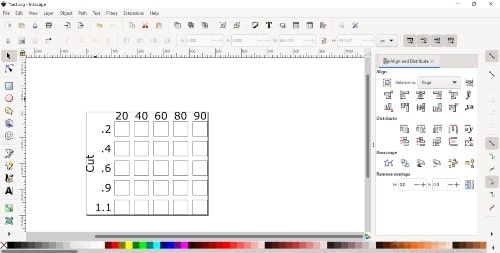
There are 16 colors that the Trotec program can understand. Each color has a speed and power setting, so we will test the first 16 settings, then edit the file and print the remaining settings
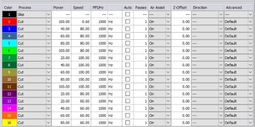
After the test, we can choose the best settings for cutting and engraving.
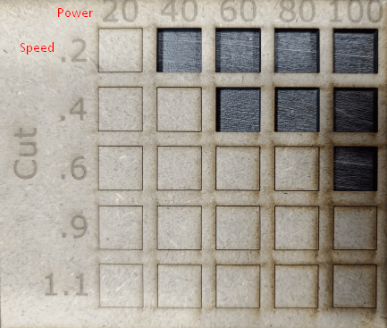
For the initial test, we cut MDF with a thickness of 4.3 mm. I maintained a constant power while adjusting the cutting speed.
In my opinion, the optimal setting is 0.4 m/sec for speed and 60% for power.
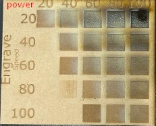
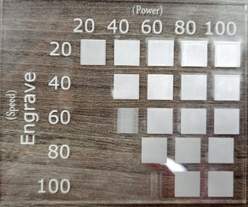
Now I will test the engrave settings. In my opinion, there is no best engrave setting because it depends on the design and function I require the engrave to serve.
Then I repeat the test with the 3mm acrylic.
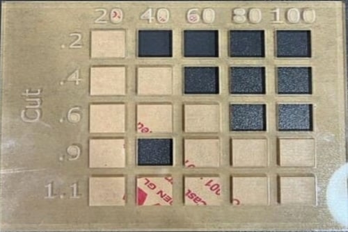
When I repeated the test, something that didn’t make sense happened. The square with a power of 40% and a speed of .9 m/sec cut through, while the same speed with a higher power didn’t cut. So, I repeated the test to realize that I did something wrong the first time.
I’ve decided to select the setting of 80% power and 0.6 m/sec speed as the optimal configuration.
To measure the kerf, we will first draw a rectangle that is 10 cm wide. Next, we will divide this rectangle into 10 smaller rectangular sections, each 1 cm in width. We will then cut this rectangle and re-measure it, noting any differences in width. Finally, we will divide the difference by number of vertical lines and this will give us the kerf measurement.
The kerf of MDF 3 mm is 0.055 mm.
The kerf of acrylic 3 mm is 0.114 mm.
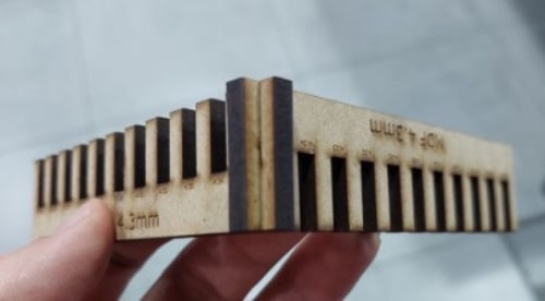
For the final test, we will be attempting the joint I tested on MDF with a thickness of 4.3 mm. During the test, the optimal joint width was found to be 4.35 mm.
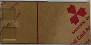
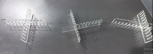
For acrylic, we initially attempted to cut with a range of 2.95-3.05 mm, but this proved unsuccessful as the joints were too loose. This was due to the kerf value for MDF being smaller than that of acrylic. For our second test, we tried a range of 2.8-2.9 mm which was successful, however, we encountered an issue when we removed the acrylic sticker as the joint became slightly loose. To address this, we conducted a final test with a range of 2.7-2.8 mm. After analyzing the results, we found that the optimal joint thickness value for acrylic was 2.74mm. This is demonstrated from right to left in the following image:
My Assignment
For my assignment this week, I have been tasked with designing a parametric construction kit. I have decided to use Fusion 360 as the platform for my project.
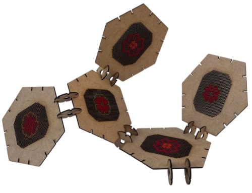
For my parametric construction kit project, I will start by designing two basic shapes a hexagonal shape and a circular shape. These shapes will have joints, which will make it easy to connect them to form various structures. Additionally, the hexagonal and circular shapes are modular, providing versatility and allowing for an unlimited number of building possibilities. This is what makes the parametric construction kit truly unique.
Let’s begin with defining parametric design. Parametric design is a way of making designs using computer algorithms and adjustable variables. This allows designers to easily change and control their designs.
I created my design using the parametric design method. By using it, I have the advantage of being able to easily adjust the thickness and the kerf if I decide to change the material I am using.
I have selected MDF with a thickness of 2.4mm for the project. I have tested this material and the kerf is 0.1, I will attach the test results below.
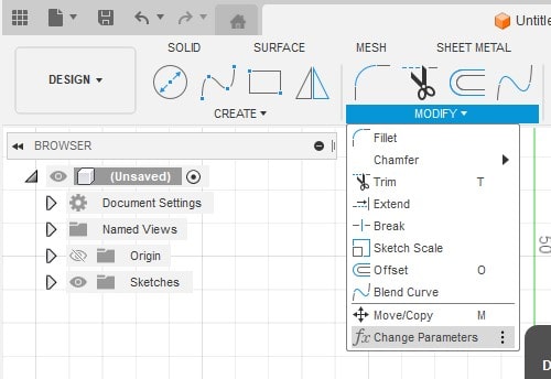
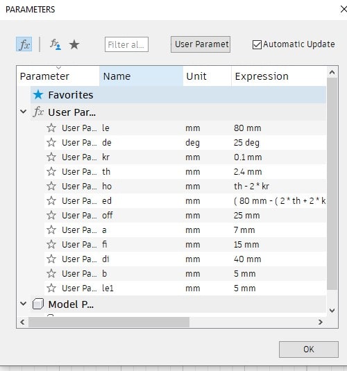
To go to the parameter options after starting a sketch, click on the “Modify” menu then select “Change Parameters” option.
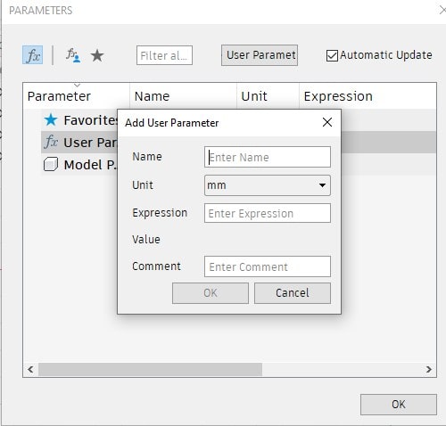
Here, we can input the name of the parameter and its corresponding value.
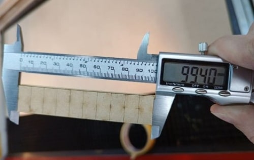
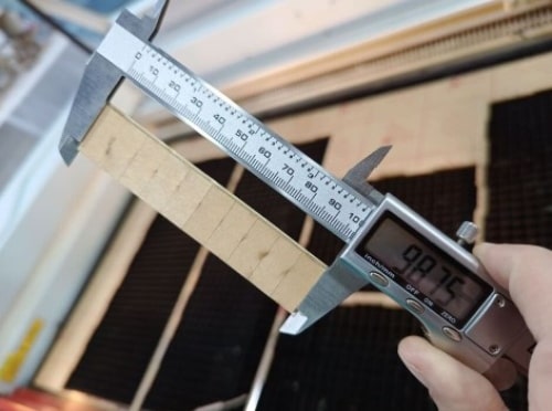
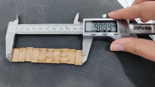
“I need to calculate the kerf for the MDF material that I will be using in my assignment, which has a thickness of 2.4mm. To do this, I will follow the same steps we used in the group assignment. The total length of the triangle is 100mm. After cutting, the length is 98.89mm. To find the kerf, I subtract 98.89 from 100, which gives me 1.11mm. Then, I divide 1.11 by 11 to get a result of 0.1009mm.
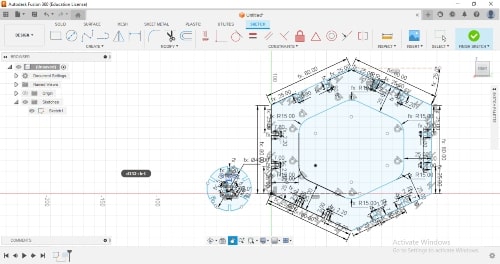
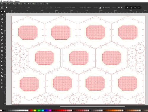
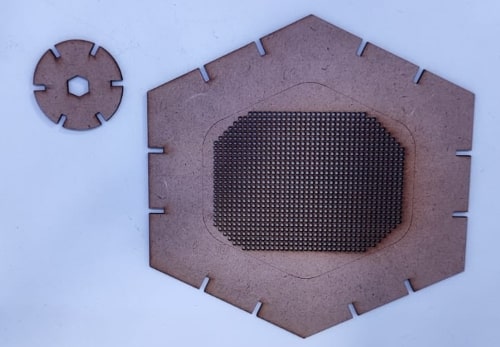
Here is the initial design that I have created, all the dimensions used in this design are parametric, which means that I can easily modify any of them.
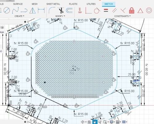
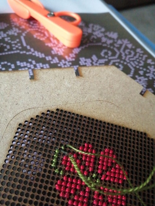
Then I realized that cutting the design in this manner would result in the material in the middle becoming waste. So, I decided to merge the 2D vector design I made last week with the current design so that we can add some embroidery to it and make it more appealing.
Once I have finished the design and saved the sketch as a DXF file, I will proceed with the fabrication using a laser cutter.
Before proceeding with the laser cutting, it is necessary to prepare the file so that the machine can accurately understand the design, you can consider it as a bridge or a link between the design phase and the laser cutting phase.
In order to prepare the file for laser cutting, I will use Inkscape software.
So we need to set the stroke line width and choose a color that your machine will be able to recognize.
The stroke width -line width- is set to 1 pixel.
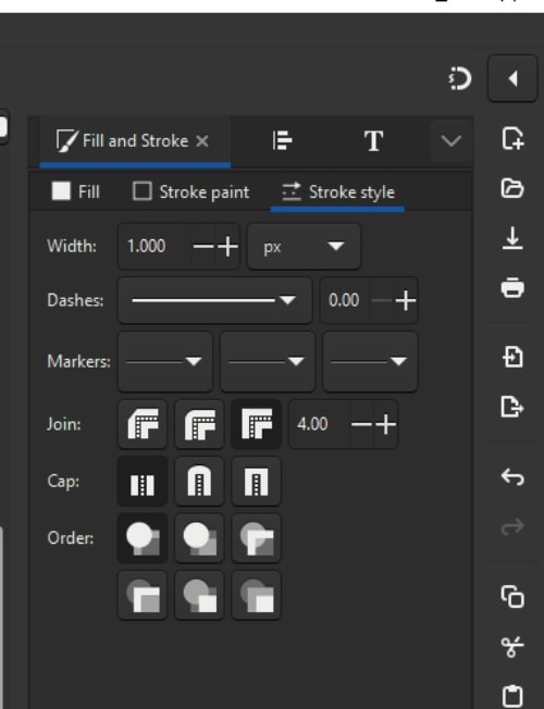
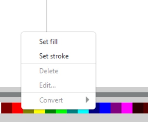
To change the color, right-click on the desired color and select Set Stroke.
To make the page around the job, press “Ctrl+Shift+R”.
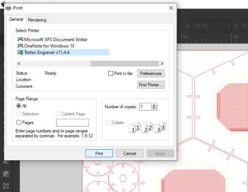
Our Trotec machine program is ready to receive the file once we have completed the preparation process. To send the file, press “Ctrl+P”.
Let’s now go to the Trotec program and start getting familiar with it.
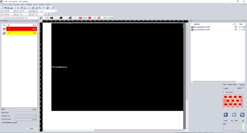
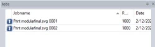
The first section is the “Jobs” section, where you will find the job you sent. Simply drag and drop the job into the workspace.
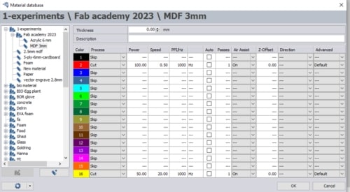
To access the material settings, double-click in the white area in the workspace and the material settings will show up.
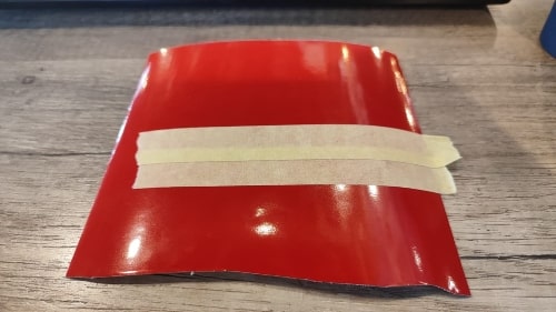
I selected the red color for cutting and the yellow color for marking. You can observe the difference in speed and power - the red color is slower but with a higher cutting power.
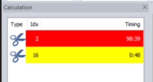
The final part we will discuss is the “Time” section, where the machine will calculate the time required to complete the job before we start.
Finally, we are in the practical section!!!
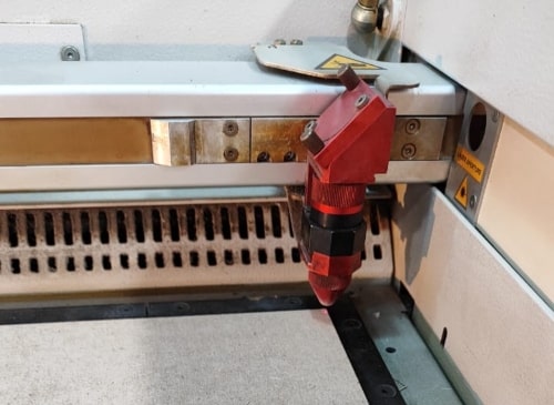
The first step is to place the board that you want to cut or engrave onto the bed of the machine. The board should be securely placed on the bed of the machine this ensures that the board will remain in the correct position and orientation during the operation, which is necessary for achieving accurate and consistent results.
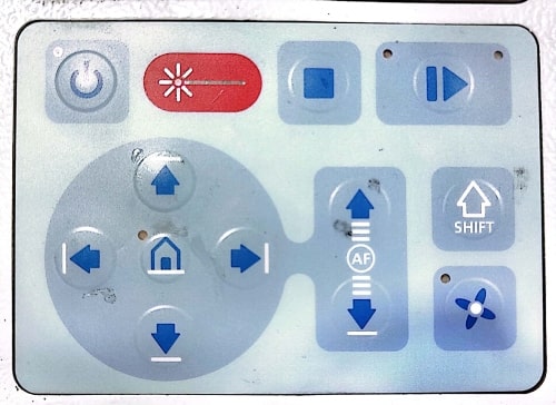
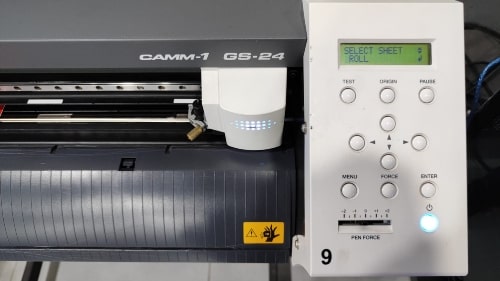
The control panel on the laser has four arrows for controlling the head in the XY axis, and the two arrows on the left are for controlling the bed.
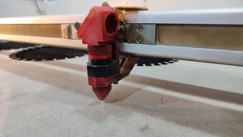
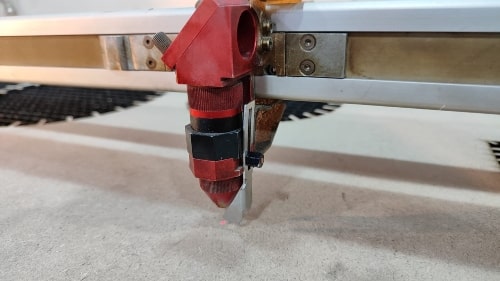
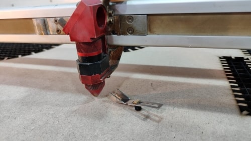
We need to focus on the distance between the laser head and the board now. We will place this metal part on the bed and raise it until the part falls down.
Using the controls on the laser, position it at the job’s starting point, and then press ‘ready’ on the computer.
The laser will start cutting and perform the job.
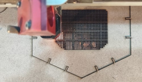
Now, let’s create some designs and add embroidery to it.
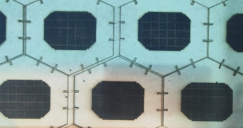
Here it is, the final result!
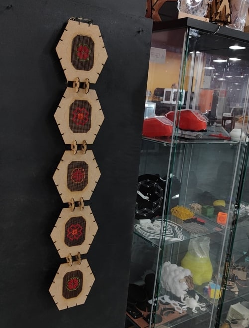
Here you can download my modular design.
Vinyl Cutter
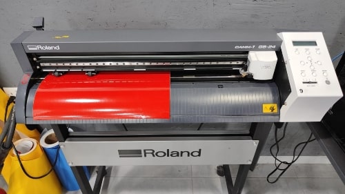
Now, for the vinyl cutter assignment, we will be using the Roland CAMM-1 GS-24.
If you want to create a sticker from the photo using a vinyl cutter, you will cut the outline of the photo. This can be done by importing the photo into the vinyl cutter program In our case, Cut Studio, creating a vector outline around the desired shape, and then sending the file to the cutter to be cut out.
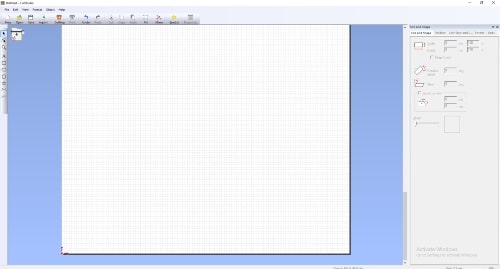
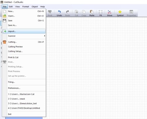
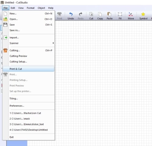
To import a photo, press the “File” menu and select “Import” then choose the desired photo.
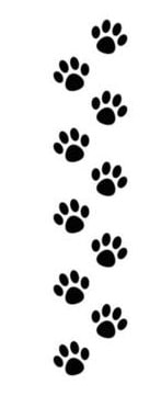
Here is the photo I will use.
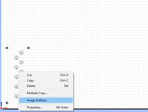
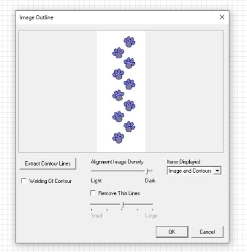
After importing the photo, right-click on it and choose “Image Outline” then select ‘Extract Contour Lines’.
Now the file is ready to be cut. To send the file to the cutter, go to the “File” menu and select “Print and Cut”.
Now let’s go to the machine to get familiar with it.
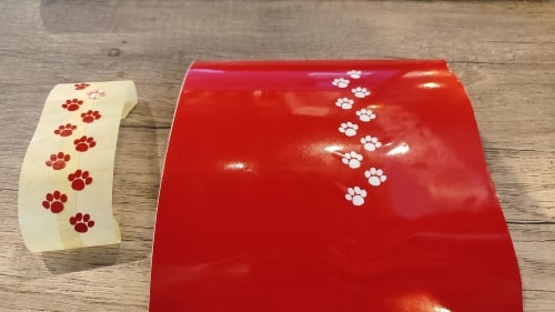
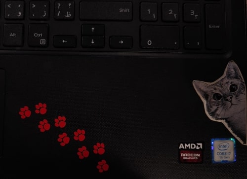
I want to put the vinyl sticker that I cut on my laptop, so I will use masking tape to preserve its shape. If I were to transfer the sticker using the original process, I would need to add an extra step of removing the uncut sticker. Since my sticker is small, I need to be very careful during this process. Instead, I can put sketch tape on the sticker to remove it and place it directly where I want. By doing so, I can skip the first step and go directly to the second.