Embedded Networking and Communications
Group Assignment
In fab academy’s Networking and Communications Week, our group embarked on a project to explore different methods of connecting two microcontrollers. Our main goal was to establish a wireless communication link between the microcontrollers and utilize it for controlling an LED lighting system. In this documentation, we will focus on our investigation of ESP-NOW, a communication protocol developed by Espressif Systems. We will demonstrate the successful implementation of ESP-NOW in our project.
ESP-NOW is a specialized communication protocol designed for low-power devices, specifically developed by Espressif Systems, the creators of ESP32 microcontrollers. It enables direct communication between devices without relying on a Wi-Fi network or access point. ESP-NOW operates in two modes: Station (STA) and Soft Access Point (AP).
Hardware Setup: We connected a push button and an LED to an ESP32 Dev Kit microcontroller. The push button served as an input for triggering the LED lighting control. Additionally, we utilized another microcontroller as the receiver, connected to a NeoPixel LED.
Configuring ESP-NOW: One ESP32 module was set up as the sender, while the other module acted as the receiver. The sender module was configured to send messages via ESP-NOW when the push button was pressed, and the receiver module was prepared to receive and interpret these messages.
Establishing Communication: The sender module, operating in STA mode, established a direct connection with the receiver module, which operated in AP mode. This direct connection facilitated peer-to-peer communication between the two microcontrollers.
LED Lighting Control: Whenever the push button was pressed on the sender module, it sent a message via ESP-NOW to the receiver module. The receiver module interpreted the message and controlled the connected LED accordingly, resulting in the desired lighting effect.
To configure the remote and receiver, we needed to determine the MAC number, which serves as a unique identifier for each MCU.
Remote code:
#include "WiFi.h"

void setup(){
  Serial.begin(115200);
  WiFi.mode(WIFI_MODE_STA);
  Serial.println(WiFi.macAddress());
}

void loop(){

}
#include

#include

uint8_t remoteMac[] = {0xB8, 0xD6, 0x1A, 0x47, 0x9A, 0x64};

const int buttonPin = 12; // GPIO 5

void setup() {
    Serial.begin(115200);

    pinMode(buttonPin, INPUT_PULLUP);

    WiFi.mode(WIFI_STA);
    WiFi.disconnect();

    if (esp_now_init() != ESP_OK) {

    Serial.println("Error initializing ESP-NOW");
    return;}

    esp_now_peer_info_t peerInfo;

    memcpy(peerInfo.peer_addr, remoteMac, 6);

    peerInfo.channel = 0;

    peerInfo.encrypt = false;

    if (esp_now_add_peer(&peerInfo) != ESP_OK) {

    Serial.println("Failed to add peer");

    return;}
    }

void loop() {
  if (digitalRead(buttonPin) == HIGH) {

  uint8_t dataToSend = 1;

  Serial.print("Data Sent: ");

  Serial.println(dataToSend);

  esp_err_t result = esp_now_send(remoteMac, &dataToSend, sizeof(dataToSend));


 if (result == ESP_OK) {

 Serial.println("Data sent successfully");}

else
{
Serial.println("Error sending data");
}

delay(10);
}

else {
 uint8_t dataToSend = 0;

 Serial.print("Data Sent: ");

 Serial.println(dataToSend);

 esp_err_t result = esp_now_send(remoteMac, &dataToSend, sizeof(dataToSend));

if (result == ESP_OK)
 {
Serial.println("Data sent successfully");
}

else {
  =Serial.println("Error sending data");
}

delay(10);
}
}
#include

#define PIN_NEO_PIXEL  13  // Arduino pin that connects to NeoPixel

#define NUM_PIXELS     3   // The number of LEDs (pixels) on NeoPixel

Adafruit_NeoPixel NeoPixel(NUM_PIXELS, PIN_NEO_PIXEL, NEO_GRB + NEO_KHZ800);

uint8_t remoteMac[] = {0xB8, 0xD6, 0x1A, 0x5C, 0x03, 0x88};

void setup() {

Serial.begin(115200);

NeoPixel.begin();

NeoPixel.clear(); // Set all pixel colors to 'off'

NeoPixel.show();  // Update the NeoPixel strip

WiFi.mode(WIFI_STA);
WiFi.disconnect();

if (esp_now_init() != ESP_OK) {

    Serial.println("Error initializing ESP-NOW");

      return;
}

 esp_now_peer_info_t peerInfo;

 memset(&peerInfo, 0, sizeof(peerInfo));

 memcpy(peerInfo.peer_addr, remoteMac, sizeof(remoteMac));

 peerInfo.channel = 0;

 peerInfo.encrypt = false;


if (esp_now_add_peer(&peerInfo) != ESP_OK) {

 Serial.println("Failed to add peer");

return;
}

esp_now_register_recv_cb(OnDataRecv);
            }

void loop() {
              // No need to add any code here
}

void OnDataRecv(const uint8_t* mac, const uint8_t* data, int len) {
  if (len == 1) {

  uint8_t receivedData = data[0];
  handleReceivedData(receivedData);

}
  }

  void handleReceivedData(uint8_t data) {

  if (data == 0) {

  NeoPixel.clear();

  NeoPixel.show();
}

  else if (data == 1) {

  NeoPixel.setPixelColor(0, NeoPixel.Color(255, 0, 0));

  NeoPixel.show();

  delay(2000);

  NeoPixel.clear();

  NeoPixel.show();
  } else if (data == 2) {

  NeoPixel.setPixelColor(1, NeoPixel.Color(125, 125, 0));

  NeoPixel.show();

  delay(2000);

  NeoPixel.clear();

  NeoPixel.show();

              }
  else if (data == 3) {

  NeoPixel.setPixelColor(2, NeoPixel.Color(125, 80, 200));

  NeoPixel.show();

  delay(2000);

  NeoPixel.clear();

  NeoPixel.show();
}
 }
In summary, our investigation into ESP-NOW yielded positive results as we accomplished the establishment of a wireless connection between microcontrollers, allowing us to effectively manage an LED lighting system. ESP-NOW proved to be a convenient and effective approach for direct communication between peers, eliminating the need for Wi-Fi infrastructure. This project serves as a demonstration of the adaptability and possibilities offered by ESP-NOW in diverse applications that demand wireless communication between microcontrollers.

Individual Assignment
This assignment has been the most challenging and frustrating experience throughout my Fab Academy journey, and it miraculously started functioning at the last minute.
I began designing using the I2C protocol, creating two PCBs—one with a touch sensor and the other with an LED using Seeed SAMD 21 microcontroller. The intended functionality was that when I touched the master PCB, the LED on the slave PCB would turn on. However, despite my efforts in researching and troubleshooting extensively, I encountered persistent issues. Regrettably, I failed to make it work, and to make matters worse, I accidentally damaged three microcontrollers during this process over the course of the week.
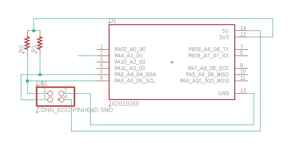
The schematic for the master circuit: (you can go back to electronics design week)
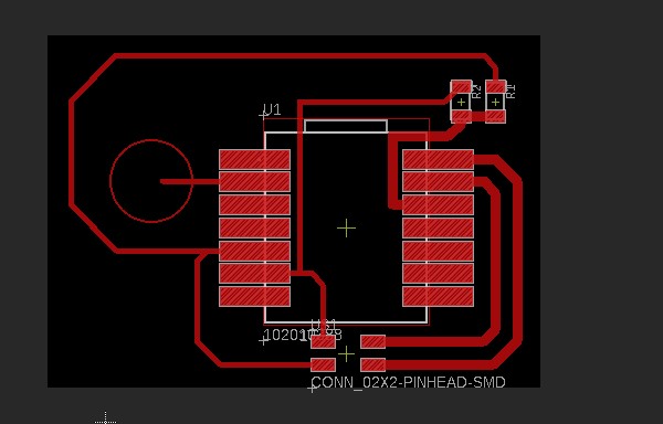
The board for the master circuit:
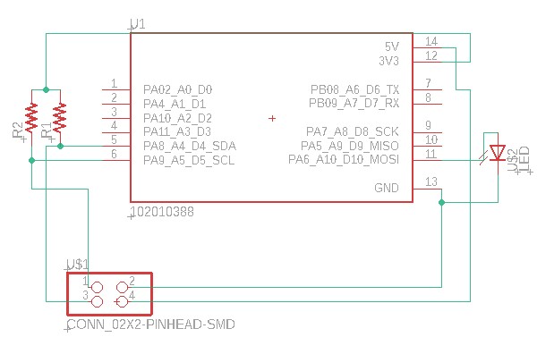
The schematic for the slave circuit:
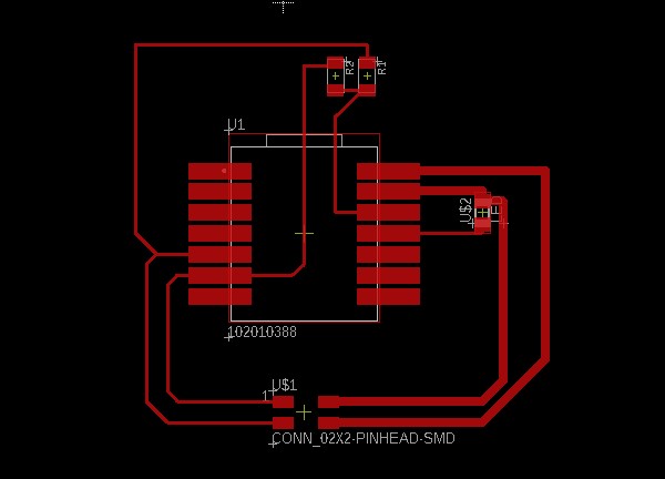
The board for the slave circuit:
PCBs after milling: (you can go back to electronics production week)

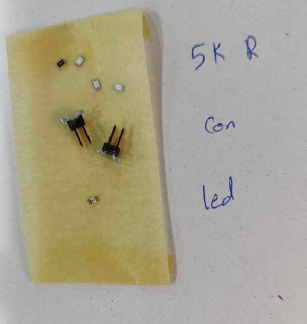
The components I used:
The master code that did not work:
int tou_pin = A1;
int tou_value = 0;

int threshold = 850;

#include <Wire.h>

void setup()
{
  Wire.begin(); // join i2c bus (address optional for master)
  pinMode(tou_pin, INPUT_PULLUP);
  Serial.begin(9600);
}

void loop()
{

tou_value = analogRead(tou_pin);
Serial.println(analogRead(tou_pin));


if(tou_value > threshold){

  Wire.beginTransmission(5); // transmit to device #5       // sends five bytes
  Wire.write(1);
  delay (100);

  Wire.endTransmission();    // stop transmitting


}}
The slave code that did not work:
int red_pin = 10;

int x = 1; //variable to save the information from the master

#include <Wire.h>

void setup() {

 Wire.begin(5);                // join i2c bus with address #5
 Wire.onReceive(receiveEvent); // register event
  Serial.begin(9600);           // start serial for output

  pinMode(red_pin, OUTPUT);


}

void loop()
{
   delay(100);
  if (x == 1){

 // Serial.println("RED LIGHT ON");
digitalWrite(red_pin, HIGH);

             Serial.println("RED LIGHT ON");


  } else {
    digitalWrite(red_pin, LOW);

  }
}


void receiveEvent(int howMany)
{
  x = Wire.read();    // receive byte as an integer
  Serial.println(x);}         // print the integer
After burning the three microcontrollers, I am now left with one Seeed SAMD21. However, I require two microcontrollers for my project. Currently, I have one Seeed SAMD21 and one Seeed RP2090. Interestingly, when I attempted to use the RP2090 as the slave, it didn’t work as expected. Therefore, I had to designate it as the master instead. However, since the RP2090 lacks a touch sensor, I will need to modify my approach. I plan to control the master microcontroller using a serial monitor instead.
Master code:
// Wire Master Writer
// by Nicholas Zambetti <http://www.zambetti.com>

// Demonstrates use of the Wire library
// Writes data to an I2C/TWI slave device
// Refer to the "Wire Slave Receiver" example for use with this

// Created 29 March 2006

// This example code is in the public domain.


#include <Wire.h> //I2C


String inputString = "";      // a String to hold incoming data
bool stringComplete = false;  // whether the string is complete


void setup()
{
  Wire.begin(); // join i2c bus (address optional for master)
  Serial.begin(9600);  //open serial communication
  inputString.reserve(200);  //to save data from serial communication

}


void loop() {

  if (inputString == "A") {
      Wire.beginTransmission(5); // transmit to device #5
      Wire.write(1);              // sends one byte
      Wire.endTransmission();    // stop transmitting
      inputString = "";
      stringComplete = false;
  } else if ( inputString == "B" ){
      Wire.beginTransmission(5); // transmit to device #4
      Wire.write(0);              // sends one byte
      Wire.endTransmission();    // stop transmitting
      inputString = "";
      stringComplete = false;
  } else {
    inputString = "";
    stringComplete = false;
  }

}


void serialEvent() {
  while (Serial.available()) {
    // get the new byte:
    char inChar = (char)Serial.read();
    // add it to the inputString:
    inputString += inChar;
    // if the incoming character is a newline, set a flag so the main loop can
    // do something about it:
    if (inChar == '\n') {
      stringComplete = true;
    }
  }
}
Slave code:
// Wire Peripheral Receiver
// by Nicholas Zambetti <http://www.zambetti.com>

// Demonstrates use of the Wire library
// Receives data as an I2C/TWI Peripheral device
// Refer to the "Wire Master Writer" example for use with this

// Created 29 March 2006

// This example code is in the public domain.


#include <Wire.h>

int x = 0;

void setup()
{
  pinMode(LED_BUILTIN, OUTPUT);
  Wire.begin(5);                // join i2c bus with address #4
  Wire.onReceive(receiveEvent); // register event
}

void loop()
{

  if(x == 1){
      digitalWrite(LED_BUILTIN, HIGH); // turn the LED off (HIGH is the voltage level)
      delay (5000);
      digitalWrite(LED_BUILTIN, LOW);
      delay (5000);


  } else if ( x == 0 ){
   analogWrite(LED_BUILTIN, 0);// turn the LED on by making the voltage LOW
   delay (500);
    analogWrite(LED_BUILTIN, 64);
    delay (500);
     analogWrite(LED_BUILTIN, 128);
     delay (500);

  } else {
    x == 3;
  }
}

// function that executes whenever data is received from master
// this function is registered as an event, see setup()
void receiveEvent(int howMany) {
  x = Wire.read();    // receive byte as an integer
}
The code I have developed functions as follows: When the serial monitor is opened, sending the character “A” to the master microcontroller (RP2090) triggers the built-in LED on the slave microcontroller to blink. Similarly, sending the character “B” causes the LED to fade, although this fade effect may not be visible in the accompanying video. If any other character is sent, the microcontrollers will not respond and no action will be taken.
When the character “A” is sent from the serial monitor to the RP2090 microcontroller, the master microcontroller will use the I2C communication protocol to send a value of 1 to the slave. The slave microcontroller will then save this value in a variable (let’s call it “x”) and blink the LED accordingly. Similarly, when the character “B” is sent, the master will send a value of 0 to the slave via I2C, which will also be saved in variable “x”. As a result, the LED on the slave microcontroller will fade based on this value.
The final result:
Here you can download the designs.