3D Printing and Scanning
Hello, and welcome to 3D printing and scanning week. Let’s get started by seeing how far 3D printers can go.
Group assignment
We will begin by performing the fundamental printer tests on the Prusa i3 MK3S+ and Ultimaker S5, which both use a 0.4mm nozzle, the layer height will be .2 mm and the infill 20%.
We are going to start with the overhang test, but before that, let me give you some background on support structures.
In 3D printing, support refers to a temporary structure that is added to a model during the printing process to provide support for overhanging or bridging areas. These areas can be difficult to print without support because the molten plastic.
An overhang refers to a part of a model that extends horizontally or at an angle beyond the previous layer’s support. When printing an overhang, there is a risk of the molten plastic drooping or sagging, resulting in a flawed print.
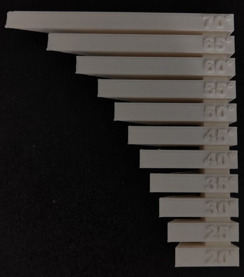
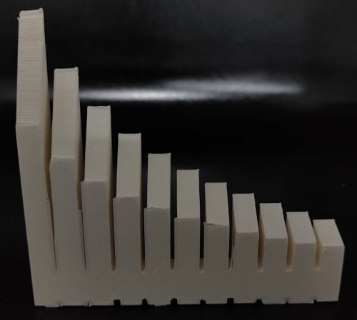
Our plan is to conduct an overhang test at angles ranging from 20 to 70 degrees to determine the point at which the print quality is impacted on both the Ultimaker and Prusa printers.
After conducting the overhang test on the Prusa printer, the results indicate that the print quality remains acceptable until we reach the 65-degree overhang angle.
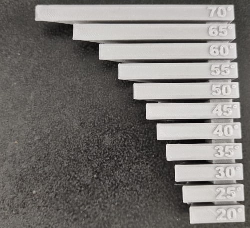
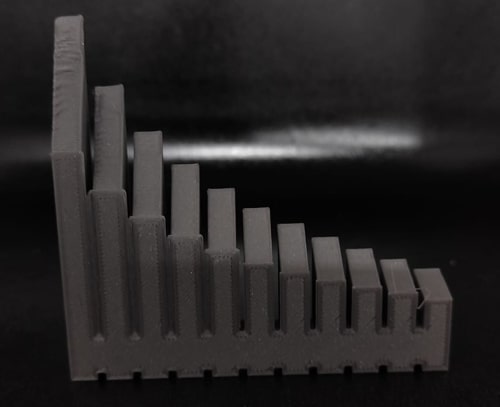
On the overhang test for the Ultimaker, the finishing remains good up to a 60-degree angle.
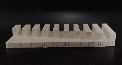
The bridge test in 3D printing is a calibration test used to evaluate a 3D printer’s ability to print bridges, which are horizontal spans of material that are unsupported from below.
The Prusa passes the bridge test even at a distance of 20 mm.
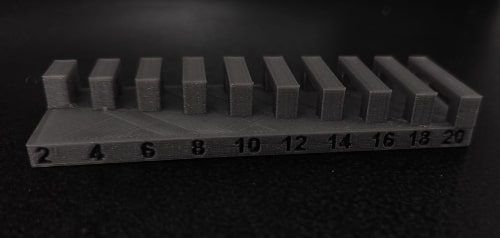
The Ultimaker print on the bridge test didn’t turn out well at 18 mm.
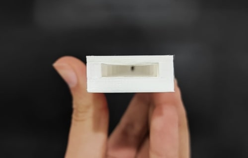
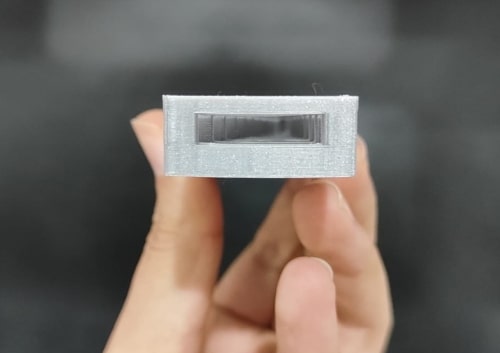
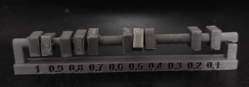
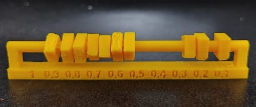
Okay, the final test is for tolerance. There is a square with a hole around the cylinder, and I have intentionally created a difference between the square and the cylinder to test the tolerance.
So, for both printers, the 0.1 mm and 0.2 mm ones, the square initially stuck to the cylinder, but then it was able to move afterwards.
I want to mention two things. The first one is that I assembled the Prusa printer that I tested:D
The second one is that the Ultimaker is two years old. On the other hand this was the first time the Prusa printer had been used.
Here you can find all test files.
Design
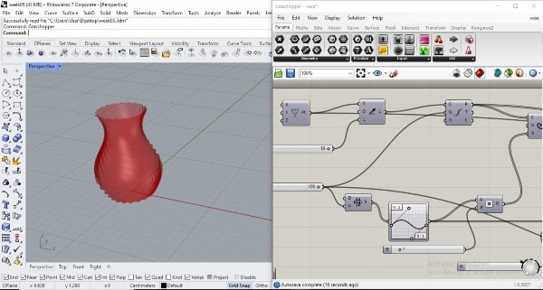
Now for my assignment, I will work on something that cannot be achieved using subtraction methods because additive manufacturing allows for more flexibility and precision in creating complex shapes and geometries It can also be more environmentally friendly, as it generates less waste than subtractive manufacturing. Therefore, I will begin designing on Rhino and Grasshopper and because this is the first time using Grasshopper, I will follow a tutorial.
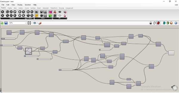
I managed to create a code for a vase that generates an infinite number of variations. I will create an infinite number of vases by changing variables instead of setting the width, length, number of edges, or smoothness to constant values. Instead, I will set them as ranges, so that with a single press I can change the design. The code will generate variable ranges for all parameters and then use them to construct walls and surfaces. By avoiding fixed numerical values, changes to parameters such as length or width will be automatically reflected in the final design, ensuring its adaptability and flexibility. I uploaded the files in the link below and I would love it if you downloaded them and tried to generate your own designs.
The first block in the code was a point, which we then connected to a vector block. Next, we fed the resulting vector into a divider block to create a set of points. Each point was used to generate a curve around it, which took its values from a domain embedded in the program. After generating the set of points and curves, I then shifted the points lists and connected them to create a mesh.
Here you can download Grasshopper code.
Here you can download my vases that I’ll fabricate.
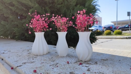
I generated three of them using the code. Now, let’s familiarize ourselves with Cura and get started on the printing process.
Cura
Cura is a free and open-source 3D printing software application that is used to prepare 3D models for printing. It allows users to import 3D models in a variety of formats, slice the model into printable layers, and adjust print settings such as print speed, layer height, and support structures. Cura is compatible with a wide range of 3D printers and can generate G-code, which is the language that controls 3D printers.
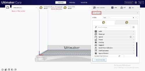
Firstly, this is the interface of Cura. I can change the printer name from here, and it will change the simulation shape of the printer to the one I choose so I can know the dimensions of the printer. Additionally, I can also change the nozzle diameter, when the nozzle diameter is smaller, it means that more details can be achieved. And I can change the material type. If I want to print something using PLA, for example, I must slice it using this material, as every material has a specific temperature requirement for the nozzle and bed plate. On the right side, there are the settings.
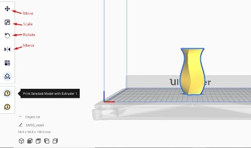
Once you import the model, the tools on the left will become active, allowing you to control the model’s location, scale, and other settings. On the left, below the tools, you will find the dimensions of the model displayed.
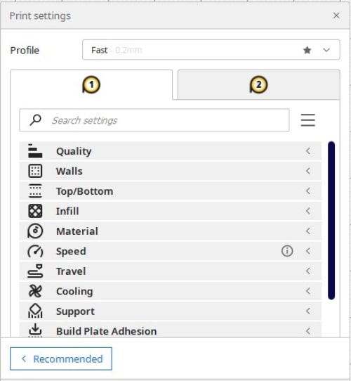
Quality
Layer height refers to the thickness of each layer of material that is deposited during the printing process. A lower layer height produces finer details and a smoother surface finish, but it takes longer to print because more layers are needed to build up the object.
Walls, Top and Bottom
Walls are the vertical surfaces of the object. They are typically thicker than the interior infill and provide the object with its overall shape and structure.
Bottom refer to the flat horizontal surface of the object that rests on the build plate.
Top is a term used in 3D printing to refer to the uppermost surface of an object.
I can decide the thickness and number of walls and layers for bottom and top.
Infill
The term “infill” in 3D printing refers to the inner structure of an object, which is made up of a pattern of material that fills the empty space between the object’s outer layers. By adjusting the infill settings in 3D printing software, it is possible to control the density and strength of the final object. A higher infill percentage indicates that more material is used to fill the space, which can result in a stronger object, but it also increases printing time and material usage.
Build plate adhesion
Is a term used in 3D printing to refer to the process of ensuring that the object being printed adheres properly to the build plate during the printing process. This is important for preventing the object from warping or coming loose during printing, which can lead to a failed print.
There are various techniques and methods used to improve build plate adhesion, such as adjusting the bed leveling, increasing the bed temperature, using brim or raft.
A brim is a thin layer of material that is printed around the base of the object. The brim increases the surface area of the object that is in contact with the build plate, improving adhesion and preventing warping.
A raft is a multi-layered foundation that is printed under the object. The raft provides a larger surface area for the object to adhere to and helps to prevent warping. The raft is printed first, followed by the object on top.
A skirt is a single layer of material that is printed around the object, but not connected to it. The skirt provides a border around the object and helps to prime the extruder, but does not provide additional adhesion.
After adjusting all the necessary settings that are appropriate for your 3D model and will help achieve the desired function, you can click on “Slice” in the lower right-hand corner of the prepare mode screen. This will start the process of generating the G-code instructions that the printer will use to create the object layer by layer.

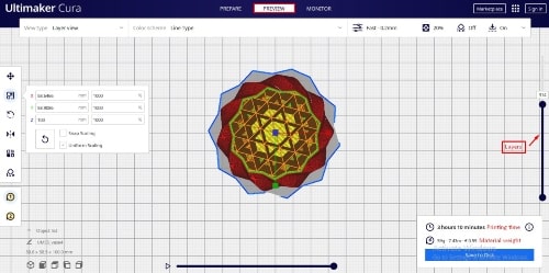
Before sending the G-code instructions to the 3D printer, it is recommended to preview the model in the software to visualize the printed model layer by layer and to inspect the infill pattern. This allows you to identify and correct any potential issues before the object is printed.
On the right side of the preview screen, there is a scroll bar that allows you to navigate through all the layers of the object. In addition to displaying the object layer by layer, the software also calculates the estimated print time and amount of material that will be used to print the object. This information is useful for planning and optimizing the printing process, as well as estimating the cost of printing the object.
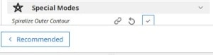
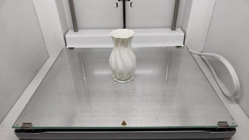
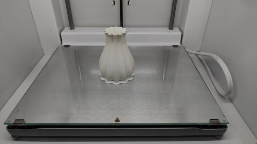
I choose to print my vases with no infill and only the outer perimeter. This technique is commonly known as vase mode or special mode.
Printing in vase mode can reduce print time and material usage since there is no need to fill the inside of the vase with material. However, keep in mind that the strength of the vase may be compromised as there is only a single wall thickness.
Overall, printing in vase mode can be a great option for creating decorative items, but it may not be suitable for functional objects that require more durability.
Ultimaker S5
Loading material
Now that we have finished slicing and the G-code is ready, we need to learn how to operate the printer.
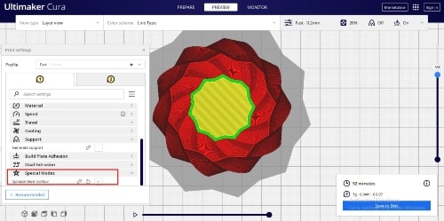
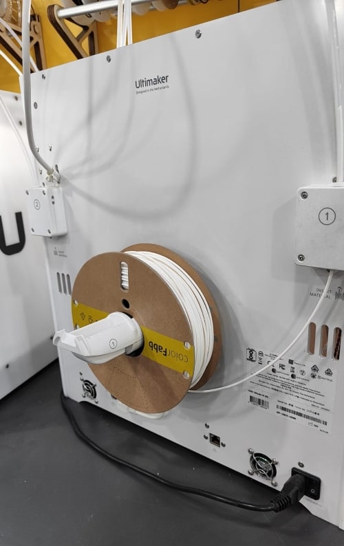
To learn how to load the material, let’s start with the steps one by one.

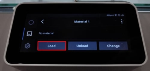

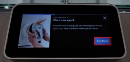
Select the material you want to use. In my case, I will use PLA.
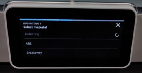
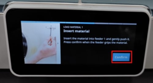
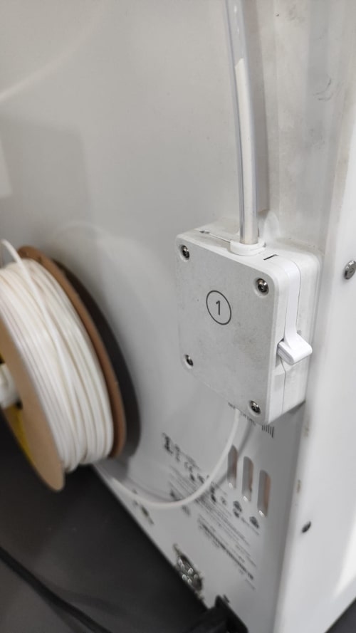
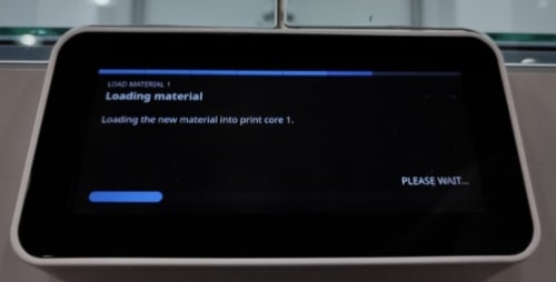
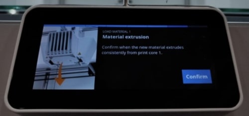
If you follow these steps, you will be able to load the material and prepare to place the model on the printer.
Print the models
Finally, I am ready to print!
There are two ways to print: the first one is over the network, and the second one is using USB. I will use the second option.
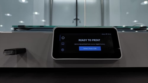
After selecting the file from a USB drive, the 3D printer will typically read the file and then start printing layer by layer.
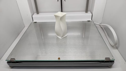
Final result
3D Scanning
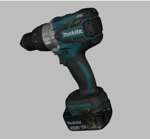
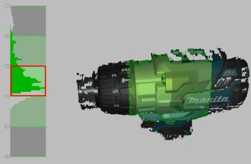
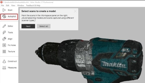
This is my first time scanning a whole model by myself, and the result is amazing. I started by scanning the drill, so let’s go and see the steps and the final result.
The name of the scanner I used is Artec Space Spider and the software is Artec Studio 17.
Okay, now let’s do the scan step by step.
Press “Scan”, then “Preview” and move the scanner until the model is clear on the screen.
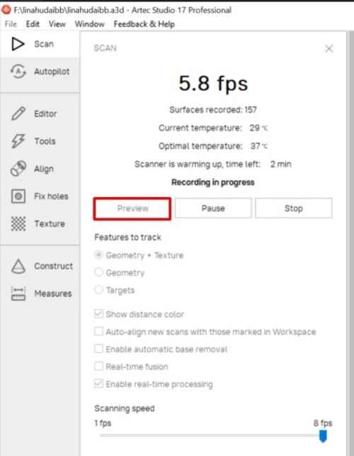
Now, you can press the push button on the scanner to start. When you finish the scan, you can press “Stop”.
Make sure there is a clear marker to set as a reference point. This will make it easier for the program to align during the alignment process.
Then, you can review the scan to identify any missing parts, and redo the scan in those areas.
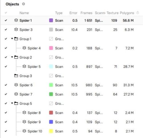
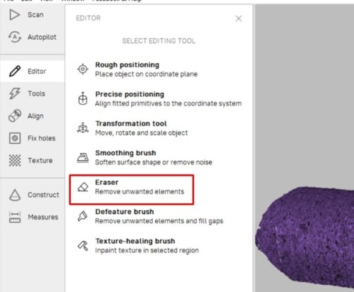
After scanning, you can go to the editor and erase any unwanted parts.
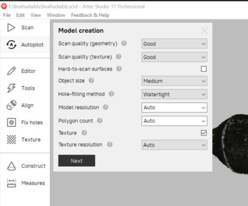
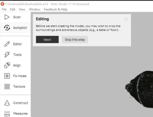
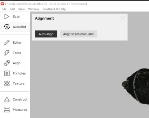
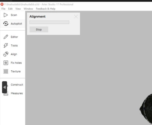
When you are almost satisfied with the results, press “Autopilot” and follow the steps.
We can skip this step if we already cleaned up the scans.
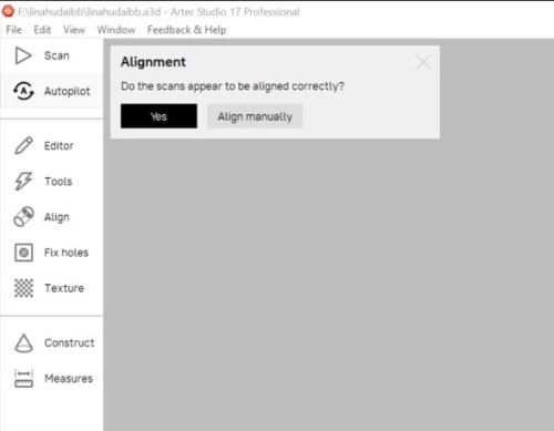
If the scans are aligned properly, and you are satisfied with the result, let’s generate the fusion file.
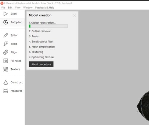
Finally, here we are!