Week 6: Electronic Design
what to do ??
-
Group project:
- use the test equipment in your lab to observe the operation of a microcontroller circuit board
-
Individual project:
- design a development board to interact and communicate with an embedded microcontroller
- extra credit: try another design workflow
- extra credit: make a case for it
- extra credit: simulate its operation
Group Assignment
for this week we use our test lab instrument to observe the operation of a microcontroller circuit board ,our circuit contain a esp32 microcontroller , red led and potentiometer ,we use the oscilloscope to observe the voltage wave behavior on the led when we change the potentiometer value
Also we learn about how to use these devices :
- The Multimeter
- Regulated Power Supply machine
- Oscilloscope
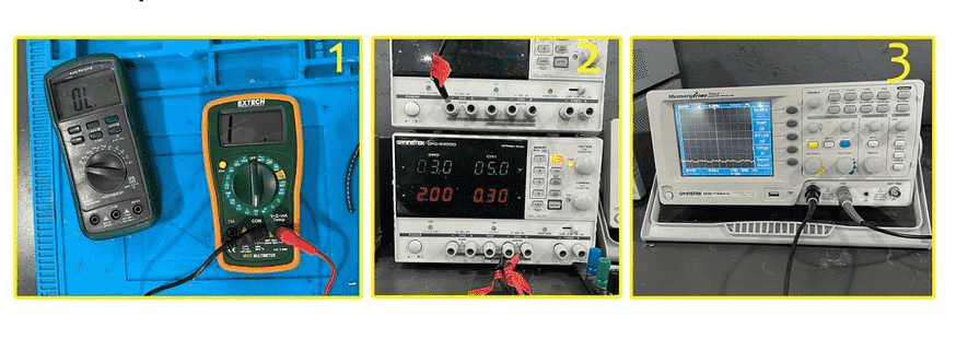
The image used in previous section were sourced from the following resource: My colleagues Rasha documentation
Multimeter
A multimeter is composed by four essential sections:
- Display: this is where the measurements are displayed
- Selection knob: this selects what you want to measure
- Ports: this is where you plug in the probes
- Probes: a multimeter comes with two probes. Generally one is red and the other is black
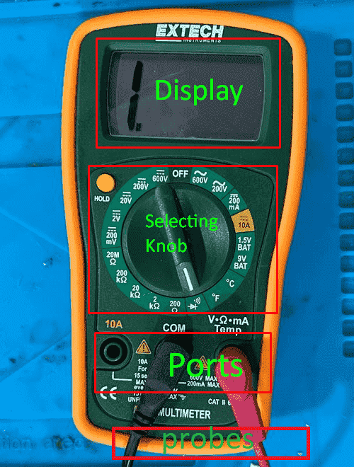
The image used in previous section were sourced from the following resource: My colleagues Mohammed documentation
you can by multimeter measure voltage ,current ,resistance and continuity
Measuring dc and ac Voltage :The V with a straight line means DC voltage,The V with the wavy line means AC voltage.
To measure voltage:you will follow those steps
- Set the mode to V with a wavy line if you are measuring AC voltage or to the V with a straight line if you are measuring DC voltage.
- Make sure the red probe is connected to the port with a V next to it.
- Connect the red probe to the positive side of your component, which is where the current is coming from.
- Connect the COM probe to the other side of your component.
- Read the value on the display.
If you need to measure the voltage of something,you should select voltage range in which the value will fall under, if you don't know exactly the range you need to try several ranges.
If the range you have selected is lower than the real value, on the display you will read 1. The 1 means that the voltage is higher than the range you have selected.
If you select a higher range, most part of the times you will be able to read the value of the voltage, but with less accuracy.
if you want to measure the current you will just move the nob to current and put the prop in series connection with element you want to measure and of course you need to chose right range value
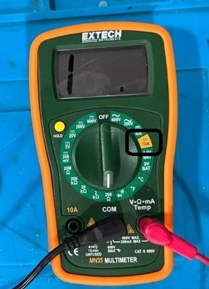
The image used in previous section were sourced from the following resource: My colleagues Mohammed documentation
and this steps you will make it with other properties that you need to measure
A very important properties that Most multimeters provide that allows you to test the continuity of your circuit,
that will help you to easily detect bugs such as faulty wires. It also helps you check if two points of the circuit are connected,
To use this functionality select the mode that look like a speaker.
WARNING: To test continuity you should turn off the system! Turn off the power supply!
How does continuity work?
If there is very low resistance between two points, which is less than a few ohms, the two points are electrically connected and you'll hear a continuous sound.
If the sound isn't continuous or if you don't hear any sound at all, it means that what you're testing has a faulty connection or isn't connected at all.
Power Supply machine
A DC power supply is an electronic device that converts AC (alternating current) power from a wall outlet into a steady DC (direct current) voltage that can be used to power electronic devices. DC power supplies are commonly used in a variety of applications, including electronic manufacturing, laboratory testing, and consumer electronics. They come in various sizes and power ratings, ranging from small portable units to large bench-top models capable of supplying high voltages and currents. DC power supplies can also be designed to have adjustable output voltages, current limiting, and other features to suit different applications.
How to use it ??
- Determine the voltage and current requirements of the device you want to power.
- Set the output voltage and current on the DC power supply to match the device's requirements.
- Connect the positive (+) and negative (-) output terminals of the DC power supply to the corresponding input terminals of the device you want to power.
- Turn on the DC power supply and verify that the voltage and current readings on the display are within the desired range.
Oscilloscope
An oscilloscope is an electronic test instrument used to display and analyze the waveform of electrical signals. It is used to measure and observe the amplitude, frequency, and other characteristics of electrical signals in both the time domain and frequency domain. Oscilloscopes are commonly used in electronics, telecommunications, engineering, and science fields.
The basic components of an oscilloscope include a display screen, vertical and horizontal controls, input connectors, and a trigger system. The vertical controls adjust the amplitude or voltage of the signal being measured, while the horizontal controls adjust the time scale of the waveform. The input connectors are used to connect the signal being measured to the oscilloscope. The trigger system is used to stabilize the waveform and ensure that it is displayed correctly on the screen.
How to use it ??
To use an oscilloscope, you need to connect the signal being measured to the input connectors of the oscilloscope, adjust the vertical and horizontal controls to display the waveform correctly on the screen, and use the trigger system to stabilize the waveform. Once the waveform is displayed, you can use various tools and features on the oscilloscope to analyze the waveform and extract information about the signal being measured.
Individual Assignment
What is PCB ?
-
Printed Circuit Board
-
Mechanically supports and electrically connects electronic
components using conductive tracks, pads and other features
etched from coper sheets laminated onto a non-conductive
substrate.
or In easy way, it is an electronic assembly that uses copper conductors to create electrical connections between components.
-
Mechanically supports and electrically connects electronic
components using conductive tracks, pads and other features
etched from coper sheets laminated onto a non-conductive
substrate.
-
Two purposes:
- A place to mount the component
- Provides the means of electrical connection between the components
-
PCBs can be
- Single sided (one copper layer)
- Double sided (two copper layers)
- Multi-layer
PCB Terminology -component mounting methods
-
Through-hole
- Soldered to the opposite side of the board
-
SMD/SMT (surface mount device/technology)
- Soldered in the same side of the board
- Can be mounted on both sides of the PCB
-
pad
- A small surface of copper where component will be soldered to the board
-
Via
- plated hole that allows the current to pass thru the board
-
Soldermask
- a layer of insulating lacquer covering both surfaces of the board to prevent the solder to short- circuit two tracks from different nets.
-
Track (trace)
- conductive path connecting 2 points (pads, vias)
-
Silkscreen (overlay)
- letters printed on the final board.
.jpeg)
.jpeg)
.jpeg)
.jpeg)
.jpeg)
useful source to learn more University of Idaho - PCB Design with EAGLE
PCB design software
so now, we know some basic terminology and information about pcb,but how I can design and draw my own pcb ,there are different softwares that can be used to design pcb board
like Eagle software , Kicad software ,for me I used Eagle software to design my board ,but almost all softwares have the same process flow and logic ,so learn one software will help you to have that logic,
So , lets now go deep with eagle
what is Eagle?
-
-
Easily Applicable Graphical Layout Editor
- Easy to use CAD tool for designing PCBs
- CadSoft
-
Easily Applicable Graphical Layout Editor
-
-
Consist of three main modules:
- Schematic editor
- Layout editor
- Autorouter
-
Consist of three main modules:
Eagle User Interface
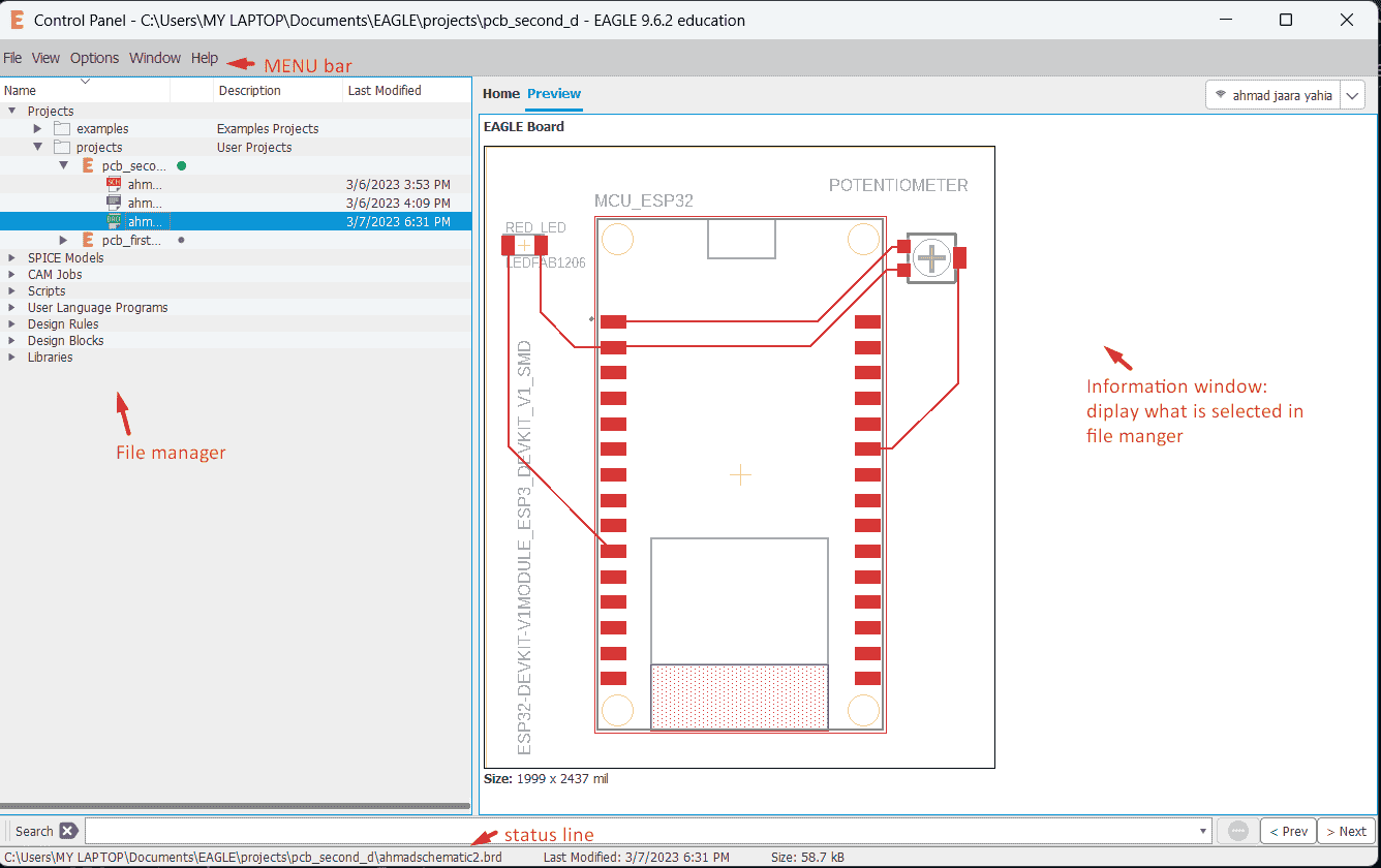
so the work flow will move generally in three steps, firstly, create a project ,then create a schematic design to add your component ,lastly convert it to a board
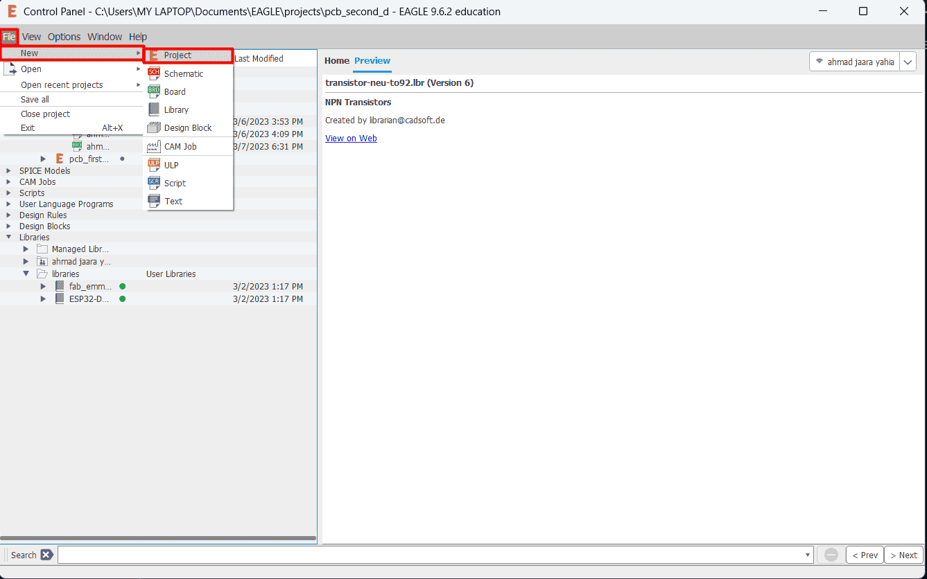
create a project as shown below
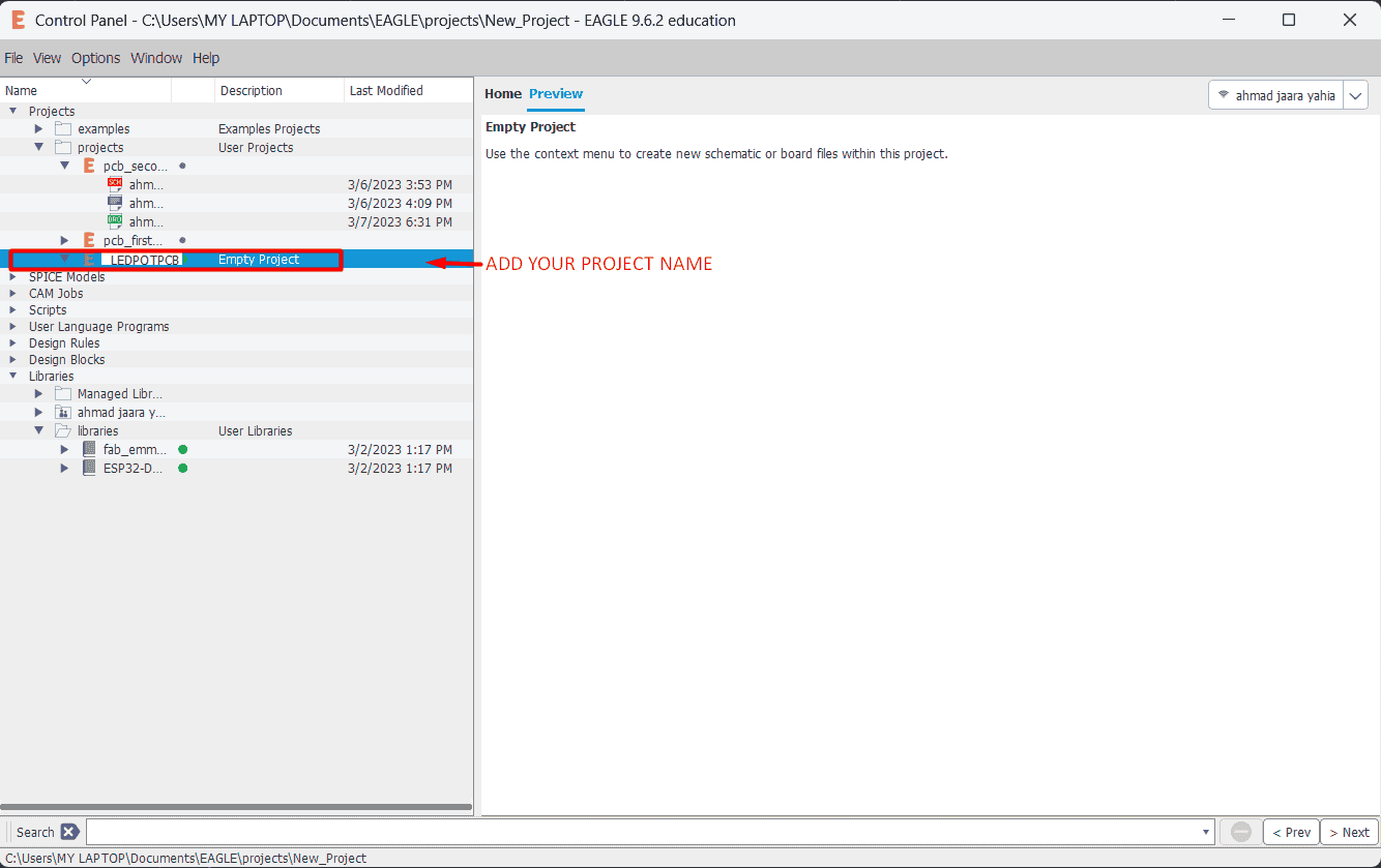
name your project as shown below
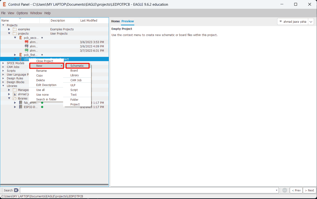
create schematic file by click right click and click new schematic then the schematic window will appear
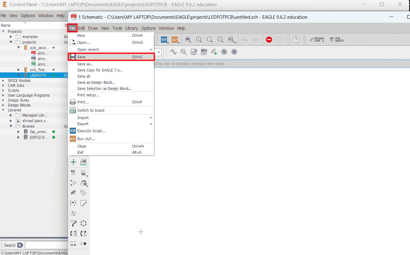
save your schematic file
adding grid to your sheet that will help you in your design
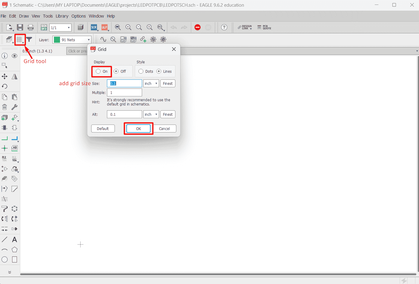
so, now I will add my part Mcu,led and potentiometer ,click add tool and then chose the part ,by clicking double click on the component you want or just select component then click on ok
so my components will be led,potentiometer and Mcu esp32 div ket
Why I chose these component ??
I chose these components for a few reasons. First, I believe that using a potentiometer to control LED lighting will be an interesting challenge for me and provide a unique way to manipulate the lighting.
From a technical standpoint, the microcontroller will serve as the 'brain' of the circuit. It will receive signals from the potentiometer, which acts as the input device. Then, the microcontroller will send signals to the LED, which acts as the output device, directing it to perform specific actions like turning on or off, or blinking, for example.
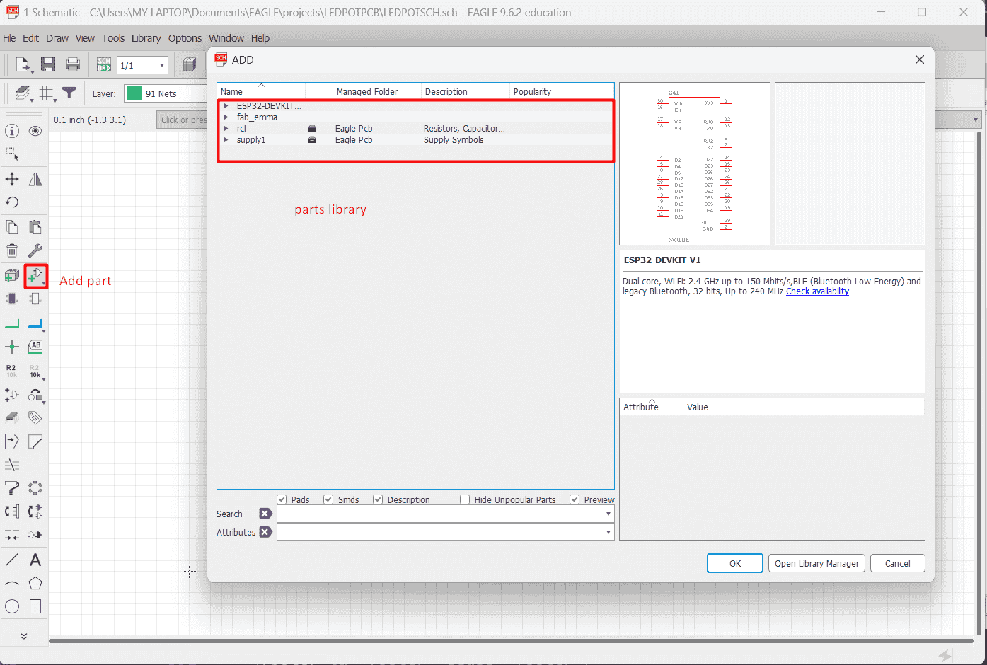
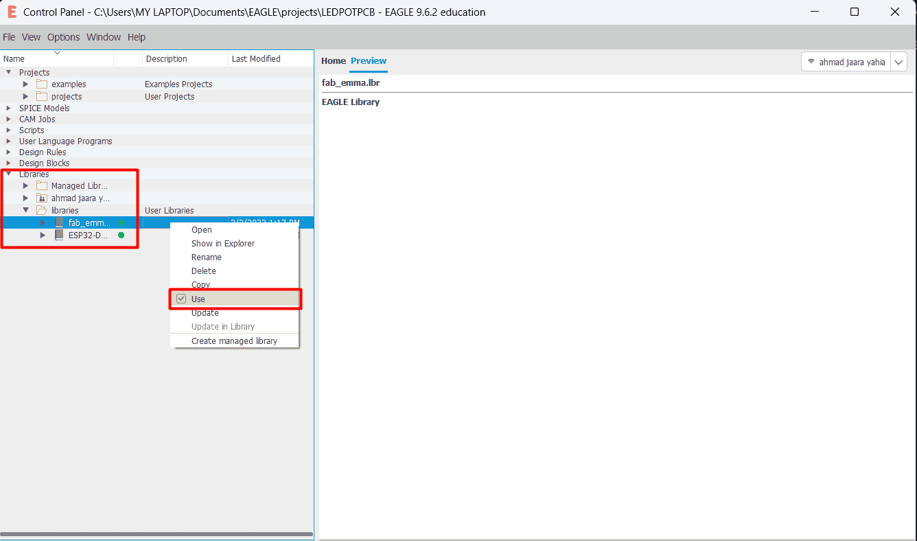
to active a library you just go to control panel and right click on the library you want and click on use
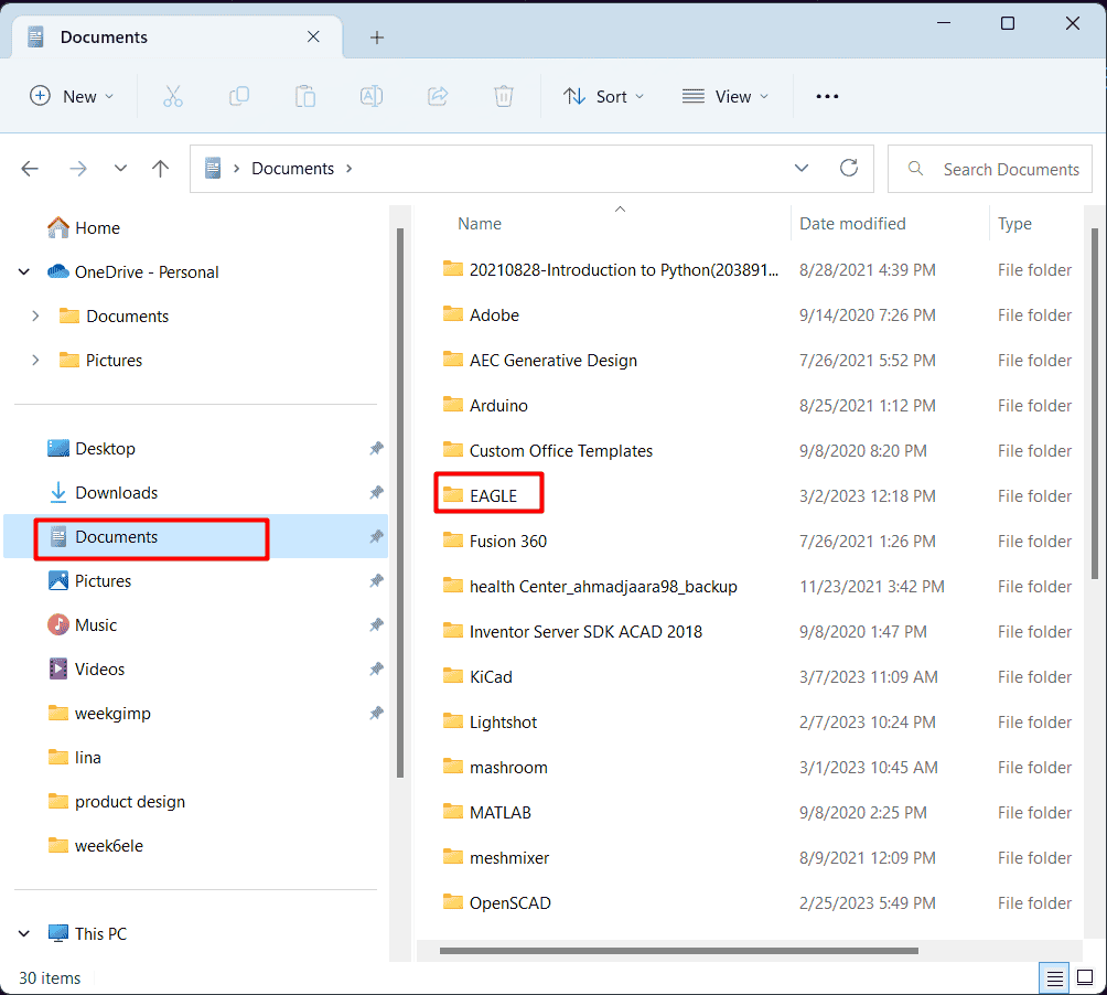
if the part you want does not exist in default library you can add your library as follow
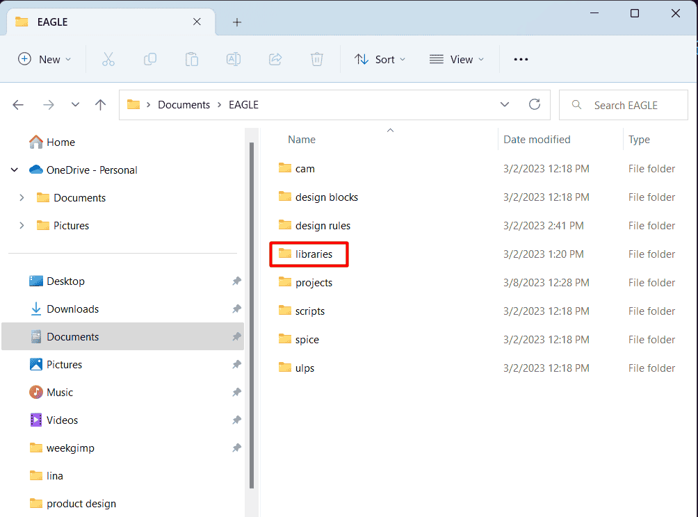
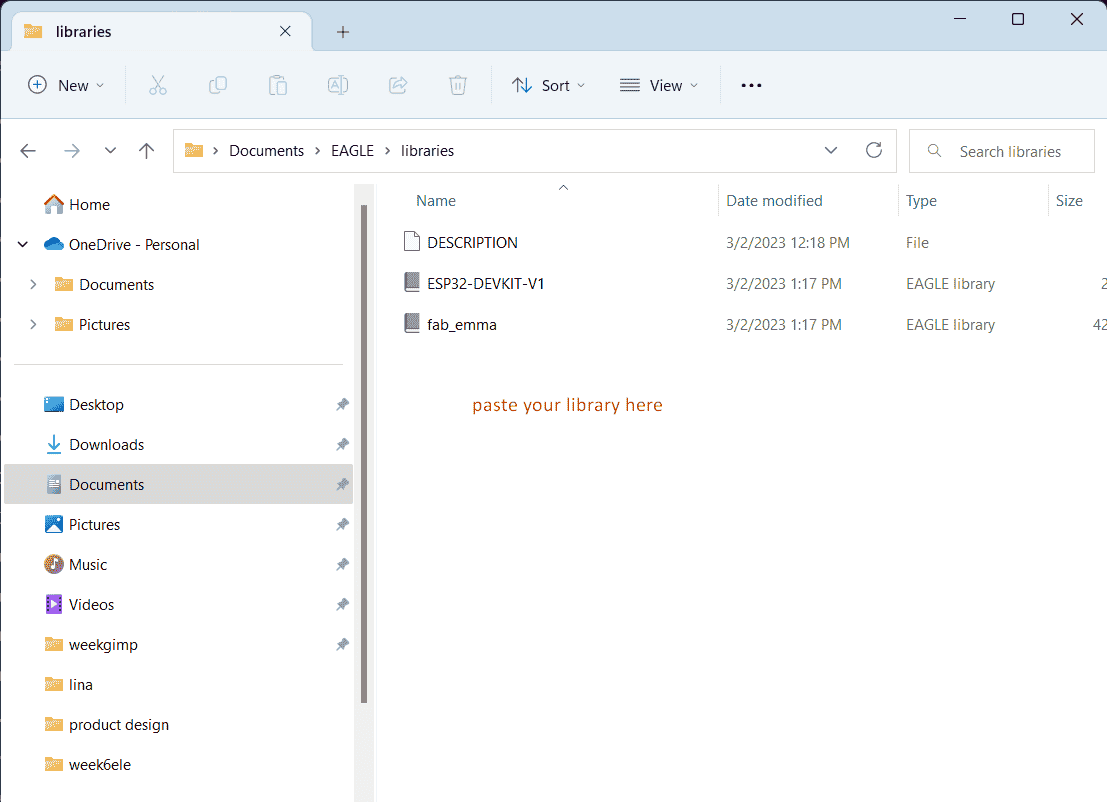
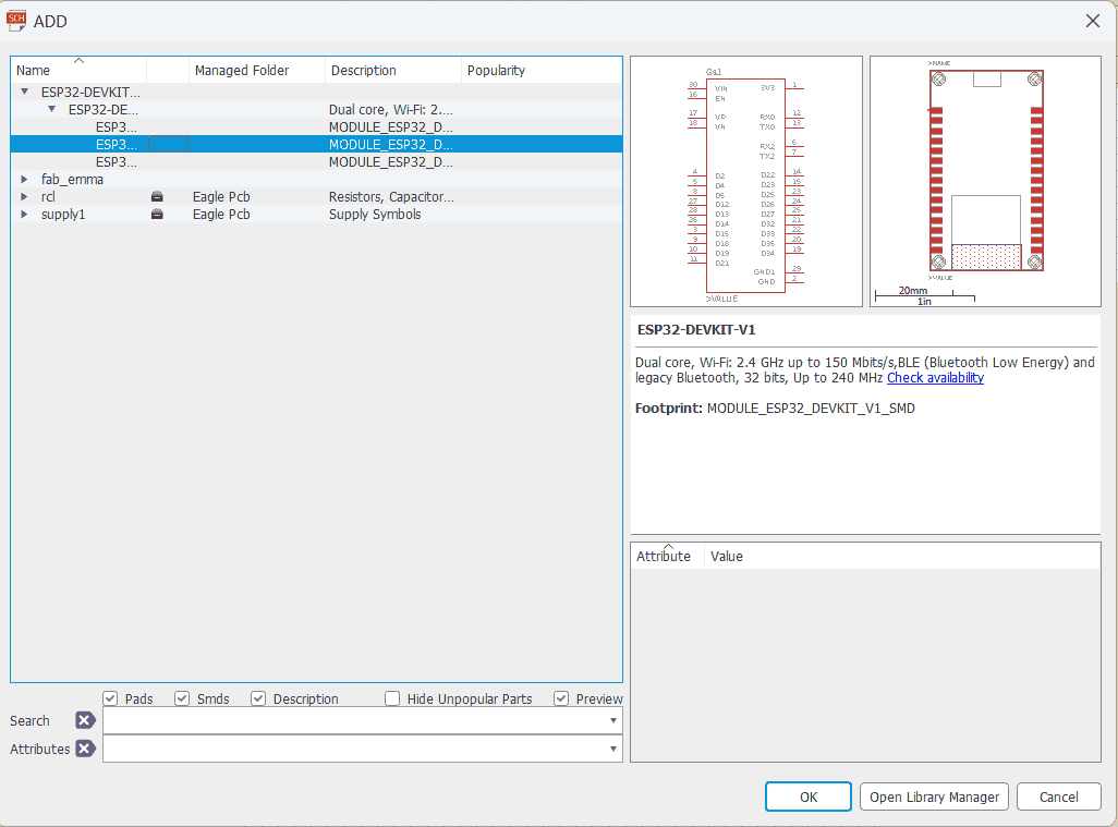
now in add window I chose the footprint for the component that I need for my pcb design click ok or double click ,click on work window to add your component ,press ESC to go back to add window and chose other component ,when you finish adding your components you just press cancel in add window to close it
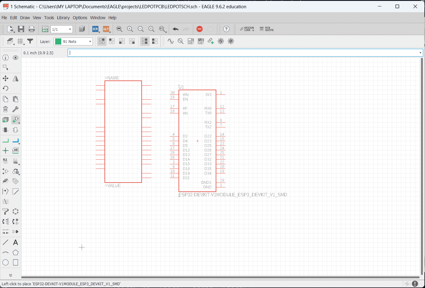
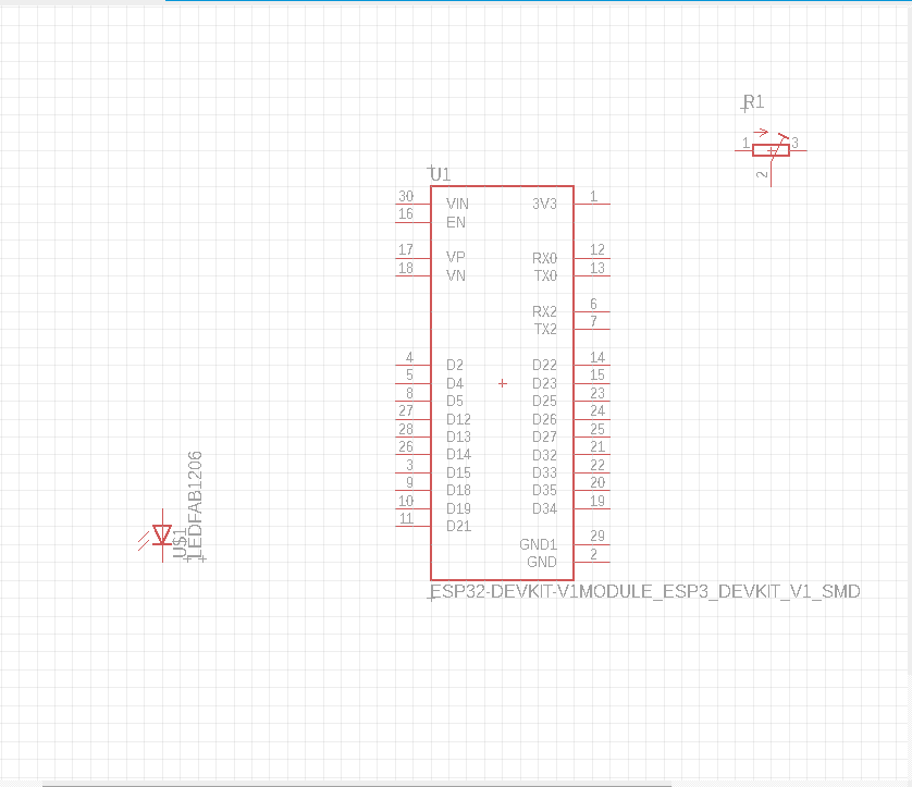
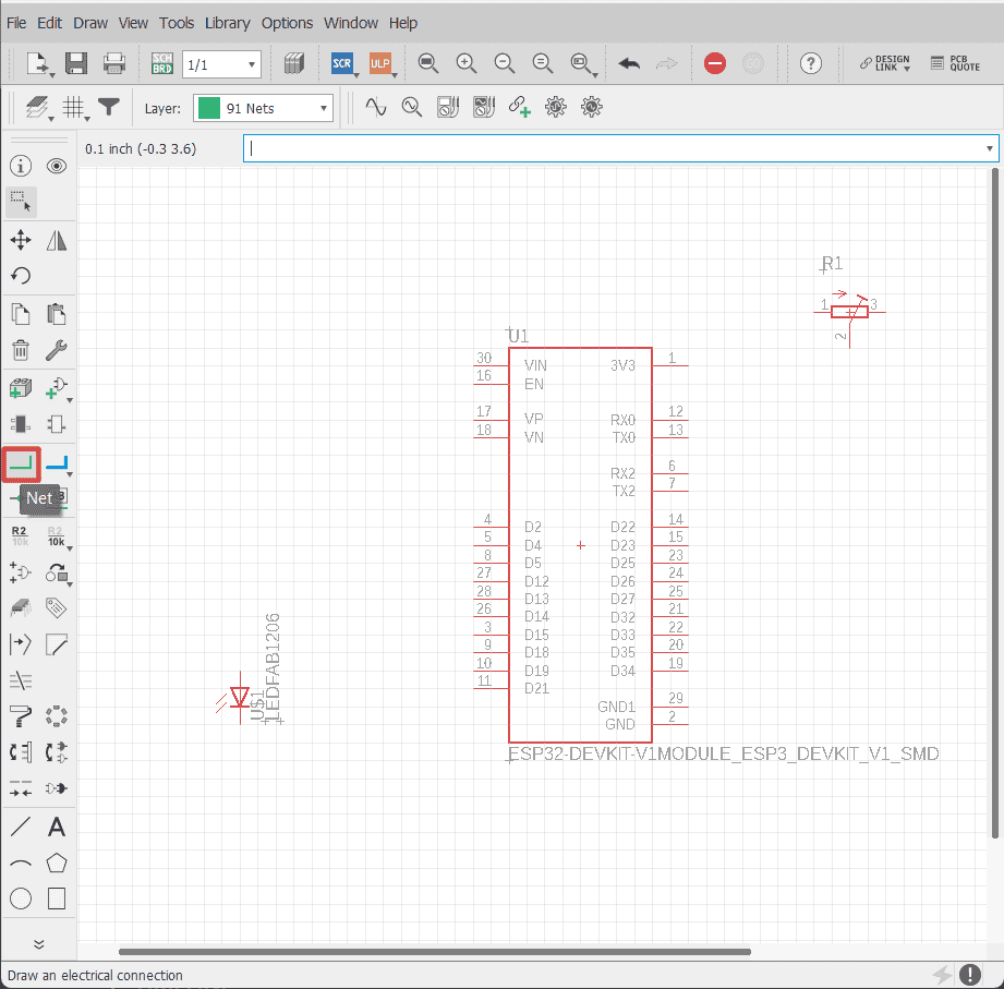
to connect the component with wire you click on net tool to start making the wire connection
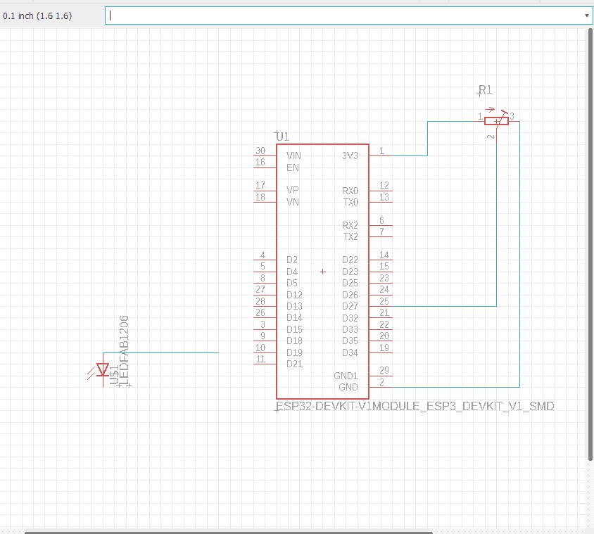
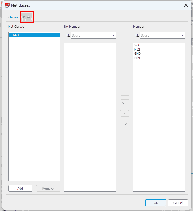
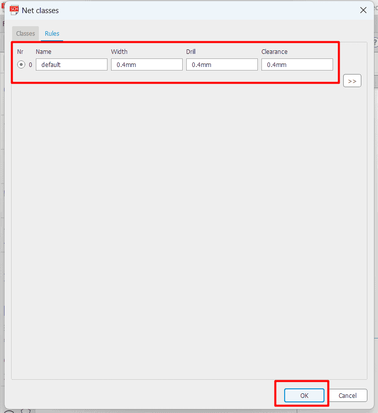
to determine the net wire thickness you can determine that by click on edit ,then click on net classes ,then you click on rule ,you add your values for width ,drill and clearance then okay
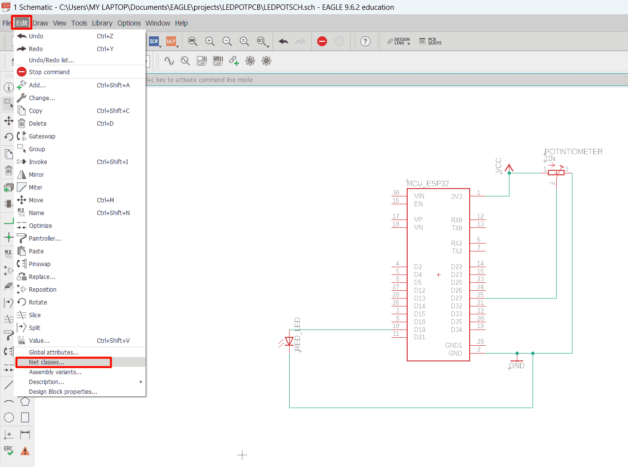
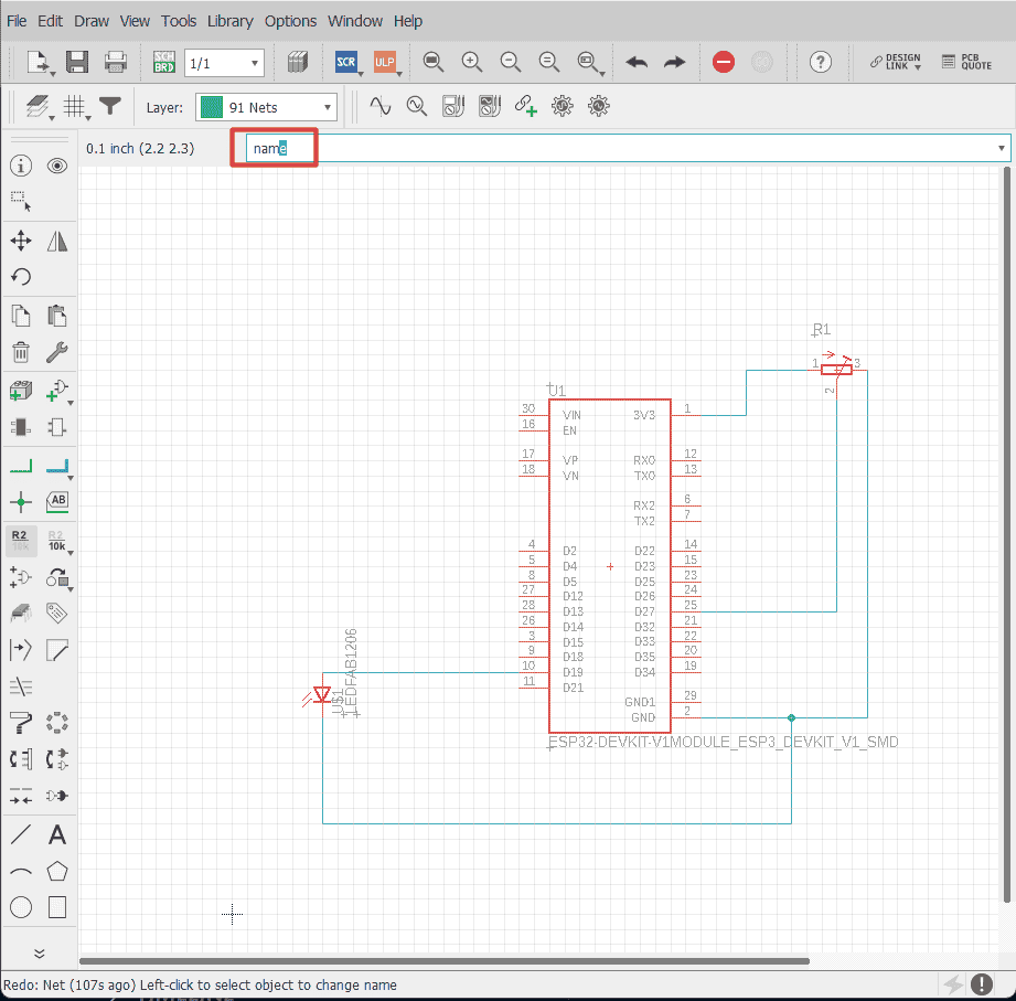
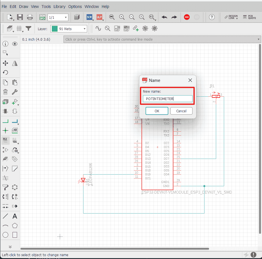
to change the components name ,you can write name in the command bar and click on the component ,a window will appear ,write the name then click ok
to delete any component you can click on delete tool or write delete on the command bar
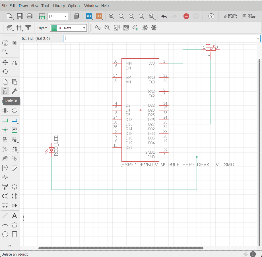
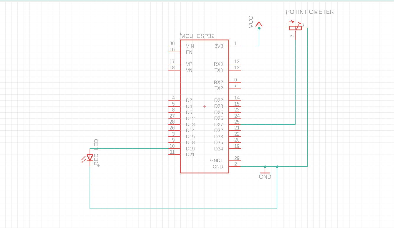
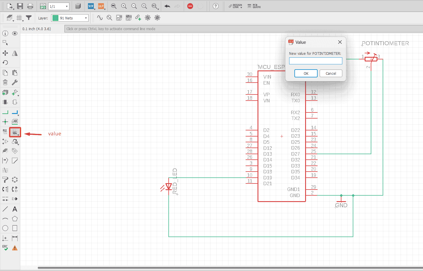
to add values to the components like the potentiometer resistance value ,you will use the value tool
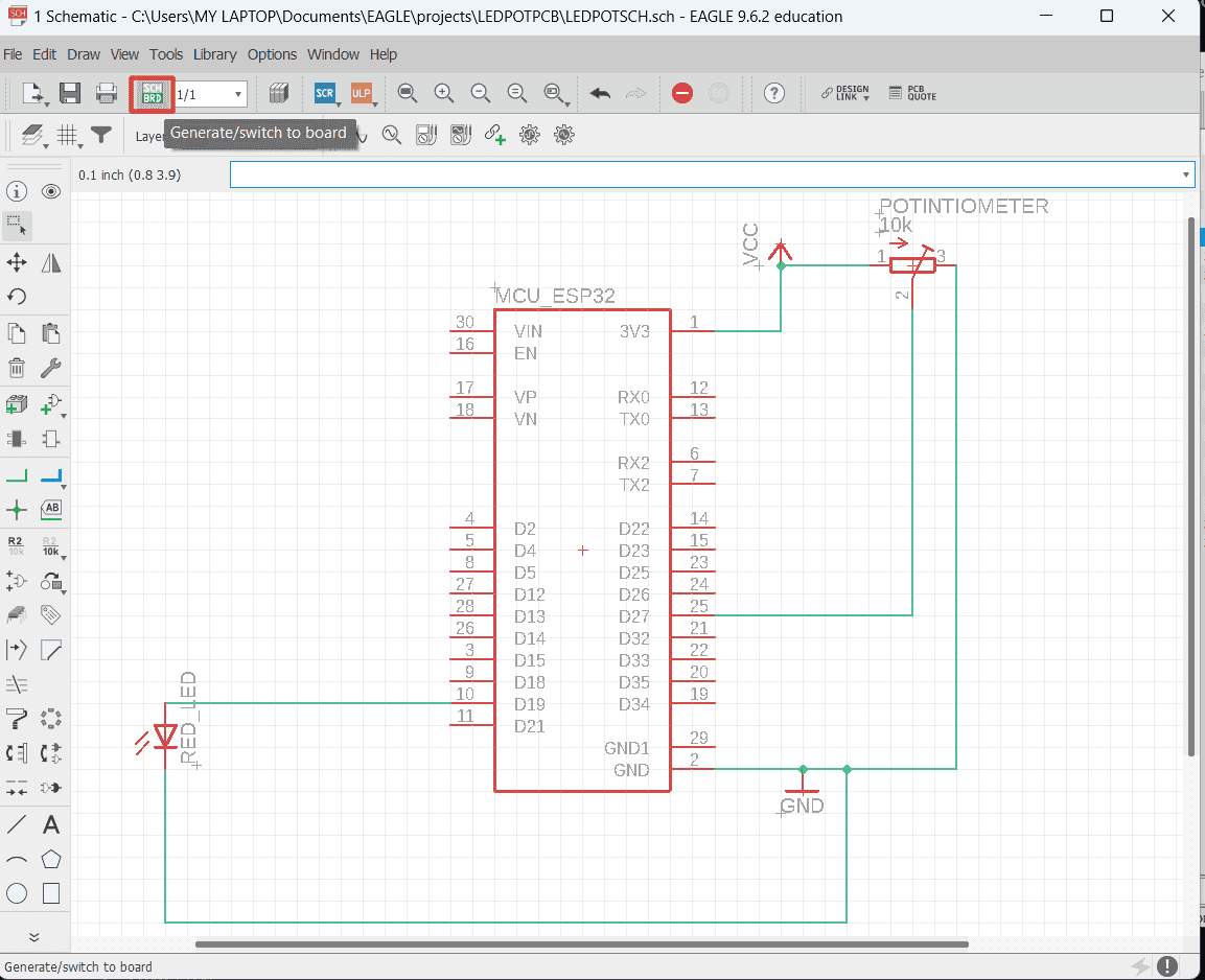
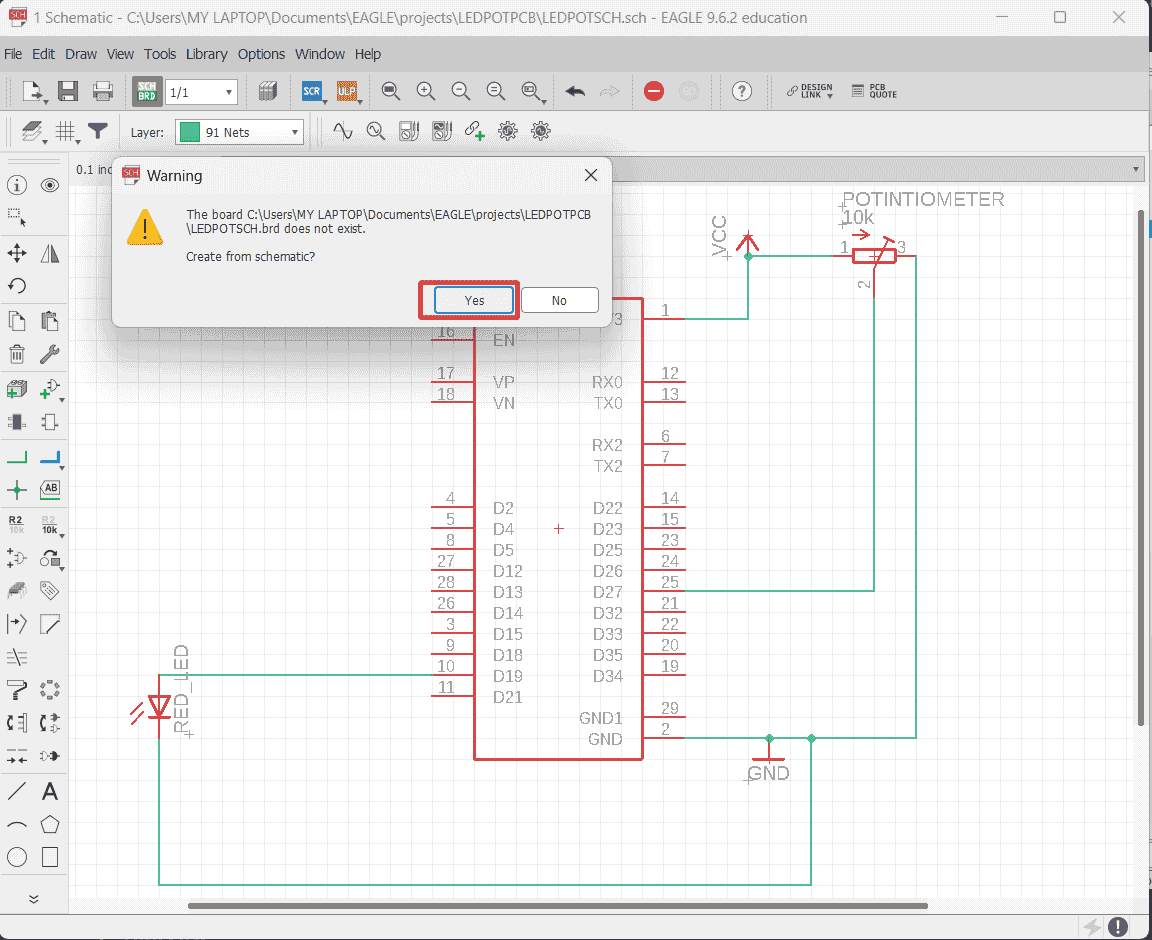
to transfer your electric design schematic to board design to prepare the design for pcb manufacturing ,click on generate board tool a pop up window will appear to announce you that you will generate a board from the schematic ,click yes
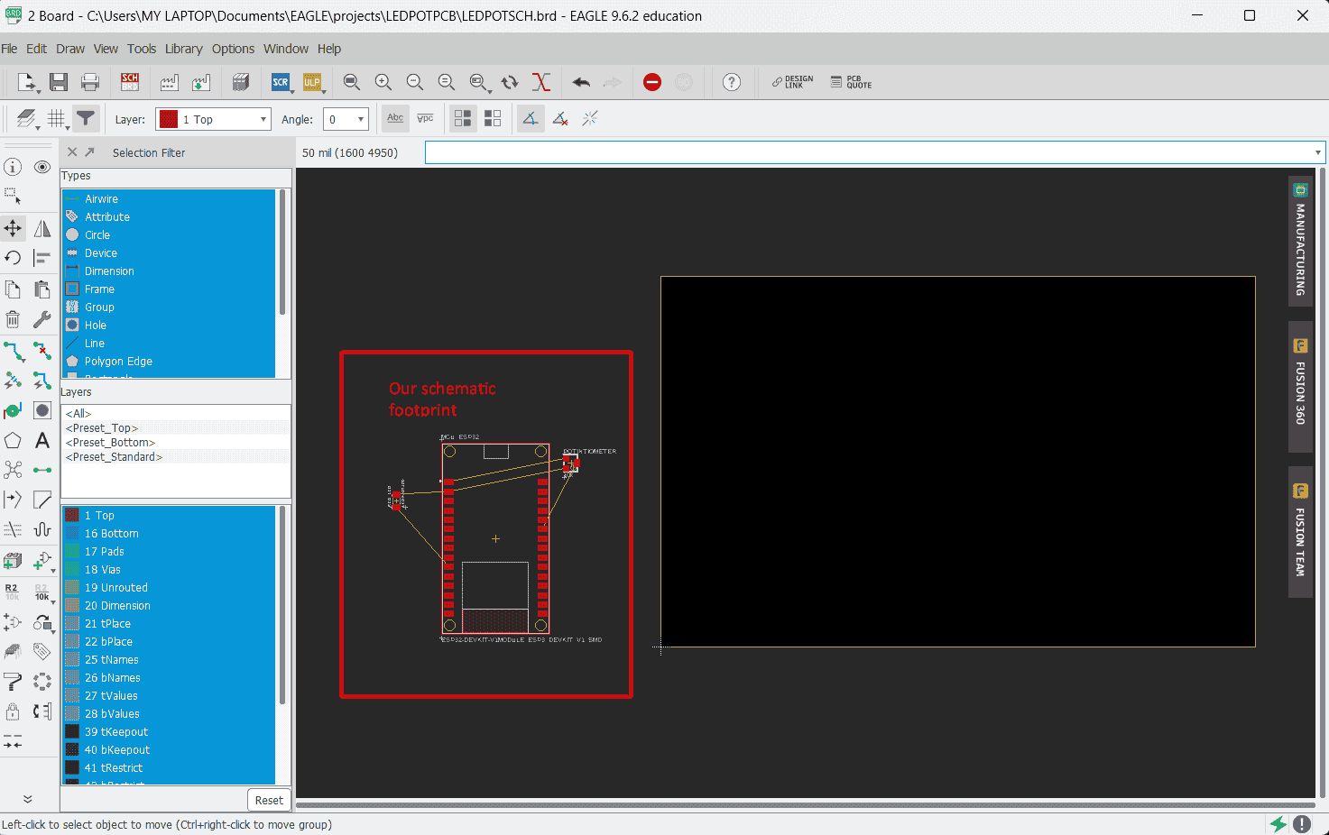
your design footprint will shown ,the black box represent the board ,you can chang its dimension easily by drag its edge to the size you want
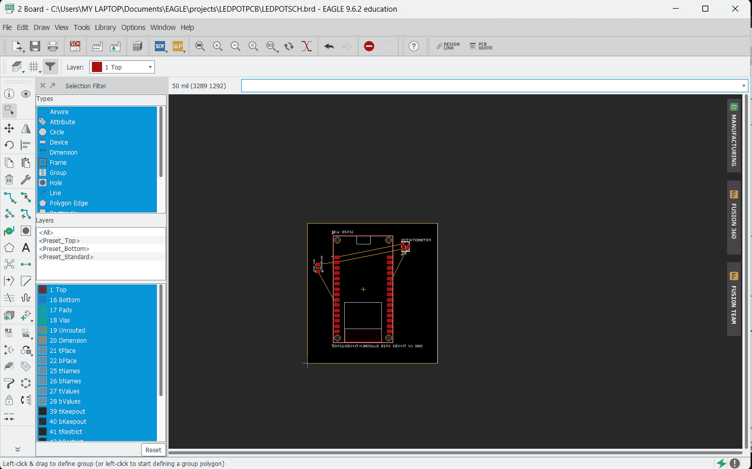
move your design inside the black box
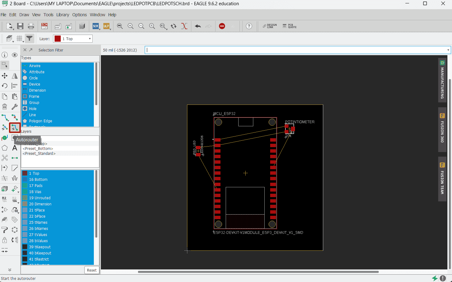
to auto route your component you click on Autorouter tool
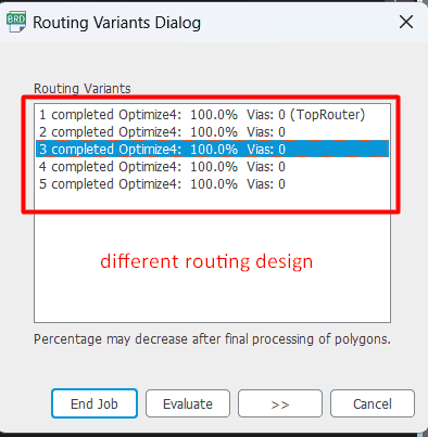
chose the effort low then click on continue ,then click start and it will make 4 suggestion design for you ,chose one of the suggestion design
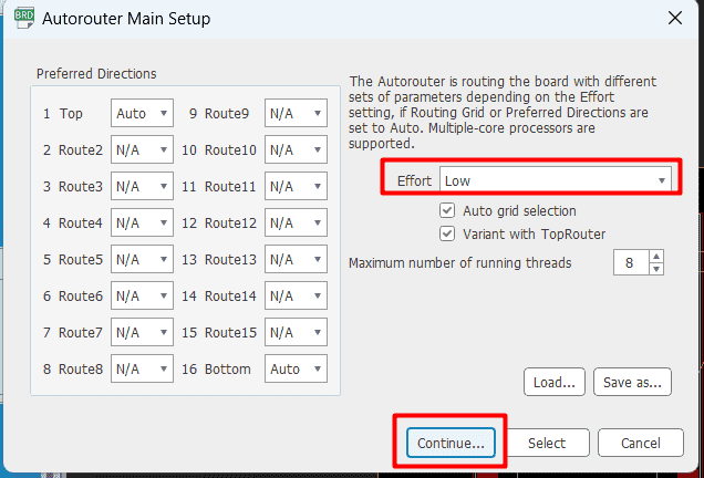
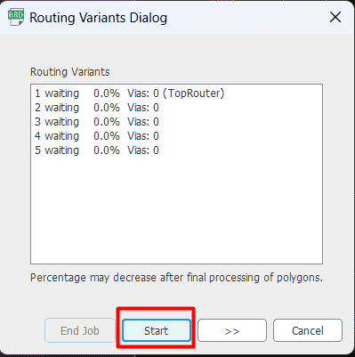
double click on the design you want and it will give you that design
to add a board design rule to check your trace are follow your requirement ,for me I will use a bit diameter equal to .4 mm so I will add this requirement to the DRC window
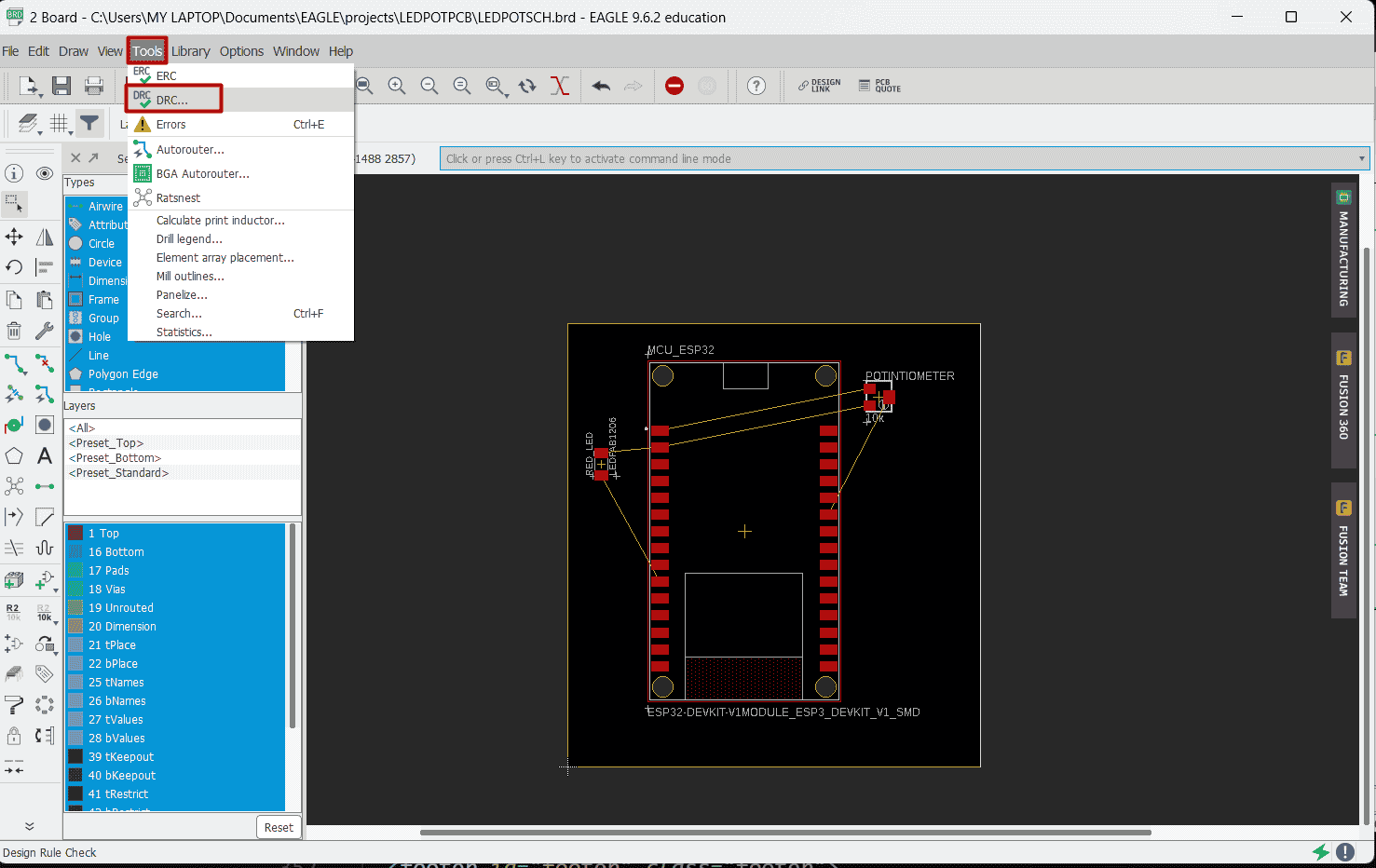
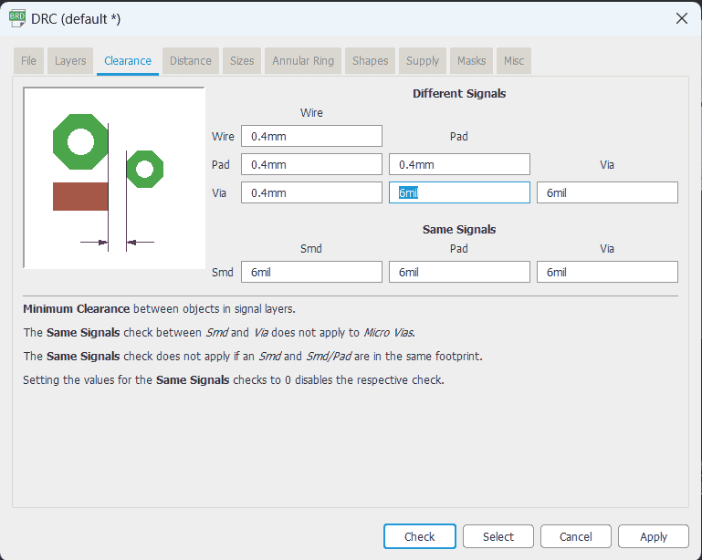
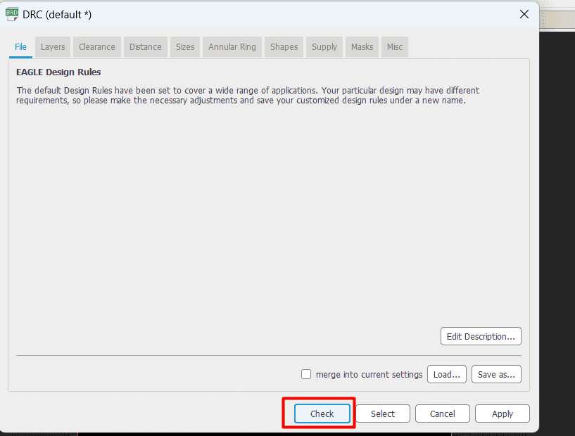
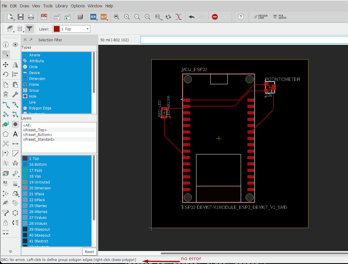
check drc rule ,look at status bar to see if there is any error
and now our board are ready
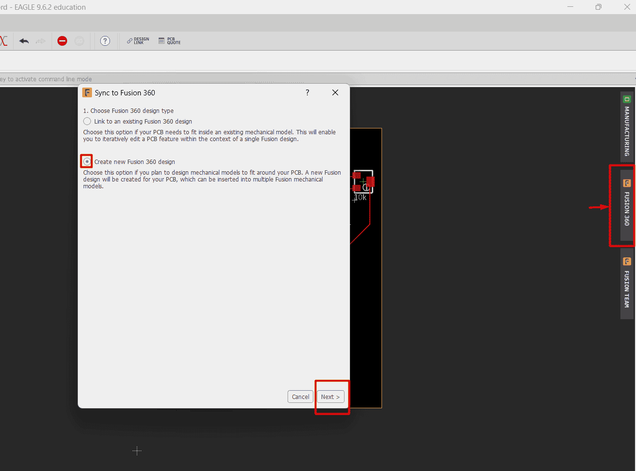
to send push your design to fusion360 click on fusion 360 button ,select create a new fusion 360 design then click next
chose the location to save design okay
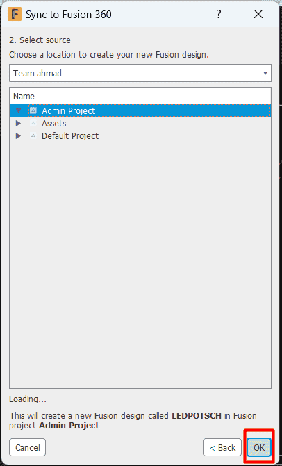
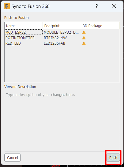
here you click on push and thats it

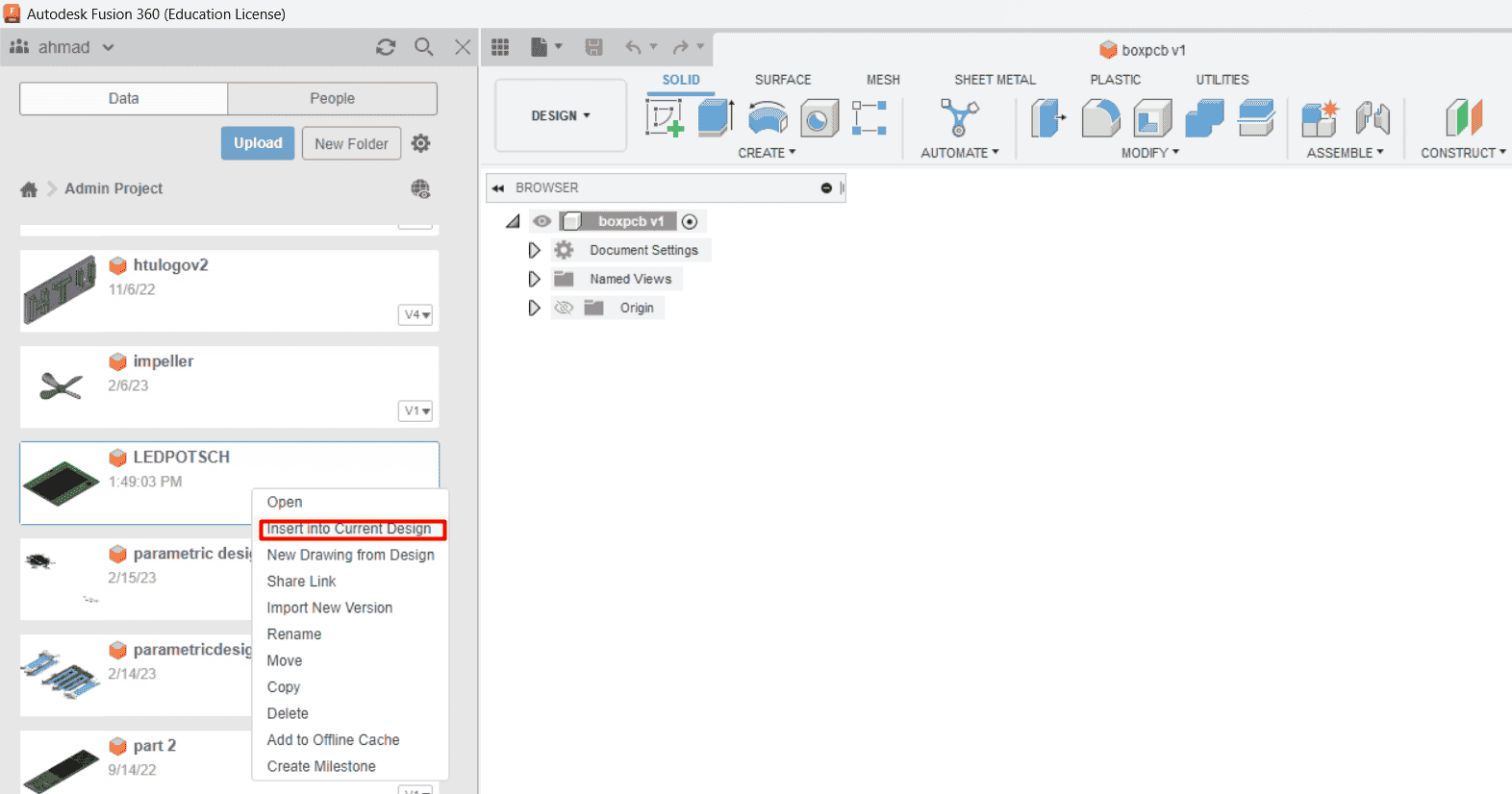
In fusion , go to the location that you save your pcb board at ,click right click and click insert into current design
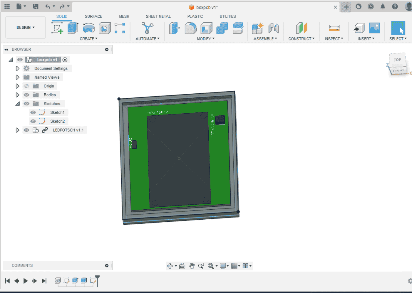
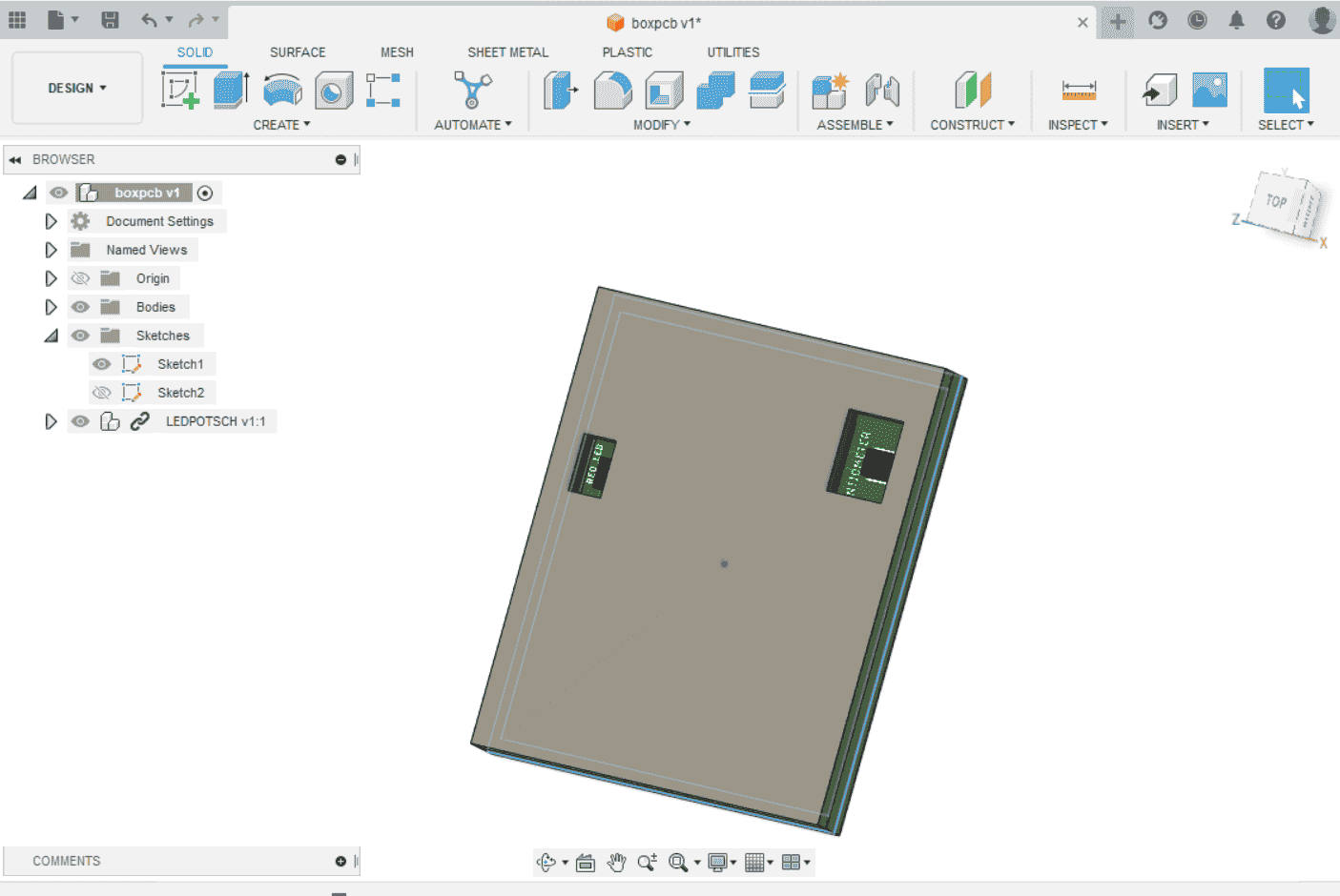
add your design , I make a box case that have to window for potentiometer and led components
.svg)

